Wastewater Treatment Plant Design Project Report - Safety
VerifiedAdded on 2022/08/11
|7
|549
|19
Project
AI Summary
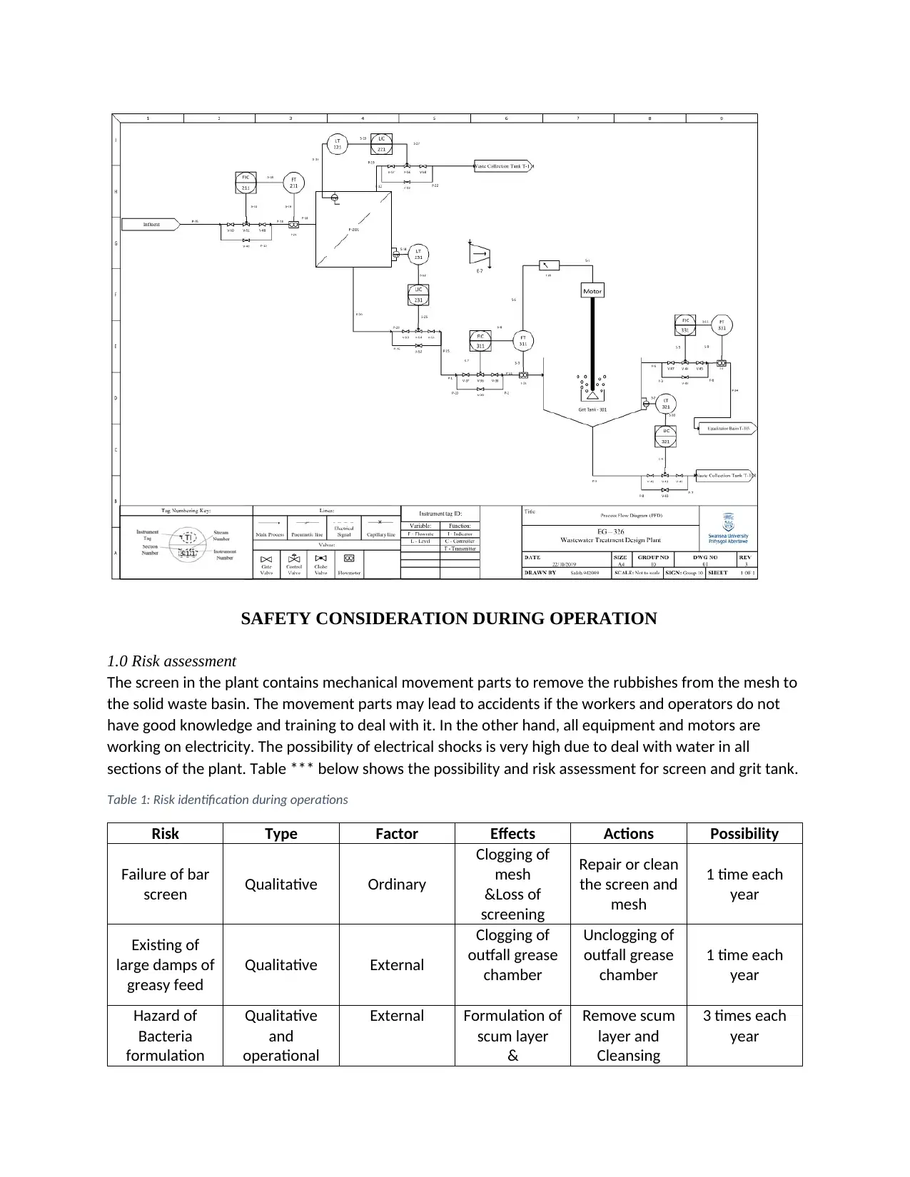
This project presents a comprehensive design of a wastewater treatment plant, focusing on the design of a bar screen, grit and grease removal tanks, and an aeration tank. The design considers a plant serving over 200,000 people in the UK. The project includes a detailed risk assessment of plant operations, identifying potential hazards associated with mechanical movements and electrical equipment. A What-If analysis is conducted to evaluate potential operational issues and recommend safeguards. Furthermore, the design of a feed air compressor is detailed, including specifications and performance calculations. The report also includes the design of influent main pump and piping and instrumenting. This project provides a practical application of environmental engineering principles to ensure efficient and safe wastewater treatment processes.
1 out of 7
Your All-in-One AI-Powered Toolkit for Academic Success.
+13062052269
info@desklib.com
Available 24*7 on WhatsApp / Email
![[object Object]](/_next/static/media/star-bottom.7253800d.svg)
Copyright © 2020–2026 A2Z Services. All Rights Reserved. Developed and managed by ZUCOL.