Wastewater Treatment Plant - Screen bar
VerifiedAdded on 2022/08/11
|64
|10032
|28
AI Summary
I have a Design Project on Wastewater treatment plant I just want you to format the report (line size 11 - line type Times new roman) everything is done i just need formating also i need Table of contents, List of figures, List of Tables and table of contents.(APA style) also i have safety information on other word docs that i want to add to the original file under P&ID heading as "Safety Consideration while operation" I also have 3D designing for both equipment (screening and grit removal) the equipment on other word docs, add this to the original file in the appendencies and mention it under the Design and selection Heading. just double check the numbering for the table numbers and figure numbers.
Contribute Materials
Your contribution can guide someone’s learning journey. Share your
documents today.
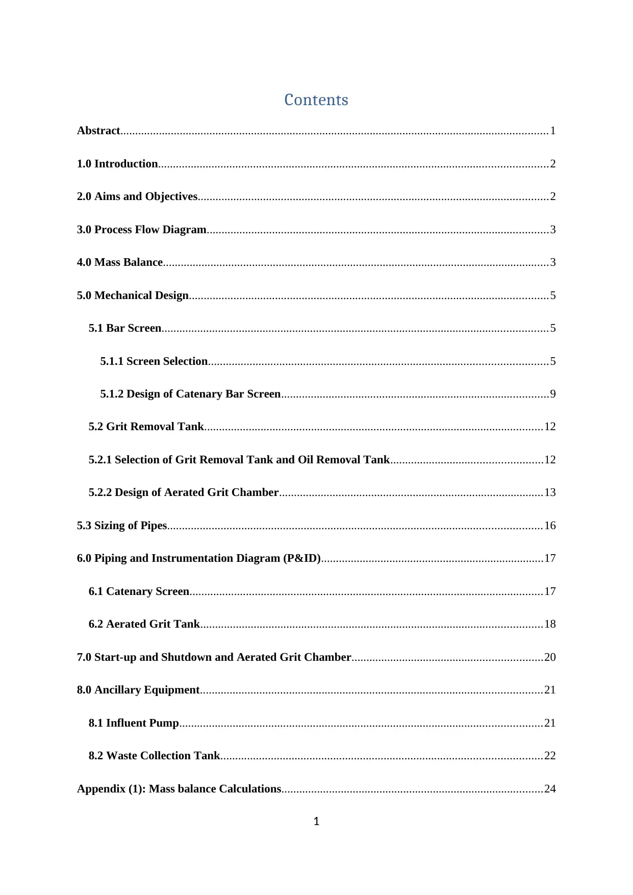
Contents
Abstract................................................................................................................................................1
1.0 Introduction...................................................................................................................................2
2.0 Aims and Objectives......................................................................................................................2
3.0 Process Flow Diagram...................................................................................................................3
4.0 Mass Balance..................................................................................................................................3
5.0 Mechanical Design.........................................................................................................................5
5.1 Bar Screen..................................................................................................................................5
5.1.1 Screen Selection..................................................................................................................5
5.1.2 Design of Catenary Bar Screen..........................................................................................9
5.2 Grit Removal Tank..................................................................................................................12
5.2.1 Selection of Grit Removal Tank and Oil Removal Tank...................................................12
5.2.2 Design of Aerated Grit Chamber.........................................................................................13
5.3 Sizing of Pipes..............................................................................................................................16
6.0 Piping and Instrumentation Diagram (P&ID)...........................................................................17
6.1 Catenary Screen.......................................................................................................................17
6.2 Aerated Grit Tank...................................................................................................................18
7.0 Start-up and Shutdown and Aerated Grit Chamber................................................................20
8.0 Ancillary Equipment...................................................................................................................21
8.1 Influent Pump..........................................................................................................................21
8.2 Waste Collection Tank............................................................................................................22
Appendix (1): Mass balance Calculations........................................................................................24
1
Secure Best Marks with AI Grader
Need help grading? Try our AI Grader for instant feedback on your assignments.
A1.1 Mass balance of Grit Tank (T-102)......................................................................................28
Appendix (2): Mechanical Design calculations................................................................................29
A2.1 Calculations of Catenary bar screen Design............................................................................29
A2.2 Calculations of Aerated Grit Chamber Design...................................................................31
A2.3 Calculations of Oil and Grease Tank..................................................................................33
Appendix (3): Standard Size of carbon Steel Pipe and Calculations....................................................37
Appendix (4): Ancilary Equipment Calculations............................................................................38
A4.1 the Influent Pump....................................................................................................................38
A4.2 Waste Collection Tank (T-111)...............................................................................................39
Reference............................................................................................................................................40
List of figures
Figure 1: The process flow diagram of the designed part of the wastewater treatment plant (Replace
PFD).....................................................................................................................................................5
Figure 2:The classification of used Screens in wastewater treatment as preliminary stage (Metcalf
& Eddy, 2014).......................................................................................................................................8
Figure 3: four main types of mechanically cleaned coarse screen: Chain-driven screen, reciprocating
rake, catenary screen, and continues belt (Qasim, 2017)....................................................................11
Figure 4: Piping and instrumenting Diagram (P&ID) of Catenary Screen (Replace)........................20
Figure 5: Piping and instrumenting Diagram (P&ID) of aerated grit tank (Replace).....................21
Figure 6: The consumption water per capita per one day in 2018 : (Warner et al., 2019).................27
List of tables
Table 1: The summary of the mass balance of the first part of wastewater treatment plant..............6
Table 2: The advantages and disadvantages of types of mechanically cleaned coarse screen
(Metcalf & Eddy, 2014)........................................................................................................................8
Table 3: The summary of result of bar screen design.......................................................................13
Table 4: The comparison of vortex and aerated grit chambers (Metcalf & Eddy, 2013; EPA, 2003). 14
Table 5: The summary of result of design of aerated grit removal tank...........................................17
2
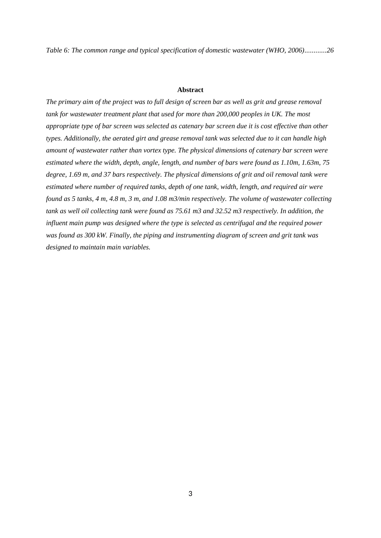
Table 6: The common range and typical specification of domestic wastewater (WHO, 2006)............26
Abstract
The primary aim of the project was to full design of screen bar as well as grit and grease removal
tank for wastewater treatment plant that used for more than 200,000 peoples in UK. The most
appropriate type of bar screen was selected as catenary bar screen due it is cost effective than other
types. Additionally, the aerated girt and grease removal tank was selected due to it can handle high
amount of wastewater rather than vortex type. The physical dimensions of catenary bar screen were
estimated where the width, depth, angle, length, and number of bars were found as 1.10m, 1.63m, 75
degree, 1.69 m, and 37 bars respectively. The physical dimensions of grit and oil removal tank were
estimated where number of required tanks, depth of one tank, width, length, and required air were
found as 5 tanks, 4 m, 4.8 m, 3 m, and 1.08 m3/min respectively. The volume of wastewater collecting
tank as well oil collecting tank were found as 75.61 m3 and 32.52 m3 respectively. In addition, the
influent main pump was designed where the type is selected as centrifugal and the required power
was found as 300 kW. Finally, the piping and instrumenting diagram of screen and grit tank was
designed to maintain main variables.
3
1.0 Introduction
The screening is utilized in the first stage of wastewater treatment as preliminary stage. The
main purpose of the screen is to eliminate large objects (e.g. logs of woods, tires, and concrete blocks)
in order to protect the pump and the mechanical equipment from damage, thus the selected type
should be coarse screen (Qasim, 2017). The elements of screening consist of wires or rods, gratings,
parallel bars, perforated plate, or wire mesh where the shape of the openings can be rectangular or
circular slots. The coarse screen or bar rack composed of parallel rods or bars, coarse screen is utilized
for just eliminating coarse solids (Metcalf & Eddy, 2014).
The grit removal tank is used to remove grit by settlement force where the grit consist of many
materials such as: seed, coffee ground, bone chips, eggshells, glass fragment, soil, stone, sand, gravel,
and cinder. In addition, the same tank removes oil and grease by introducing air into the wastewater,
which enhances the separation of oil from water, then oil and grease floats to the surface of the water
and removed by skimming (EPA, 1995).
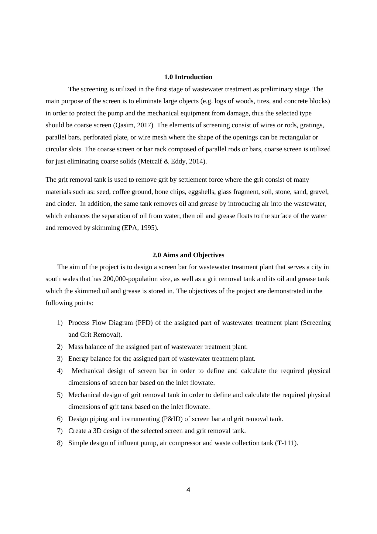
2.0 Aims and Objectives
The aim of the project is to design a screen bar for wastewater treatment plant that serves a city in
south wales that has 200,000-population size, as well as a grit removal tank and its oil and grease tank
which the skimmed oil and grease is stored in. The objectives of the project are demonstrated in the
following points:
1) Process Flow Diagram (PFD) of the assigned part of wastewater treatment plant (Screening
and Grit Removal).
2) Mass balance of the assigned part of wastewater treatment plant.
3) Energy balance for the assigned part of wastewater treatment plant.
4) Mechanical design of screen bar in order to define and calculate the required physical
dimensions of screen bar based on the inlet flowrate.
5) Mechanical design of grit removal tank in order to define and calculate the required physical
dimensions of grit tank based on the inlet flowrate.
6) Design piping and instrumenting (P&ID) of screen bar and grit removal tank.
7) Create a 3D design of the selected screen and grit removal tank.
8) Simple design of influent pump, air compressor and waste collection tank (T-111).
4
Secure Best Marks with AI Grader
Need help grading? Try our AI Grader for instant feedback on your assignments.
3.0 Process Flow Diagram
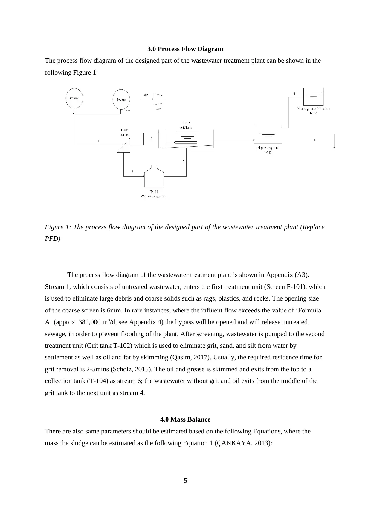
The process flow diagram of the designed part of the wastewater treatment plant can be shown in the
following Figure 1:
Figure 1: The process flow diagram of the designed part of the wastewater treatment plant (Replace
PFD)
The process flow diagram of the wastewater treatment plant is shown in Appendix (A3).
Stream 1, which consists of untreated wastewater, enters the first treatment unit (Screen F-101), which
is used to eliminate large debris and coarse solids such as rags, plastics, and rocks. The opening size
of the coarse screen is 6mm. In rare instances, where the influent flow exceeds the value of ‘Formula
A’ (approx. 380,000 m3/d, see Appendix 4) the bypass will be opened and will release untreated
sewage, in order to prevent flooding of the plant. After screening, wastewater is pumped to the second
treatment unit (Grit tank T-102) which is used to eliminate grit, sand, and silt from water by
settlement as well as oil and fat by skimming (Qasim, 2017). Usually, the required residence time for
grit removal is 2-5mins (Scholz, 2015). The oil and grease is skimmed and exits from the top to a
collection tank (T-104) as stream 6; the wastewater without grit and oil exits from the middle of the
grit tank to the next unit as stream 4.
4.0 Mass Balance
There are also same parameters should be estimated based on the following Equations, where the
mass the sludge can be estimated as the following Equation 1 (ÇANKAYA, 2013):
5
Mass of sludge=TSS∗Q
100 (1)
Where: (TSS : total suspended solid in mg/L (PPM), and Q : the volumetric flowrate of inlet
wastewater). The mass of volatile suspended solid can be estimated based on the following Equation 2
(ÇANKAYA, 2013):
Mass of VSS= VSS∗Q
100 (2)
Where: ( VSS : volatile suspended solid in mg/L (PPM), and Q : the volumetric flowrate of inlet
wastewater). The mass of BOD (biochemical oxygen demand) which refers to the required amount of
oxygen that would be consumed if all the organic materials, so it is an indicator for the amount of
organic matters in water. It is can be estimated based on the following Equation 3 (ÇANKAYA,
2013):
Mass of BOD= BOD∗Q
100 (3)
Where: (BOD : biochemical oxygen demand in mg/L (PPM), and Q : the volumetric flowrate of inlet
wastewater). The oil and grace can be estimated based on the following Equation 4:
Mass of OIL=oil conentration∗Q
100 (4)
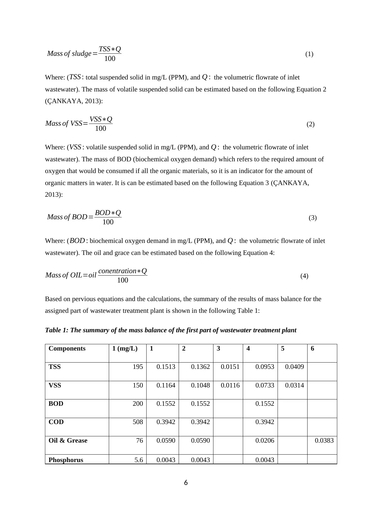
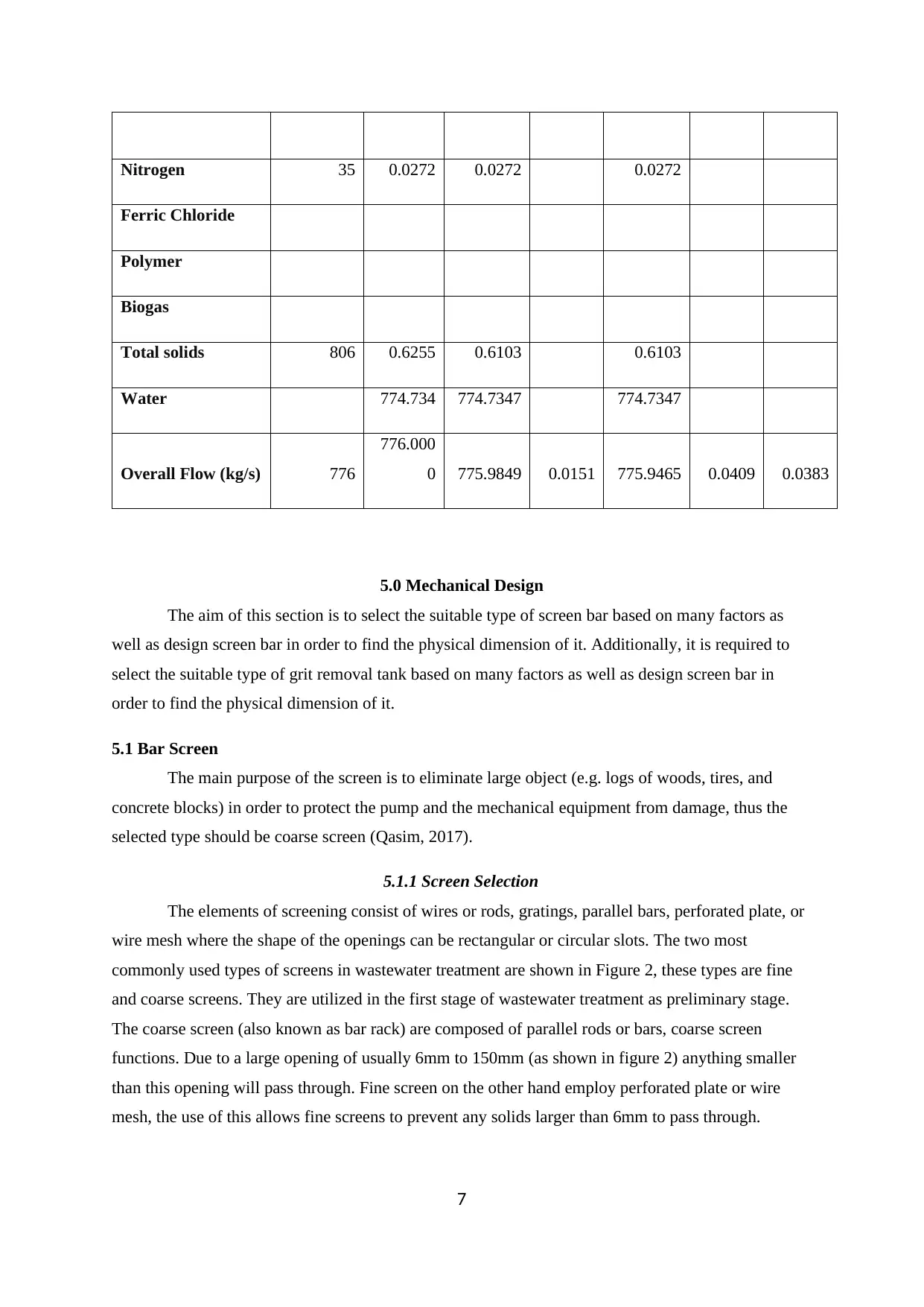
Based on pervious equations and the calculations, the summary of the results of mass balance for the
assigned part of wastewater treatment plant is shown in the following Table 1:
Table 1: The summary of the mass balance of the first part of wastewater treatment plant
Components 1 (mg/L) 1 2 3 4 5 6
TSS 195 0.1513 0.1362 0.0151 0.0953 0.0409
VSS 150 0.1164 0.1048 0.0116 0.0733 0.0314
BOD 200 0.1552 0.1552 0.1552
COD 508 0.3942 0.3942 0.3942
Oil & Grease 76 0.0590 0.0590 0.0206 0.0383
Phosphorus 5.6 0.0043 0.0043 0.0043
6
Nitrogen 35 0.0272 0.0272 0.0272
Ferric Chloride
Polymer
Biogas
Total solids 806 0.6255 0.6103 0.6103
Water 774.734 774.7347 774.7347
Overall Flow (kg/s) 776
776.000
0 775.9849 0.0151 775.9465 0.0409 0.0383
5.0 Mechanical Design
The aim of this section is to select the suitable type of screen bar based on many factors as
well as design screen bar in order to find the physical dimension of it. Additionally, it is required to
select the suitable type of grit removal tank based on many factors as well as design screen bar in
order to find the physical dimension of it.
5.1 Bar Screen
The main purpose of the screen is to eliminate large object (e.g. logs of woods, tires, and
concrete blocks) in order to protect the pump and the mechanical equipment from damage, thus the
selected type should be coarse screen (Qasim, 2017).
5.1.1 Screen Selection
The elements of screening consist of wires or rods, gratings, parallel bars, perforated plate, or
wire mesh where the shape of the openings can be rectangular or circular slots. The two most
commonly used types of screens in wastewater treatment are shown in Figure 2, these types are fine
and coarse screens. They are utilized in the first stage of wastewater treatment as preliminary stage.
The coarse screen (also known as bar rack) are composed of parallel rods or bars, coarse screen
functions. Due to a large opening of usually 6mm to 150mm (as shown in figure 2) anything smaller
than this opening will pass through. Fine screen on the other hand employ perforated plate or wire
mesh, the use of this allows fine screens to prevent any solids larger than 6mm to pass through.
7
Paraphrase This Document
Need a fresh take? Get an instant paraphrase of this document with our AI Paraphraser
Finally micro-screens, operate on a microscopic level, only particulate matter smaller than 0.5
micrometers can pass through. (Metcalf and Eddy, 2014).
Figure 2:The classification of used Screens in wastewater treatment as preliminary stage (Metcalf
& Eddy, 2014)
Since the main purpose of the screen is to eliminate large object (e.g. logs of woods, tires, and
concrete blocks) in order to protect the pump and the mechanical equipment from damage, thus the
selected type should be coarse screen (Qasim, 2017). Since the number of population is over 20,000
(i.e. large wastewater treatment plant) and the wastewater has sludge, so the used type is coarse screen
(i.e. bar screen) is used (EPA, 1995). The hand cleaned coarse screen can only be used for small
wastewater pumping stations (Qasim, 2017); therefore, the mechanically cleaned coarse screen is
used.
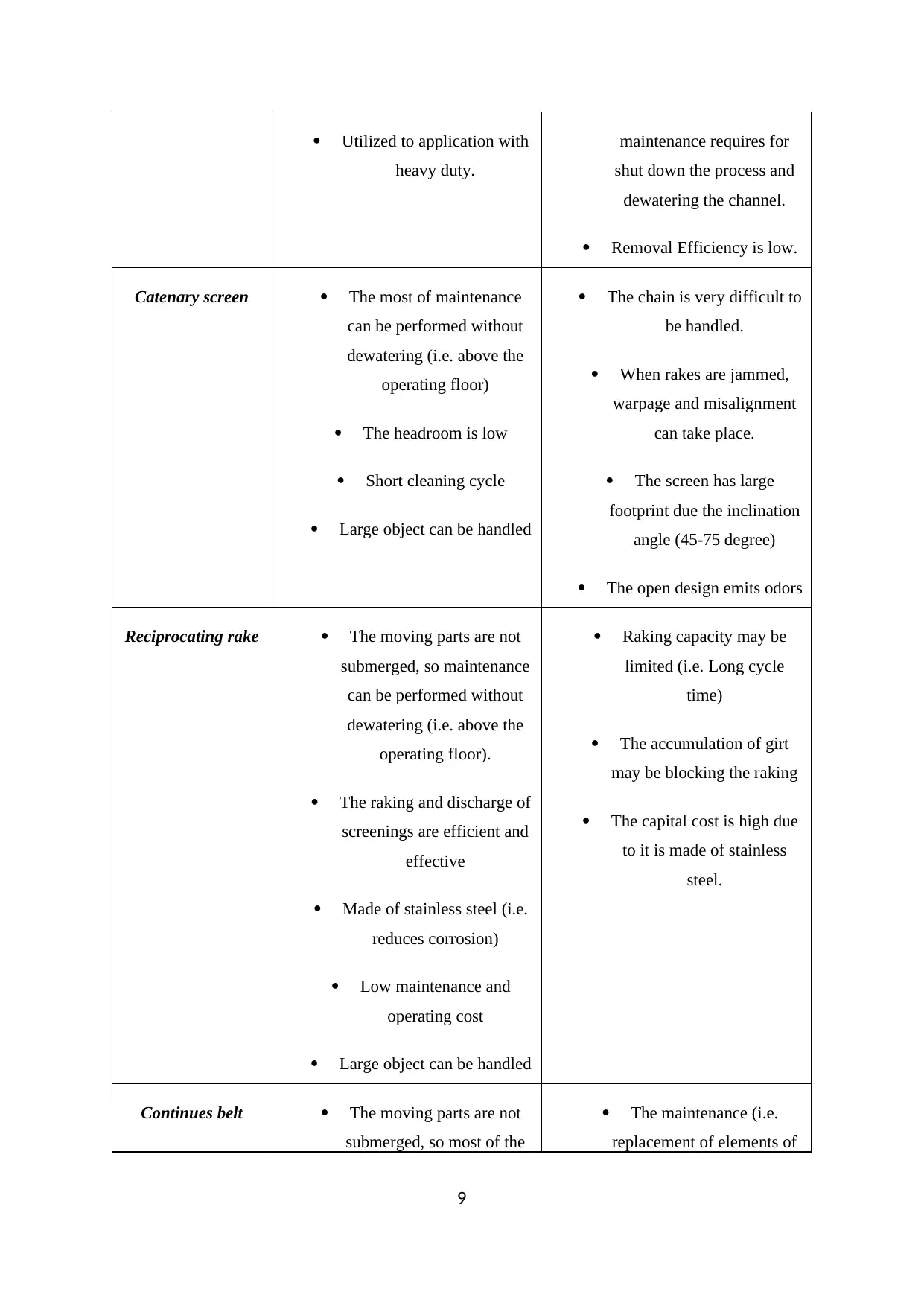
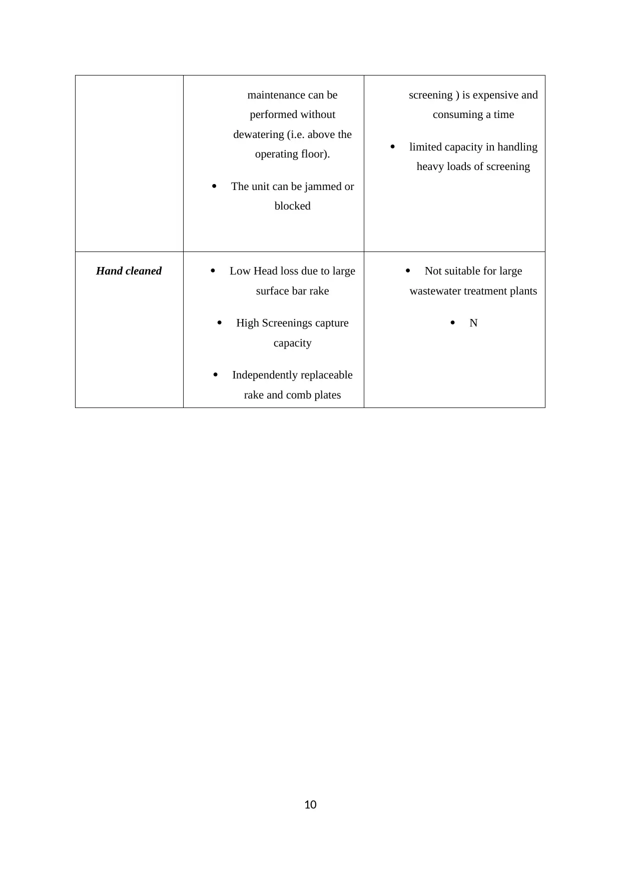
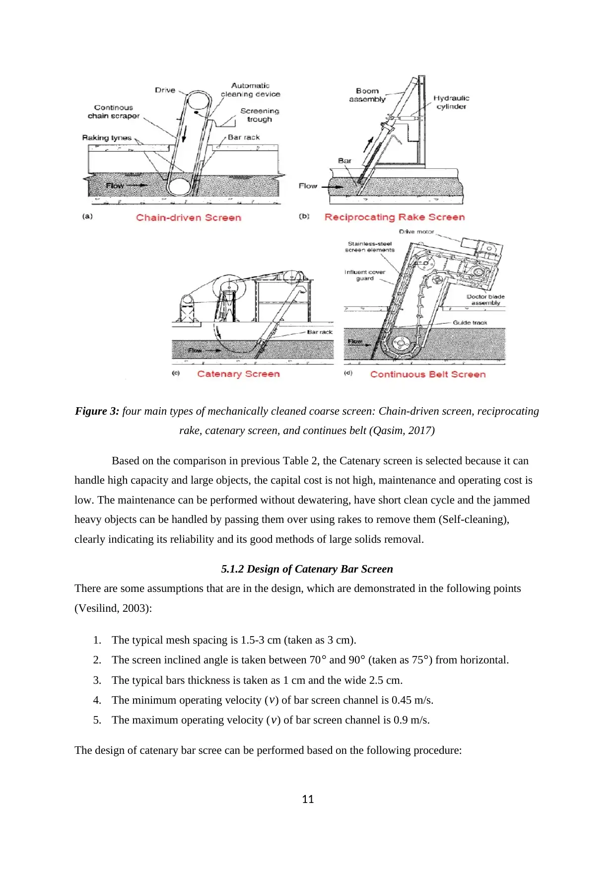
As shown in Figure 2, there are four main types of mechanically cleaned coarse screen:
Chain-driven screen, reciprocating rake, catenary screen, and continues belt. To select the suitable
type of screen, it has to study the advantages and disadvantages of each types where it can be
demonstrated as following Table 2 (Metcalf & Eddy, 2014):
Table 2: The advantages and disadvantages of types of mechanically cleaned coarse screen
(Metcalf & Eddy, 2014)
Types of Screen Advantages Disadvantages
Chain-driven
screen
Short cleaning cycle. The moving parts are
submerged, so the
8
Utilized to application with
heavy duty.
maintenance requires for
shut down the process and
dewatering the channel.
Removal Efficiency is low.
Catenary screen The most of maintenance
can be performed without
dewatering (i.e. above the
operating floor)
The headroom is low
Short cleaning cycle
Large object can be handled
The chain is very difficult to
be handled.
When rakes are jammed,
warpage and misalignment
can take place.
The screen has large
footprint due the inclination
angle (45-75 degree)
The open design emits odors
Reciprocating rake The moving parts are not
submerged, so maintenance
can be performed without
dewatering (i.e. above the
operating floor).
The raking and discharge of
screenings are efficient and
effective
Made of stainless steel (i.e.
reduces corrosion)
Low maintenance and
operating cost
Large object can be handled
Raking capacity may be
limited (i.e. Long cycle
time)
The accumulation of girt
may be blocking the raking
The capital cost is high due
to it is made of stainless
steel.
Continues belt The moving parts are not
submerged, so most of the
The maintenance (i.e.
replacement of elements of
9
maintenance can be
performed without
dewatering (i.e. above the
operating floor).
The unit can be jammed or
blocked
screening ) is expensive and
consuming a time
limited capacity in handling
heavy loads of screening
Hand cleaned Low Head loss due to large
surface bar rake
High Screenings capture
capacity
Independently replaceable
rake and comb plates
Not suitable for large
wastewater treatment plants
N
10
Secure Best Marks with AI Grader
Need help grading? Try our AI Grader for instant feedback on your assignments.
Figure 3: four main types of mechanically cleaned coarse screen: Chain-driven screen, reciprocating
rake, catenary screen, and continues belt (Qasim, 2017)
Based on the comparison in previous Table 2, the Catenary screen is selected because it can
handle high capacity and large objects, the capital cost is not high, maintenance and operating cost is
low. The maintenance can be performed without dewatering, have short clean cycle and the jammed
heavy objects can be handled by passing them over using rakes to remove them (Self-cleaning),
clearly indicating its reliability and its good methods of large solids removal.
5.1.2 Design of Catenary Bar Screen
There are some assumptions that are in the design, which are demonstrated in the following points
(Vesilind, 2003):
1. The typical mesh spacing is 1.5-3 cm (taken as 3 cm).
2. The screen inclined angle is taken between 70 ° and 90° (taken as 75°) from horizontal.
3. The typical bars thickness is taken as 1 cm and the wide 2.5 cm.
4. The minimum operating velocity ( v) of bar screen channel is 0.45 m/s.
5. The maximum operating velocity ( v) of bar screen channel is 0.9 m/s.
The design of catenary bar scree can be performed based on the following procedure:
11
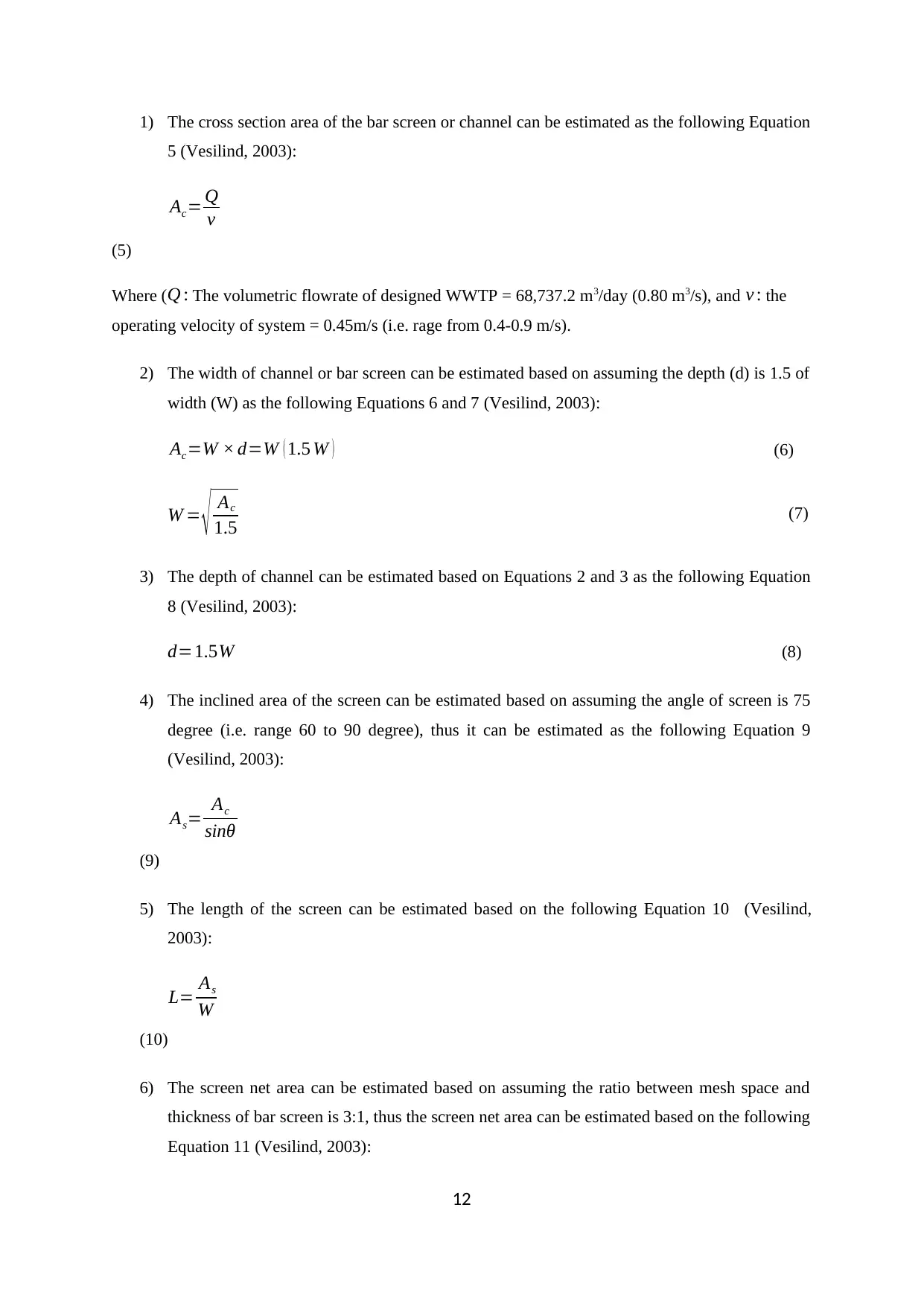
1) The cross section area of the bar screen or channel can be estimated as the following Equation
5 (Vesilind, 2003):
Ac= Q
v
(5)
Where ( Q : The volumetric flowrate of designed WWTP = 68,737.2 m3/day (0.80 m3/s), and v : the
operating velocity of system = 0.45m/s (i.e. rage from 0.4-0.9 m/s).
2) The width of channel or bar screen can be estimated based on assuming the depth (d) is 1.5 of
width (W) as the following Equations 6 and 7 (Vesilind, 2003):
Ac=W × d=W ( 1.5 W ) (6)
W = √ Ac
1.5 (7)
3) The depth of channel can be estimated based on Equations 2 and 3 as the following Equation
8 (Vesilind, 2003):
d=1.5W (8)
4) The inclined area of the screen can be estimated based on assuming the angle of screen is 75
degree (i.e. range 60 to 90 degree), thus it can be estimated as the following Equation 9
(Vesilind, 2003):
As= Ac
sinθ
(9)
5) The length of the screen can be estimated based on the following Equation 10 (Vesilind,
2003):
L= As
W
(10)
6) The screen net area can be estimated based on assuming the ratio between mesh space and
thickness of bar screen is 3:1, thus the screen net area can be estimated based on the following
Equation 11 (Vesilind, 2003):
12
Anet = As ( S
S+ tb ) (11)
7) The required number of bars for the screen can be estimated based on mesh spacing and width
of the screen as the following Equation 12 (Vesilind, 2003):
Nb =W
S
(12)
Based on the pervious procedure and calculation in Appendix 2, the summary of result of bar screen
design can be shown as follows Table 3:
Table 3: The summary of result of bar screen design
Parameters Value Unit
Design volumetric flowrate of WWTP (QF ¿ 0.80 m3/s
Design assumed operation velocity (v) 0.45 m/s
The cross-sectional area of bar screen (Ac) 1.78 m2
The width of bar screen or channel (w) 1.10 m
The water depth of the channel (d) 1.63 m
The angle of the screen from horizontal ( θ) 75 °degree
The inclined area of screen ( As) 1.83 m2
The net area of screen ( Anet ) 1.37 m2
Length of the screen or channel (L) 1.67 m
Material construction of bar Carbon steel
Mesh Space (S) 3 cm
Bar thickness (tb) 1 cm
13
Paraphrase This Document
Need a fresh take? Get an instant paraphrase of this document with our AI Paraphraser
Number of bars ( Nb) 37 -
5.2 Grit Removal Tank
The grit removal tank is used to remove grit by settlement force where the grit consist of
many materials such as: seed, coffee ground, bone chips, eggshells, glass fragments, soil, stone, sand,
gravel, and cinder (EPA, 1995).
5.2.1 Selection of Grit Removal Tank and Oil Removal Tank
There are three main types of grit removal tank: horizontal flow grit flow chamber (i.e. square
and rectangular), aerated grit chamber, and vortex grit chamber. The horizontal flow grit flow
chamber becomes limited used recently in favor of vortex and aerated grit chambers (Metcalf & Eddy,
2013), thus the comparison between the latter two types should be applied. The comparison of vortex
and aerated grit chambers can be presented as following Table 4 (EPA, 2003):
Table 4: The comparison of vortex and aerated grit chambers (Metcalf & Eddy, 2013; EPA, 2003)
Types of
grit tank
Advantages Disadvantages
Vortex grit
chamber
Consistent removal efficiency along various
ranges of flowrate
The moving parts are not submerged, so the
maintenance requires is easy without
dewatering
The size of vortex is small compared with
other types.
It can remove high amounts of fine particles
above than 73%.
High capital cost
High maintenance cost
The open design emits odors
Required a derating
modifications are difficult
The grit sump is clogging
Aerated
grit
chamber
low putrescible content of organic may be
eliminated
Consistent removal efficiency along various
ranges of flowrate
It is versatile type where mixing, pre-aeration,
and chemical adding (e.g. flocculation) to
enhance the performance.
High capital cost, it is higher
than vortex type by 7-10 times
Higher energy requirement
than vortex type by 10 times
Higher maintenance and
operating cost than vortex type.
The open design emits odors
14
The downstream unit performance can be
increased using pre-aeration
due to volatile organic matters
Based on the pervious comparison table, although the vortex grit removal tank is more
suitable than aerated grit removal tank for small WWTP in terms of the capital, energy, operating, and
maintenance cost but aerated grit chamber is selected because the process has high duty. The aerated
grit and grease removal tank can be shown as follows Figure 4:
Figure 4: The aerated grit and grease removal tank where oil and grease are skimmed (Marais et
al., 1996)
5.2.2 Design of Aerated Grit Chamber
There are some assumptions should be applied in the design, which is demonstrated as follow (Marais
et al., 1996):
1) The influent operating design velocity can be taken in the range 0.15-0.9 m/s (i.e. it is
assumed as 0.5 m/s).
2) The depth can be taken as 2-5 m (taken as 4 m).
3) The ratio of the depth of channel to width of channel can be taken as 1:1.2.
4) The dentation time of the process can be taken 2-5 minutes (i.e. it can be taken as 3 minutes).
5) The peak factor can be taken as 2.
6) The length of air supply can be taken as 0.3 m3/min.m
Based on the pervious assumptions, the design of sedimentation tank can be performed as following
procedure (Marais et al., 1996): (Calculation in Appendix 2)
15
1) The required peak flow of the system can be estimated as the following Equation 13:
QPF= peak factor∗Q
(13)
QPF=1.6 m3 /s
2) The required total volume of grit chambers can be estimated based on following Equation 14:
V =QPF td
(14)
V =288 m3
3) The volume of one chamber of grit removal is taken as maximum equal to 60 m3, So, number
of chambers can be calculated as follow Equation 15:
V Unit= V tot
N ≤ 60 m3
(15)
V Unit=4.8take 5
The volume of each grit tank can be estimated based on providing 5 chambers in order to
facilitate periodic maintenance and cleaning, thus the volume of one chamber can estimated as the
following formula:
V Unit =57.6 m3
4) The width of one chamber can be estimated based on assuming the depth can be taken as 4 m
and ratio of the depth of channel to width of channel can be taken as 1:1.2, so it can be
estimated as the following Equation 16:
W =1.2 d (16)
W =4.8 m
The calculated width is acceptable due to the range of standard length is between 2.5 to 7 m.
5) The required length of one grit chamber can be estimated as the following Equation 17:
16
Secure Best Marks with AI Grader
Need help grading? Try our AI Grader for instant feedback on your assignments.
L= V unit
W . d
(17)
L=3 m
Increase the required length 20% to account the outlet and inlet conditions, the actual length can be
found as the following formula:
La=3.6 m
The calculated length is acceptable due to the range of standard length is between 3 to 20 m.
6) The required volumetric flowrate of air can be estimated based on assuming length of air
supply can be taken as 0.3 m3/min.m, thus it can be found as the following Equation 18:
Qair=0.3 La (18)
Qair=1.08 m3 /min
7) Check the surface overflow rate (SOR), which can be estimated based on the following Equation
19, where the surface area of overflow can be found as follows Equation 20:
SOR= QPF
no . of used tank∗W . d
(19)
SOR=0.017 m/s (1.67 cm/s )
The settling velocity of the smallest particle was found as 2.4 cm/s, the found SOR value is less than
2.4 cm/s, therefore the design is safe.
A= Q
SOR
(20)
A=48 m2
The summary of results for the design of aerated grit removal tank are shown in the following Table
5:
17
Table 5: The summary of result of design of aerated grit removal tank
Parameters Values Units
Design volumetric flowrate of WWTP 1.60 m3/s
Retention time (tr) 3.0 min
Design assumed operation velocity 0.50 m/s
Designed peak flowrate 2 m3/s
Total volume of chambers 288 m3
Number of used chambers 5 -
Volume of one tank 57.6 m3
The width of one chamber 4.8 m
The water depth of one chamber (d) 4 m
The length of one chamber 3 m
The required flowrate of air 1.08 m3/min
SOR 1.67 Cm/s
The surface area of overflow 48 m2
It is worth mentioning that the last tank of 5 chambers can be only used for oil removing.
5.3 Sizing of Pipes
Since the inlet and outlet of screen as well as aerated grit removal tank is about the same
flowrate, so the same calculations for streams 1, 2, and 4 can be applied as following steps:
The required nominal size of pipes can be estimated flowrate (i.e. 0.796 m3 /s ¿ and assumed velocity
of wastewater (2 m/s) as follows Equation 27 (Sinnott, & Towler, 2019):
Ns = √ 4 q
π vm
(27)
18
Ns =711.67 mm(28.02 inch)
According to standard ANSI B36.10 for carbon steel pipes (i.e. see Table and calculations in
Appendix 3) and based on the found nominal size of pipes, the taken nominal size is 30 inch where
the outside diameter is 762 mm. In addition, the schedule can be selected as STD due to the lower
available schedule where the thickens is found as 9.53 mm. Thus, the inner diameter of pipe can be
found as the following Equation 28 (Sinnott, & Towler, 2019):
Do =D−2 t (28)
Do =742.94 mm
6.0 Piping and Instrumentation Diagram (P&ID)
The objective of this section is to analyze, find, and design a control system for catenary
screen and grit tank for wastewater treatment plant in order to control the main variables of the
process to ensure optimum operating conditions and to make sure that there are no mechanical
multifunction and the target amount is treated. See Appendix 5
6.1 Catenary Screen
The degree of freedom of this unit can be estimated as follows:
DOF=¿ of unknowns−¿ of equations (29)
DOF=5 ( F¿ , Fwaste , Fwater , X¿ , XWater )−2 ( Mass balances ) =3 controllers
Feed flow, flow of filtrate and level of waste on the mesh are the control variables.
The designed piping and instrumenting diagram of bar screen can be shown in following Figure 5,
where there are just three variables should be controlled (i.e. inlet flowrate of wastewater, liquid level
before screen, and liquid level after screen). Each control system or loop has the same components:
measuring unit, transmitter, indicator and controller, and control valve. The description of each
control system can be performed as follows:
19
Paraphrase This Document
Need a fresh take? Get an instant paraphrase of this document with our AI Paraphraser
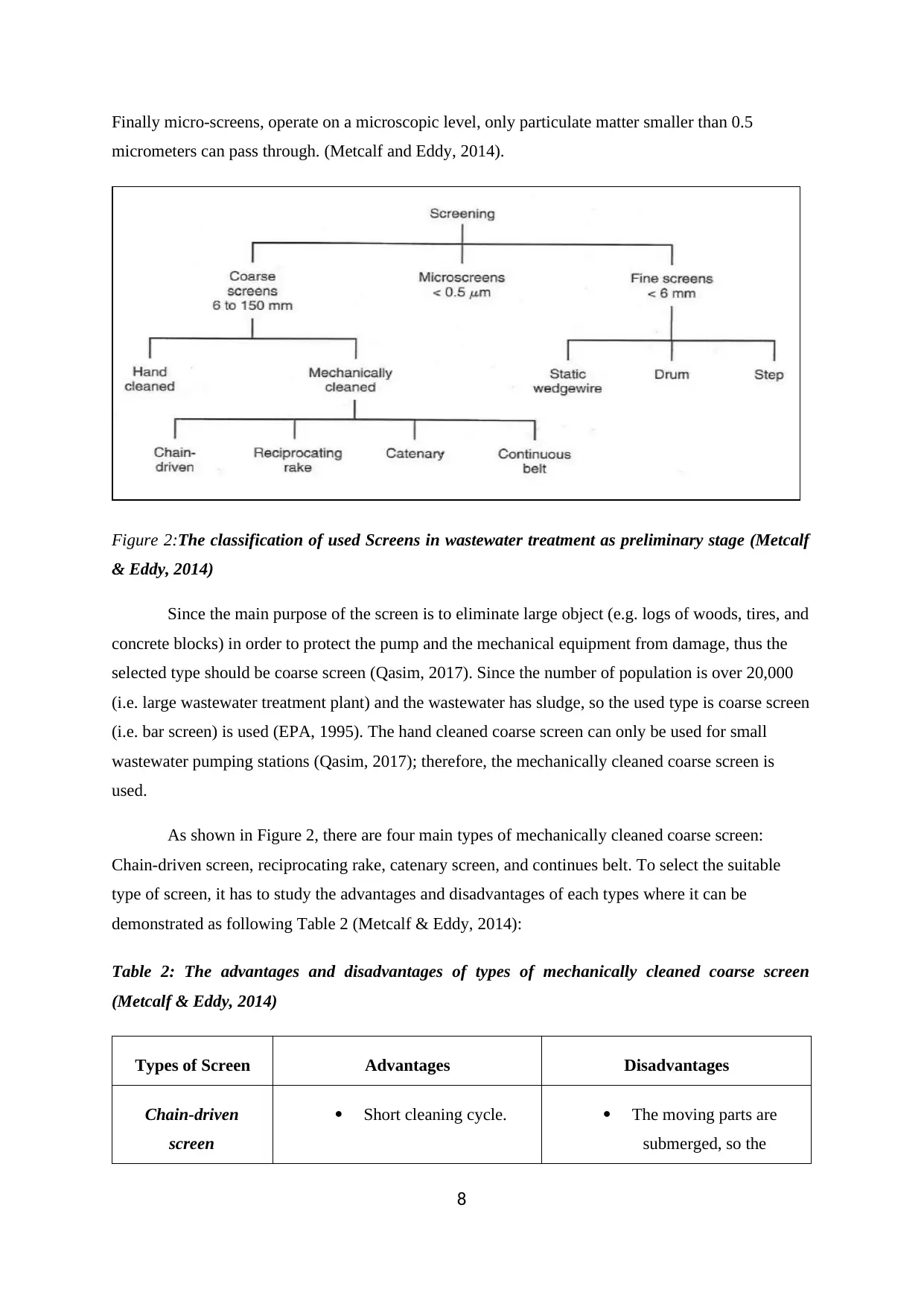
Figure 4: Piping and instrumenting Diagram (P&ID) of Catenary Screen (Replace)
The inlet flowrate can be measured by flowrate meter (FM) as normal reading and then send
it to the flow transmitter (FT). The flow transmitter (FT) can convert the normal reading to electrical
signal and then send it to the flow indicator and controller (FIC). FIC is received the electrical signal
to compare the found reading with set value and then take appropriate action as pneumatic (i.e. air or
oil) pressure. The pneumatic pressure can open more or close more the control valve (V-51) to
introduce more flowrate or decrease the inlet amount of wastewater flowrate.
The up or down liquid level control systems can work as the same sequences; the liquid level
before or after the screen is measured by Float Liquid Level Gauge (LM) and then send it to the level
transmitter (LT). LT can convert the normal reading to electrical signal and then send it to the level
indicator and controller (LIC). LIC is received the electrical signal to compare the found reading with
set value and then take appropriate action as pneumatic (i.e. air or oil) pressure. The pneumatic
pressure can open more or close more the control valve (V-56 before screen or V-54 after screen) to
increase or decrease the liquid level.
6.2 Aerated Grit Tank
The degree of freedom of this unit can be estimated as follows:
20
DOF=¿ ofunknowns−¿ of equations (30)
DOF=5 ( F¿ , Ftop , Fbottom , speed of motor ) −1 ( Mass balances ) =3 controllers
Feed flow, flow of top and level in the tank are the control variables.
The designed piping and instrumenting diagram of aerated grit tank can be shown in
following Figure 6, where there are just three variables should be controlled (i.e. inlet flowrate of air
based the inlet flowrate of wastewater, liquid level of tank, and the exit flowrate of treated
wastewater). Each control system or loop has the same components: measuring unit, transmitter,
indicator and controller, and control valve. The description of each control system can be performed
as follows:
Figure 5: Piping and instrumenting Diagram (P&ID) of aerated grit tank (Replace)
The first control system is used to adjust the inlet flowrate of wastewater as required and the
inlet air inside the aerated grit tank. The inlet wastewater can be measured by flowrate meter (FM) as
normal reading and then send it to the flow transmitter (FT). The flow transmitter (FT) can convert
the normal reading to electrical signal and then send it to the flow indicator and controller (FIC) and
air motor. The air motor inlet the required amount of air based on the inlet wastewater flowrate. FIC is
received the electrical signal to compare the found reading with set value and then take appropriate
21
action as pneumatic (i.e. air or oil) pressure. The pneumatic pressure can open more or close more the
control valve (V-36) to introduce more flowrate or decrease the inlet amount of wastewater flowrate.
The second control system is liquid level control systems, which can work as the same
sequences; the liquid level inside the tank is measured by Float Liquid Level Gauge (LM) and then
sends it to the level transmitter (LT). LT can convert the normal reading to electrical signal and then
send it to the level indicator and controller (LIC). LIC is received the electrical signal to compare the
found reading with set value and then take appropriate action as pneumatic (i.e. air or oil) pressure.
The pneumatic pressure can open more or close more the control valve (V-41) to increase or decrease
the liquid level.
The third control system is used to adjust the outlet flowrate of treated wastewater as
required. The outlet flowrate of treated wastewater can be measured by flowrate meter (FM) as
normal reading and then send it to the flow transmitter (FT). The flow transmitter (FT) can convert
the normal reading to electrical signal and then send it to the flow indicator and controller (FIC). FIC
is received the electrical signal to compare the found reading with set value and then take appropriate
action as pneumatic (i.e. air or oil) pressure. The pneumatic pressure can open more or close more the
control valve (V-44) to introduce more flowrate or decrease the inlet amount of wastewater flowrate.
The safety in a control system is important for some critical variables. In this case, the alarm
could be installed on the mesh of screen to indicate a problem of blocking in the mesh by measuring
the pressure. In the other hand, the wastewater is considered a critical material in term of infection and
pollution. So, it is preferred to use high level alarm to indicate the flooding of the tank to avoid flow
over of wastewater to the soil and ground water.
7.0 Start-up and Shutdown and Aerated Grit Chamber
The start-up procedure of any equipment is extremely serious and important to reach steady state
situation in short time and without any multifunction of instruments (i.e. motor and pumps). The start-
up of the aerated grit chamber can be demonstrated as follows steps:
1) Check all electric cables, mechanical instrument, automatic and manual valves, control
sensors, and leakage of any pipe or joints.
2) Clean pipes and tank using water through opening globe valve (V-40) to disposal the cleaning
water.
3) Open inlet valves (V-37 and V-38) and inlet pump to introduce the wastewater to the tank and
wait till the tank is filled with wastewater.
22
Secure Best Marks with AI Grader
Need help grading? Try our AI Grader for instant feedback on your assignments.
4) Open all bottom exit valves (V-42 and V-43) as well as top exit valves (V-45 and V-47) to
exit the treated water and water with grit.
The shutdown procedure of any equipment is extremely serious and important to close the
equipment in short time and without any multifunction of instruments (i.e. motor and pumps). The
shutdown of the aerated grit chamber can be demonstrated as follows steps:
1) Close inlet valves (V-37 and V-38) and inlet pump and wait until the tank empty.
2) Close all bottom exit valves (V-42 and V-43) as well as top exit valves (V-45 and V-47).
3) Clean pipes and tank using water through opening globe valve (V-40) to disposal the cleaning
water.
4) Check all electric cables, mechanical instrument, automatic and manual valves, control sensors,
and leakage of any pipe or joints.
8.0 Ancillary Equipment
The aim of this part is to design simply for the influent pump of wastewater treatment plant as
well as design the waste collection tank (T-111).
8.1 Influent Pump
There are main two types of pumps used in chemical industries: centrifugal pump and positive
displacement pump. The centrifugal pump used for wastewater while the positive displacement pump
used for sludge handling due to positive displacement pump is more perfect with viscous liquid than
centrifugal pump. In addition, centrifugal pump can handle with large capacities of liquid than
positive displacement type as well as it has lower capital and operating cost (Serdarevic et al, 2018).
The required power of inlet pump station can be found based on the following procedure: (calculation
in Appendix 4)
1) The theoretical power of pump station can be estimated based on the inlet flowrate density of
wastewater (i.e. 1000 kg/m3) and height which can be assumed 25 m (i.e. 4 m of grit tank and
other can be assumed in screen and pipes). It can be calculated as following Equation 29 (Sinnott,
& Towler, 2019):
P=Qρ g H (29)
P=195.11 kW
2) The actual required power of influent pump can be estimated based on assuming efficiency of
centrifugal pump as follows Equation 30 (Sinnott, & Towler, 2019):
23
Pa= P
η
(30)
Pa=300.17 kW
8.2 Waste Collection Tank
The wastewater collection tank is designed to find the physical dimension where the following step
should be followed:
1) The required volume of wastewater collection tank can be determined based on the assumed
storage time (1 day) and volumetric flowrate (assumed 0.01% losses of flowrate) as follows
Equation 31 (Marais et al., 1996):
V =q∗t (31)
V =68.74 m3
Add 10% extra volume for future expansion and safety purpose, so the actual volume become as
follows formula:
V a =75.61m3
2) The inner diameter of the tank can be determined based on assuming the height is double the
diameter, thus the diameter can be found as follows Equation 32 (Marais et al., 1996):
D= 3
√ 2V a
π (32)
D=3.64 m
3) Based on the pervious assumption and found diameter, the height of cylindrical tank can be found
as follows Equation 33 (Marais et al., 1996):
H=2 D (33)
H=7.26 m
24
Conclusion
The basic aim of the project was to find suitable type and the optimum physical dimension of bar
screen as well as grit and grease removal tank based on standard design. The mass balance of the
wastewater treatment plant was performed based on literature review. The type of bar screen was
selected as catenary screen due to it can handle high capacity and large objects, the capital cost is not
high, and maintenance and operating cost is low. The required cross section area of catenary screen
was found as 1.77 m2 while the width and depth were found as 1.10 m and 1.63 m respectively. The
screen net area was found as 1.37 m2 and the mesh was selected as 3 mm, so the number of required
of bar was found as 37. The type of grit and oil removal tank was selected as aerated grit and grease
removal tank due to it can handle high amount of wastewater. Based on the design, the actual required
volume of one aerated grit and grease removal tank was found 57.6 m3 where the required number of
tanks was found 5. The depth, width, and length of each aerated grit and grease removal tank was
found as 4 m, 4.8 m, and 3 m respectively. Additionally, the required flowrate of air was found as
1.08 m3/min in order to remove grease and oil. The oil and grease colleting tank was design where
the required volume was found as 32.52 m3 where the diameter, height, and thickens were found as
2.75 m, 5.50 m, and 3 mm. The two main inlet and outlet pipes were sized where the required
nominal size was found as 30 inch. The piping and instrumenting diagram of screen and grit removal
tank were designed to control main variables of the process. Finally, the influent main pump was
designed where the type is selected as centrifugal and the required power was found as 300 kW, as
well as the required volume wastewater collecting was found as 75.61 m3 (i.e. D=3.64 m and H=7.28
m).
25
Paraphrase This Document
Need a fresh take? Get an instant paraphrase of this document with our AI Paraphraser
Appendix (1): Mass balance Calculations
The domestic wastewater comes from many sources such as: household activity, institutions, and
commercial and business buildings as well as water come from storm and rain. Thus, the common
range and typical specification of domestic wastewater can be presented as the following Table
(WHO, 2006):
Table 6: The common range and typical specification of domestic wastewater (WHO, 2006)
The domestic flows are often estimated based on a flow per head of served population per day (i.e.
empirical data method). The quantity of water used per head per day varies between countries, mainly
as a function of degree of industrialization. The consumption of water consumption per capita per one
day can be shown as the following Figure (Warner et al., 2019):
26
Figure 6: The consumption water per capita per one day in 2018 : (Warner et al., 2019)
Formulas for Estimating Key Parameters relating to Quantity of Wastewater
Base flow rate that is adopted can be estimated based on the following Equation 1:
DWF=PG+ I +E (1)
Where: (DWF = Dry weather flow, P = Population, G = Flow per capita, I = Infiltration, and E =
Industrial waste)
Normally there would be an industrial flow component in the equation but the brief specifies domestic
use so industrial flows can be neglected (E=0), so the final formula can be shown as following
Equation 2:
DWF=PG+ I (2)
As DWF is rarely a reality, ADWF (average dry weather flow) should be used, where it is as
1.25DWF, so the final formula can be presented as following Equation 3:
ADWF=1.25(PG + I ) (3)
The maximum storm flow received at a treatment works is calculated by a formula known as Formula
‘A’. This sets the minimum level at which the wastewater is sufficiently diluted by rainwater so as to
27
avoid pollution of the receiving watercourse when overflowed from the sewer. It is known as
‘Formula A’, so it can be estimated though the following Equation 4:
Formula A=DWF+ 1.36 P (4)
The maximum rate of flow accepted for settlement and biological treatment at a wastewater works is
defined as the Flow to Full Treatment (FFT) and it is this flow that is used to design hydraulic
processes. FFT represents the economical and practical cut-off for treatment; the difference between
Formula A and FFT is stored on-site or in the sewerage system until the rate of flows return to
ADWF. Flows above FFT will be overflowed if storm flows last for longer than a set period of time
(usually 2 hours). Overflow is normally from settlement tanks (Storm Tanks). Generally, it can be
estimated based on the following Equation 5:
FFT =3 DWF (5)
A peaking factor (PF) is used in wastewater treatment as it is difficult to compare peak flow values
across different plants, which can be estimated as the following Equation 6:
PF=Peak Flowrate/ Long Term Average Flowrate (6)
This formula in conjunction with the briefing and research figures (population size used is 240,000 to
allow for population growth):
DWF = 240,000*149 + 0.5(240,000*149)
DWF = 53,640 m3/d (621 L/s)
ADWF = 1.25*53,640
ADWF = 67,050 m3/d (776 L/s)
PF = 2.5*67,050
PF = 167,625 m3/d (1940 L/s)
Formula A = 53,640 + 1.36*240,000
Formula A = 380,040 m3/d (4,399 L/s)
FFT = 3*53,640
FFT = 160,920 m3/d (1863 L/s)
28
Secure Best Marks with AI Grader
Need help grading? Try our AI Grader for instant feedback on your assignments.
Normally, the flow to full treatment value would be used as the basis for design calculations.
However, due to the equalization basin/overflow tank set up, the flow rate can be maintained as the
ADWF of 776 L/s. Unit operations upstream of the equalization basin have been designed on the basis
of peak flow.
The calculation of each stream of the first part of wastewater treatment can be shown as follows steps:
Stream 1
Stream 1 is the influent untreated wastewater. Its composition was found using Metcalf and Eddy, and
converted to mass flow rates by:
Mass flow rate=
Concentration mg
L
1000000 mg
kg
×Overall flow rate(e q' n 1)
Mass flow TSS= 195 mg L−1
1000000 mg/kg ×776 kg s−1
¿ 0.151 kg s−1
Stream 2
Stream 2 has passed through screening, which removes 10% of TSS (Subramani , & Arulalan, 2012).
Mass remaining=(1−fractional removal efficiency )× original mass(e q' n2)
¿ 0.9 ×0.151 kg s−1
¿ 0.136 kg s−1
Stream 3
Stream 3 contains the material removed during screening.
Mass of waste=Original mass−mass remaining (e q' n 3)
¿ 0.151 kg s−1 −0.136 kg s−1
0.015 kg s−1
Stream 4
29
Stream 4 contains the grit chamber effluent. The grit chamber operates at 30% TSS removal and 65%
oil and grease removal (EPA, 2003).
Using e q' n2 , mass remaining TSS=0.7 ×0.136
¿ 0.0952 kg s−1
Mass remaining oil∧grease=0.35 × 0.059
¿ 0.021 kg s−1
Stream 5
Stream 5 contains the material settled during grit removal.
Using e q' n3 ,mass of waste TSS=0.136 kg s−1−0.0952 kg s−1
¿ 0.041 kg s−1
Stream 6
Stream 6 contains the oil and grease removed from the surface of the grit chamber.
Using e q' n3 ,mass of waste oil∧grease=0.059 kg s−1−0.021kg s−1
¿ 0.038 kg s−1
A1.1 Mass balance of Grit Tank (T-102)
The aim of grit tank is to remove the floated oil and graces by skimming and grit and sand by
settlement where the inlet stream is 103 and exit streams are 104 and 105. There is some basic
information and assumptions should be maintained to complete mass balance:
1) Based on (ÇANKAYA, 2013), the VCC mass fraction in total sludge is 0.71 of inlet stream
103 as well as exit stream 104 has TSS as 180 ppm, BOD as 250 ppm, and the VCC mass
fraction in total sludge as 0.85. Additionally, the VCC mass fraction in total sludge is 0.1 of
outlet stream 105 that is going to sludge pulper (Cy-101).
2) There are also assumption to complete the mass balance, which are water loses with sludge
about 1% and all oil and graces will be skimmed.
Sample of calculations
30
Mass of sludge∈103=220∗( 160,920
1000 )=35402.4 kg /day
Mass of VSS∈103=VSS fraction∈sludge∗Mass of sludge∈103
Mass of VSS∈103=0.71∗35402.4=25047.2kg / day
Mass of BOD∈103=220∗( 160,920
1000 )=40230 kg/day
Q105=water losse %× Q103
Q105=1 % ×160,920=1609.2m3 /day
Q104=Q103−Q105
Q104=160,920−1609.2=159,311 m3 /day
Mass of sludge∈104=180∗( 159,311
1000 )=28675.9 kg /day
mass of sludge∈105=35402.4−28675.9=6726.46 kg /day
TSS∈105= Mass of sludge∈105
Q105
100
= 6726.46
1609.2
1000
=4180 mg/ L
Appendix (2): Mechanical Design calculations
A2.1 Calculations of Catenary bar screen Design
There are some assumption should be applied in the design, which is demonstrated as follows
(Vesilind, 2003):
6. The typical mesh spacing is 1.5-4 cm (taken as 4 cm) .
7. The screen inclined angle is taken between 60 ° and 90° (taken as 75°) from horizontal.
8. The typical bars thickness is taken as 1 cm and the wide 2.5 cm.
9. The minimum operating velocity ( v) of bar screen channel is 0.45 m/s.
10. The maximum operating velocity ( v) of bar screen channel is 0.9 m/s .
The design of catenary bar scree can be performed based on the following procedure:
31
Paraphrase This Document
Need a fresh take? Get an instant paraphrase of this document with our AI Paraphraser
8) The cross section area of the bar screen or channel can be estimated as the following Equation
1: (Vesilind, 2003)
Ac= Q
v
(1)
Where ( Q : The volumetric flowrate of designed WWTP = 68,737.2 m3/day (0.80 m3/s), and v : the
operating velocity of system = 0.45m/s (i.e. rage from 0.4-0.9 m/s).
Ac= 0.80
0.45 =1.78 m2
9) The width of channel or bar screen can be estimated based on assuming the depth (d) is 1.5 of
width (W) as the following Equations 2 and 3 (Vesilind, 2003):
Ac=W × d=W ( 1.5 W ) (2)
W = √ Ac
1.5 (3)
W = √ 1.78
1.5 ≅ 1.10 m
10) The depth of channel can be estimated based on Equations 2 and 3 as the following Equation
4 (Vesilind, 2003):
d=1.5W (4)
d=1.5∗1.1=1.65 m
11) The inclined area of the screen can be estimated based on assuming the angle of screen is 75
degree (i.e. range 60 to 90 degree), thus it can be estimated as the following Equation 5
(Vesilind, 2003):
As= Ac
sinθ
(5)
As= 1.78
sin75 =1.83 m2
32
12) The length of the screen can be estimated based on the following Equation 6 (Vesilind,
2003):
L= As
W
(6)
L= 1.83
1.10 =1.67 m
13) The screen net area can be estimated based on assuming the ratio between mesh space and
thickness of bar screen is 3:1, thus the screen net area can be estimated based on the following
Equation 7 (Vesilind, 2003):
Anet = As ( S
S+ tb ) (7)
Anet =1.83∗( 3
3+1 )=1.37 m2
14) The required number of bars of the screen can be estimated based on mesh spacing and width
of the screen as the following Equation 8 (Vesilind, 2003):
Nb =W
S
(8)
Nb =1.10
0.03 ≅ 37 bars
A2.2 Calculations of Aerated Grit Chamber Design
There are some assumption should be applied in the design, which is demonstrated as follows (Marais
et al., 1996):
7) The influent operating design velocity can be taken in the range 0.15-0.9 m/s (i.e. it is
assumed as 0.5 m/s).
8) The depth can be taken as 2-5 m (taken as 4 m).
9) The ratio of the depth of channel to width of channel can be taken as 1:1.2.
10) The dentation time of the process can be taken 2-5 minutes (i.e. it can be taken as 3 minutes).
11) The peak factor can be taken as 2.
12) The length of air supply can be taken as 0.3 m3/min.m
33
Based on the pervious assumptions, the design of sedimentation tank can be performed as following
procedure (Marais et al., 1996):
8) The required peak flow of the system can be estimated as the following Equation 9:
QPF= peak factor∗Q (9)
QPF=2∗0.8=1.6 m3 / s
9) The required total volume of grit chambers can be estimated based on following Equation 10:
V =QPF td (10)
V =1.6∗3∗60=288 m3
10) The volume of one chamber of grit removal is taken as maximum equal to 60 m3, So, number
of chambers can be calculated as follow Equation 11:
V single = V tot
N ≤60 m3 (11)
V single = 288
60 =4.8 take 5
11) The volume of each grit tank can be estimated based on providing 5 chambers in order to
facilitate periodic maintenance and cleaning, thus the volume of one chamber can estimated
as the following formula:
V Unit= 288
5 =57.6 m3
12) The width of one chamber can be estimated based on assuming the depth can be taken as 4 m
and ratio of the depth of channel to width of channel can be taken as 1:1.2, so it can be
estimated as the following Equation 12:
W =1.2 d (12)
W =1.2∗4=4.8 m
The calculated width is acceptable due to the range of standard length is between 2.5 to 7 m.
13) The required length of one grit chamber can be estimated as the following Equation 13:
34
Secure Best Marks with AI Grader
Need help grading? Try our AI Grader for instant feedback on your assignments.
L= V unit
W . d
(13)
L= 57.6
3∗4.8 =3 m
Increase the required length 20% to account the outlet and inlet conditions, the actual length can be
found as the following formula:
La=3∗1.2=3.6 m
The calculated length is acceptable due to the range of standard length is between 3 to 20 m.
14) The required volumetric flowrate of air can be estimated based on assuming length of air
supply can be taken as 0.3 m3/min.m, thus it can be found as the following Equation 14:
Qair=0.3 La (14)
Qair=0.3∗3.6=1.08 m3 /min
15) Check the surface overflow rate (SOR), which can be estimated based on the following
Equation 15:
SOR= QPF
no . of used tank∗W . d
(15)
SOR= 1.6
5∗4.8∗4 =0.017 m/ s(1.67 cm/ s)
The settling velocity of the smallest particle was found as 2.4 cm/s, the found SOR value is less than
2.4 cm/s, therefore the design is safe.
A2.3 Calculations of Oil and Grease Tank
There are some assumption should be applied in the design, which is demonstrated as follows (Marais
et al., 1996):
1. The storage time is taking from 7 days to 10 days (assumed 7 days)
2. The height to diameter ratio = 2.0
3. The mass flow rate ( m)= 0.04 kg/s (based on mass balance)
35
4. Density of oil and grease ( ρ ¿can be taken as 900 kg/m3
Based on the pervious assumptions, the required volume and physical dimension of the oil and grease
tank can be determined as follows procedure:
1) The volumetric flowrate of oil and grease can be estimated based on the following Equation 16
(Marais et al., 1996):
q= m
ρ
(16)
q= 0.04
900 ∗3600∗24=3.72 m3 /day
2) The required volume of oil and grease tank can be determined based on the assumed storage time
(7 days) and volumetric flowrate as follows Equation 17 (Marais et al., 1996):
V =q∗t (17)
V =3.72∗7=26.01m3
Add 25% extra volume for future expansion and safety purpose, so the actual volume become as
follows formula:
V a =26.01∗1.25=32.52m3
3) The inner diameter of the tank can be determined based on assuming the height is double the
diameter, thus the diameter can be found as follows Equation 18 (Marais et al., 1996):
D= 3
√ 2V a
π
(18)
D= 3
√ 2∗32.52
π =2.75 m
4) Based on the pervious assumption and found diameter, the height of cylindrical tank can be found
as follows Equation 19 (Marais et al., 1996):
H=2 D (19)
36
H=2.75∗2=5.50 m
5) The pressure inside the tank can be determined based on the density of oil, and the found height of
the tank as follows Equation 20 (Sinnott, & Towler, 2019):
P= ρ g H (20)
P=900∗5.50∗9.81=48.48 kPa(0.048 MPa)
6) The required thickness of oil and greases tank can be determined based on basically the operating
pressure, selected construction material (i.e. carbon steel), the design strength of carbon steel (i.e.
175 MPa) (Sinnott, & Towler, 2019), and the found inner diameter of the tank as follows Equation
21 (Sinnott, & Towler, 2019):
t= P× D
2 J f −0.6 P +C (21)
Where (P : The pressure inside tank = 0.048 MPa, J : the joint efficiency = 0.85 (,f : the design
strength of carbon steel = 175 MPa (Sinnott, & Towler, 2019), and C : The assumed allowance of
corrosion = 2 mm (Sinnott, & Towler, 2019)).
t= 0.048∗2.75∗1000
2∗0.85∗175−0.6∗0.048 +2=2.45 mm(taken as 3 mm)
7) The outer diameter of the tank can be found based on inner diameter and found thickness of the
tank as follows Equation 22 (Sinnott, & Towler, 2019):
Do =D+2t (22)
Do =2.75+2∗( 3
1000 )=2.752 m
37
Paraphrase This Document
Need a fresh take? Get an instant paraphrase of this document with our AI Paraphraser
38
Appendix (3): Standard Size of carbon Steel Pipe and Calculations
http://www.vigneshmetal.com/seamless.gif
39
http://www.vigneshmetal.com/seamless.gif
39
Since the inlet and outlet of screen as well as aerated grit removal tank is about the same flowrate,
so the same calculations for streams 1, 2, and 4 can be applied as following steps:
1) The required nominal size of pipes can be estimated flowrate (i.e. 0.796 m3 /s ¿ and assumed
velocity of wastewater (2 m/s) as follows Equation 1 (Sinnott, & Towler, 2019):
Ns = √ 4 q
π vm
(1)
Ns = √ 4∗0.796
π∗2 =0.712 m(28.02inch)
According to standard ANSI B36.10 for carbon steel pipes and based on the found nominal size of
pipes, the taken nominal size is 30 inch where the outside diameter is 762 mm. In addition, the
schedule can be selected as STD due to the lower available schedule where the thickens is found
as 9.53 mm. Thus, the inner diameter of pipe can be found as the following Equation2 (Sinnott, &
Towler, 2019):
Do =D−2 t
(2)
Do =762−2∗9.53=742.94 mm
Appendix (4): Ancilary Equipment Calculations
A4.1 the Influent Pump
The required power of inlet pump station can be found based on the following procedure:
3) The theoretical power of pump station can be estimated based on the inlet flowrate density of
wastewater (i.e. 1000 kg/m3) and height which can be assumed 25 m (i.e. 4 m of grit tank
and other can be assumed in screen and pipes). It can be calculated as following Equation 1
(Sinnott, & Towler, 2019):
P=Qρ g H
(1)
P=2864.05∗25∗1000∗9.81=195.11 kW
4) The actual required power of influent pump can be estimated based on assuming efficiency of
centrifugal pump as follows Equation 2 (Sinnott, & Towler, 2019):
40
Secure Best Marks with AI Grader
Need help grading? Try our AI Grader for instant feedback on your assignments.
Pa= P
η
(2)
Pa= 195.11
0.65 =300.17 kW
A4.2 Waste Collection Tank (T-111)
The wastewater collection tank is designed to find the physical dimension where the following
step should be followed:
4) The required volume of wastewater collection tank can be determined based on the
assumed storage time (1 day) and volumetric flowrate (assumed 0.01% losses of flowrate)
as follows Equation 3 (Marais et al., 1996):
V =q∗t
(3)
V =2864.05∗24=68.74 m3
Add 10% extra volume for future expansion and safety purpose, so the actual volume become as
follows formula:
V a =68.74∗1.10=75.61 m3
8) The inner diameter of the tank can be determined based on assuming the height is double the
diameter, thus the diameter can be found as follows Equation 4 (Marais et al., 1996):
D= 3
√ 2V a
π
(4)
D= 3
√ 2∗75.61
π =3.64 m
9) Based on the pervious assumption and found diameter, the height of cylindrical tank can be
found as follows Equation 5 (Marais et al., 1996):
H=2 D
(5)
41
H=2∗3.64=7.26 m
42
42
Appendix (5): the 3D design
Plant:
Part Name
Drawn by:
Group number:
43
Plant:
Part Name
Drawn by:
Group number:
43
Paraphrase This Document
Need a fresh take? Get an instant paraphrase of this document with our AI Paraphraser
Comments:
Plant:
Part Name
Drawn by:
Group number:
44
Plant:
Part Name
Drawn by:
Group number:
44
Comments:
Plant:
Part Name
Drawn by:
Group number:
Comments:
45
Plant:
Part Name
Drawn by:
Group number:
Comments:
45
Plant:
Part Name
Drawn by:
Group number:
Comments:
46
Part Name
Drawn by:
Group number:
Comments:
46
Secure Best Marks with AI Grader
Need help grading? Try our AI Grader for instant feedback on your assignments.
Plant:
Part Name
Drawn by:
Group number:
Comments:
47
Part Name
Drawn by:
Group number:
Comments:
47
Plant:
Part Name
Drawn by:
Group number:
Comments:
48
Part Name
Drawn by:
Group number:
Comments:
48
Plant:
Part Name
Drawn by:
Group number:
Comments:
49
Part Name
Drawn by:
Group number:
Comments:
49
Paraphrase This Document
Need a fresh take? Get an instant paraphrase of this document with our AI Paraphraser
Plant:
Part Name
Drawn by:
Group number:
Comments:
50
Part Name
Drawn by:
Group number:
Comments:
50
Plant:
Part Name
Drawn by:
Group number:
Comments:
51
Part Name
Drawn by:
Group number:
Comments:
51
Plant:
Part Name
Drawn by:
Group number:
Comments:
52
Part Name
Drawn by:
Group number:
Comments:
52
Secure Best Marks with AI Grader
Need help grading? Try our AI Grader for instant feedback on your assignments.
Plant:
Part Name
Drawn by:
Group number:
Comments:
53
Part Name
Drawn by:
Group number:
Comments:
53
54
55
Paraphrase This Document
Need a fresh take? Get an instant paraphrase of this document with our AI Paraphraser
56
57
58
Secure Best Marks with AI Grader
Need help grading? Try our AI Grader for instant feedback on your assignments.
59
60
61
Paraphrase This Document
Need a fresh take? Get an instant paraphrase of this document with our AI Paraphraser
62
Reference
ÇANKAYA, S. (2013). Preparation of solids balances for municipal wastewater treatment facilities (Doctoral dissertation, DEÜ Fen Bilimleri Enstitüsü).
EPA. (1995). WASTE WATER TREATMENT MANUALS PRELIMINARY TREATMENT, Ireland.
EPA. (2003). Wastewater Technology Fact Sheet. Pensylvannia.
Marais, G. V. R., & van Haandel, A. C. (1996). Design of grit channels controlled by Parshall flumes. Water Science and Technology, 33(3), 195-210.
Metcalf & Eddy. (2013). Wastewater Engineering: Treatment and Resource Recovery, 5th Edition, McGraw-Hill Education.
Qasim, S. R. (2017). Wastewater treatment plants: planning, design, and operation. Routledge.
Serdarevic, A., & Dzubur, A. (2018, June). Importance and practice of operation and maintenance of wastewater treatment plants. In International
Symposium on Innovative and Interdisciplinary Applications of Advanced Technologies (pp. 121-137). Springer, Cham.
Sinnott, R., & Towler, G. (2019). Chemical engineering design: SI Edition. Butterworth-Heinemann.
Spellman, F. R. (2010). Spellman's Standard Handbook for Wastewater Operators: Volume III, Advanced Level. Crc Press.
Subramani, T., & Arulalan, K. (2012). Evaluation of the Efficiency of Surface Aerator in the Activated. International Journal of Modern Engineering
Research.
Swamee, P. K., & Tyagi, A. (1996). Design of class-I sedimentation tanks. Journal of Environmental Engineering, 122(1), 71-73.
63
Tomei, M. C., & Angelucci, D. M. (2017). Wastewater characterization. Activated Sludge Separation Problems: Theory, Control Measures, Practical
Experiences, 1.
Vesilind, P. (Ed.). (2003). Wastewater treatment plant design (Vol. 2). IWA publishing.
Warner, D., Lewis, K., & Tzilivakis, J. (2019). Stormwater Harvesting and Flood Mitigation: A UK Perspective. In Urban Stormwater and Flood
Management (pp. 29-47). Springer, Cham.
World Health Organization. (2006). Guidelines for the safe use of wastewater, excreta and greywater (Vol. 1). World Health Organization.
64
1 out of 64
Your All-in-One AI-Powered Toolkit for Academic Success.
+13062052269
info@desklib.com
Available 24*7 on WhatsApp / Email
Unlock your academic potential
© 2024 | Zucol Services PVT LTD | All rights reserved.