ENGG450/650/851 - Water Collection and Distribution System Design
VerifiedAdded on 2023/06/11
|18
|2378
|52
Report
AI Summary
This report presents a comprehensive design for a water collection and distribution system tailored for a small rural property. It covers the conceptual, preliminary, and detailed design stages, employing CORE Version 9.0 for design and documentation. The system aims to supply water for a family of four and two farmhands, along with livestock including horses and sheep, in the Hunter Valley. The design incorporates rainwater harvesting from building roofs, gutter and pipe sizing based on rainfall intensity, and a dam for water storage, utilizing the UPRCT method for onsite storage design. The report also addresses system reliability, safety, maintenance, and economic considerations, including costs associated with water cartage and dam maintenance. References to relevant standards and research are included to support the design process.
System Analysis And Design 1
SYSTEM ANALYSIS AND DESIGN
(Report)
by[Name]
Course
Professor’s Name
Institution
Location of Institution
Date
SYSTEM ANALYSIS AND DESIGN
(Report)
by[Name]
Course
Professor’s Name
Institution
Location of Institution
Date
Paraphrase This Document
Need a fresh take? Get an instant paraphrase of this document with our AI Paraphraser
System Analysis And Design 2
Introduction
The following report is a summary of the methods, procedures and tools used in the
design of a water collection and distribution system for a small rural property. The report
contains the conceptual, preliminary and detailed design stages for the design. CORE Version
9.0 computer application has been used to assist the design and documentation process and also
demonstrate traceability of system requirements.
Conceptual Design
The system to be designed is a water collection and distribution system for a small rural
property. General requirements (as specified by the client):
i. The system must supply water for a rural property. There is a family of four as well
as two additional farm hands living at the property.
a. The property currently stocks 3 horses and 100 head of sheep.
ii. The property is situated in the Hunter Valley, and receives the average rainfall.
Rainwater can be collected from the roof of the buildings if necessary.
iii. Water can be carted to the property by tanker, costing $150 for 10,000 litres.
iv. There is a dam that collects water on the property. The dam is 1,000,000 litres in
capacity when full. This can be used to water the livestock.
v. Water collected and used should be monitored, and an accurate measure of the
amount of water available provided.
System desired attributes (in order of priority):
i. Reliability (does not contaminate the water, does not leak)
ii. Safety
iii. Value for money
System Analysis And Design 3
iv. Easy to maintain
v. Long lasting
vi. Ease of use
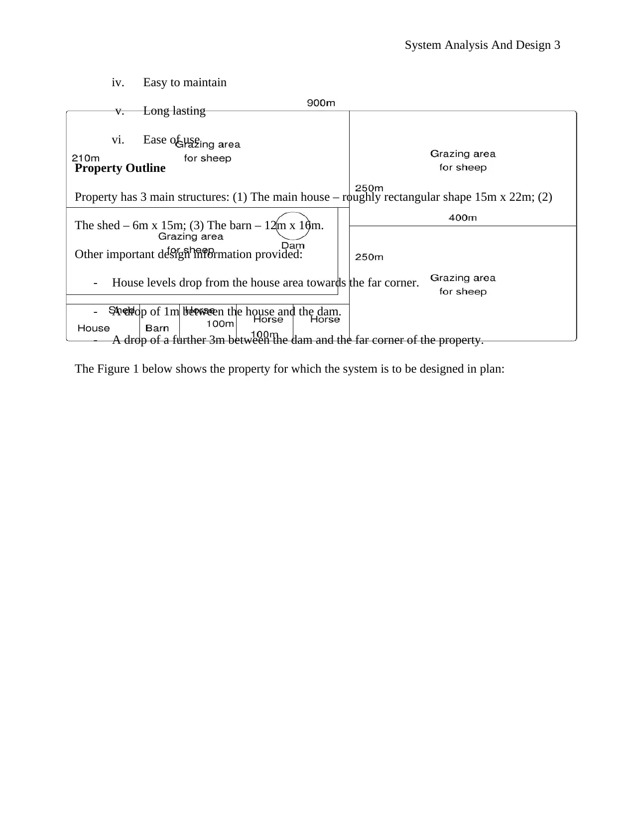
Property Outline
Property has 3 main structures: (1) The main house – roughly rectangular shape 15m x 22m; (2)
The shed – 6m x 15m; (3) The barn – 12m x 16m.
Other important design information provided:
- House levels drop from the house area towards the far corner.
- A drop of 1m between the house and the dam.
- A drop of a further 3m between the dam and the far corner of the property.
The Figure 1 below shows the property for which the system is to be designed in plan:
iv. Easy to maintain
v. Long lasting
vi. Ease of use
Property Outline
Property has 3 main structures: (1) The main house – roughly rectangular shape 15m x 22m; (2)
The shed – 6m x 15m; (3) The barn – 12m x 16m.
Other important design information provided:
- House levels drop from the house area towards the far corner.
- A drop of 1m between the house and the dam.
- A drop of a further 3m between the dam and the far corner of the property.
The Figure 1 below shows the property for which the system is to be designed in plan:
⊘ This is a preview!⊘
Do you want full access?
Subscribe today to unlock all pages.
Trusted by 1+ million students worldwide
System Analysis And Design 4
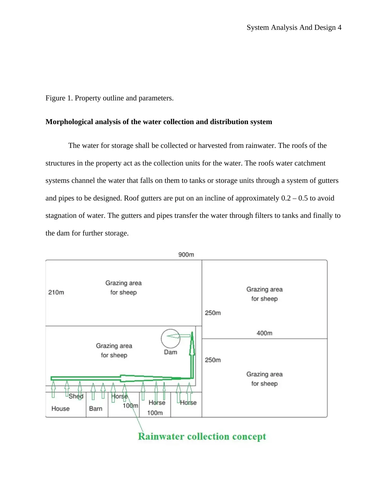
Figure 1. Property outline and parameters.
Morphological analysis of the water collection and distribution system
The water for storage shall be collected or harvested from rainwater. The roofs of the
structures in the property act as the collection units for the water. The roofs water catchment
systems channel the water that falls on them to tanks or storage units through a system of gutters
and pipes to be designed. Roof gutters are put on an incline of approximately 0.2 – 0.5 to avoid
stagnation of water. The gutters and pipes transfer the water through filters to tanks and finally to
the dam for further storage.
Paraphrase This Document
Need a fresh take? Get an instant paraphrase of this document with our AI Paraphraser
System Analysis And Design 5
Preliminary Design
System Configuration
Roof Areas:
Main house = 15m x 22m
= 330m2
Shed = 6m x 15m
= 90m2
Barn = 12m x 16m
= 192m2
Total roof area for water collection = 330m2 + 90m2 + 192m2
= 612m2
After finding the roof area, the next step is to design the gutters and pipes to be used to
collect water from the roofs. This is done using CORE 9 or excels applications, whichever is
appropriate. The detailed designed are contained in the project files.
Sizing gutters to convey water:
The flow within the gutters was modeled. In this design system, the water flow is
considered to be spatially flowing. The roof slope given for the structures is 1. Using the
parameters given for the design, the gutters to be used for the roof system to optimally drain at a
slope of 1 are chosen from design tables.
System Analysis And Design 6
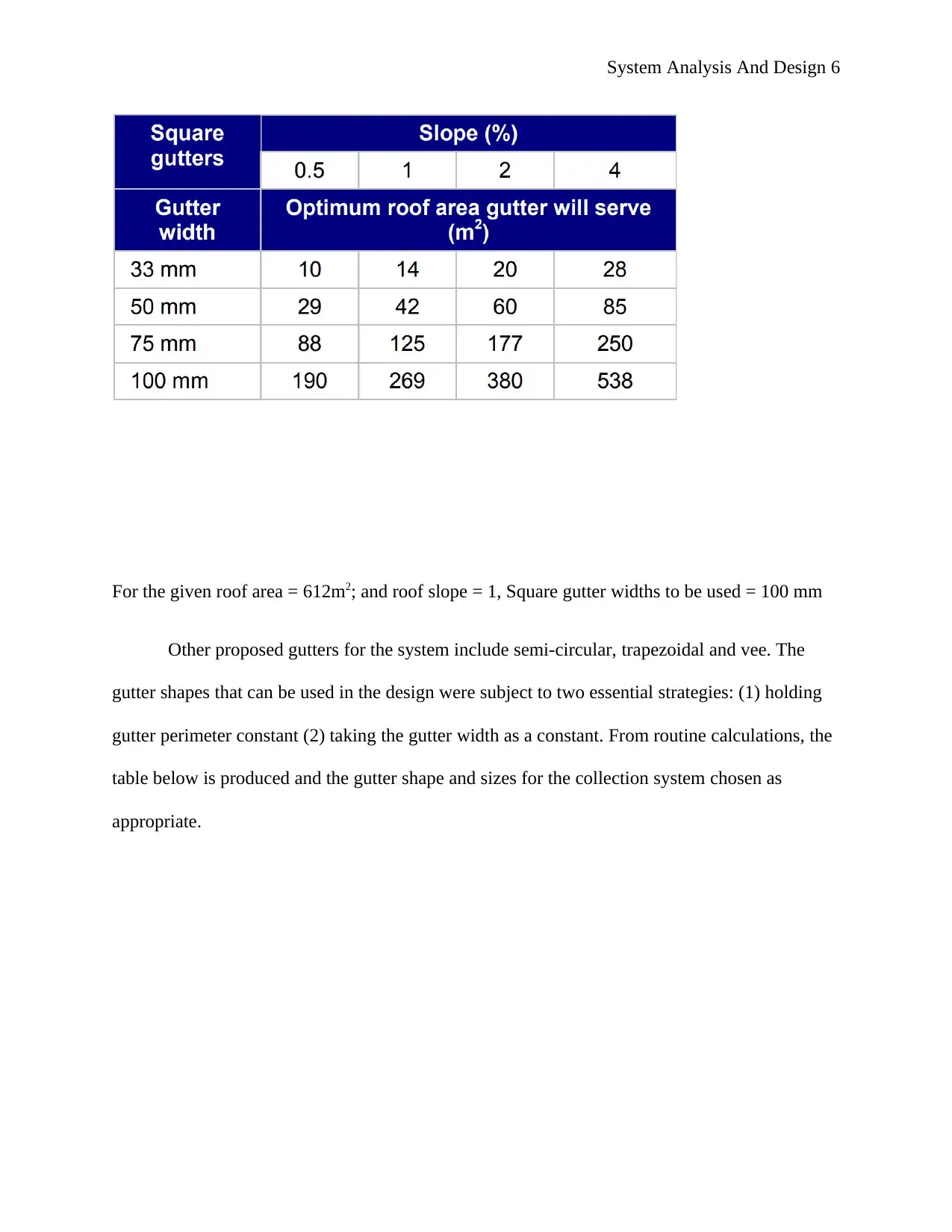
For the given roof area = 612m2; and roof slope = 1, Square gutter widths to be used = 100 mm
Other proposed gutters for the system include semi-circular, trapezoidal and vee. The
gutter shapes that can be used in the design were subject to two essential strategies: (1) holding
gutter perimeter constant (2) taking the gutter width as a constant. From routine calculations, the
table below is produced and the gutter shape and sizes for the collection system chosen as
appropriate.
⊘ This is a preview!⊘
Do you want full access?
Subscribe today to unlock all pages.
Trusted by 1+ million students worldwide
System Analysis And Design 7
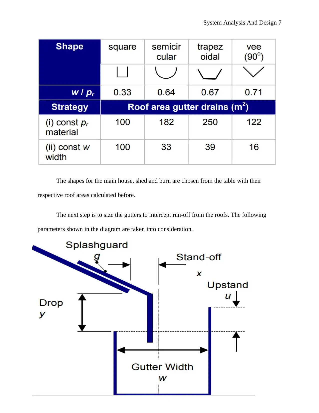
The shapes for the main house, shed and burn are chosen from the table with their
respective roof areas calculated before.
The next step is to size the gutters to intercept run-off from the roofs. The following
parameters shown in the diagram are taken into consideration.
The shapes for the main house, shed and burn are chosen from the table with their
respective roof areas calculated before.
The next step is to size the gutters to intercept run-off from the roofs. The following
parameters shown in the diagram are taken into consideration.
Paraphrase This Document
Need a fresh take? Get an instant paraphrase of this document with our AI Paraphraser
System Analysis And Design 8
The drainage system must have downpipes to transfer the water from the gutters to the
storage facility (the dam). The number and size of downpipes used are designed based on the
roof area collecting the water, the rainfall intensity of the locality, and the amount of the
expected runoff from the roofs.
Downpipe designs:
Rainfall intensity/quantity – The assumptions made in this system are the property is
located in a locality with a rainfall intensity of between 0.03 (l/s)/m2 and 1.8 (l/min)/m2. The
water collection and distribution system of the property is based on the intensities
aforementioned herein and thus the system is expected not to overflow. The amount of water on
the roof surface from the rainfall depends on the effective roof surface area in m2 and this is
multiplied by the rain intensity.
The rainwater downpipes size and number are determinable from design calculations.
The gutters are also chosen from the design thereof.
Rainfall on the property structures roofs will be given by the formulas:
Qh = ( α x i ) x ( ß x F ) formula 1
Qh = the rainwater load in litres/minute (l/min.)
Where; α = the reduction factor for the rain intensity for flat roofs
i = rain intensity and is 1.8 (litre / minute)/ m²
ß = reduction factor for the roof width is determined by the pitch of the roof
F = surface of the roof
F, roof surface is determined by multiplying length (l) and width (b) of the roof.

System Analysis And Design 9
The table below shows the reduction factors used to determine the rainwater load to
downpipes for a maximum rainfall intensity of 1.8 (l/min)/m2.
Downpipe determination
The number of downpipes and their respective sizes are determined from gutter and
downpipe design tables - table 5.13 (AS/NZS 3500.3.2).
The last design involves designing onsite drainage storage – the dam. UPRCT method is
used for the design of the OSD system. The detailed design contains all the parameters input and
output to CORE 9 to give an ideal dam for water storage for the property.
Detailed Design
Roof catchments – there are five main roof catchments in the property.
⊘ This is a preview!⊘
Do you want full access?
Subscribe today to unlock all pages.
Trusted by 1+ million students worldwide
System Analysis And Design 10
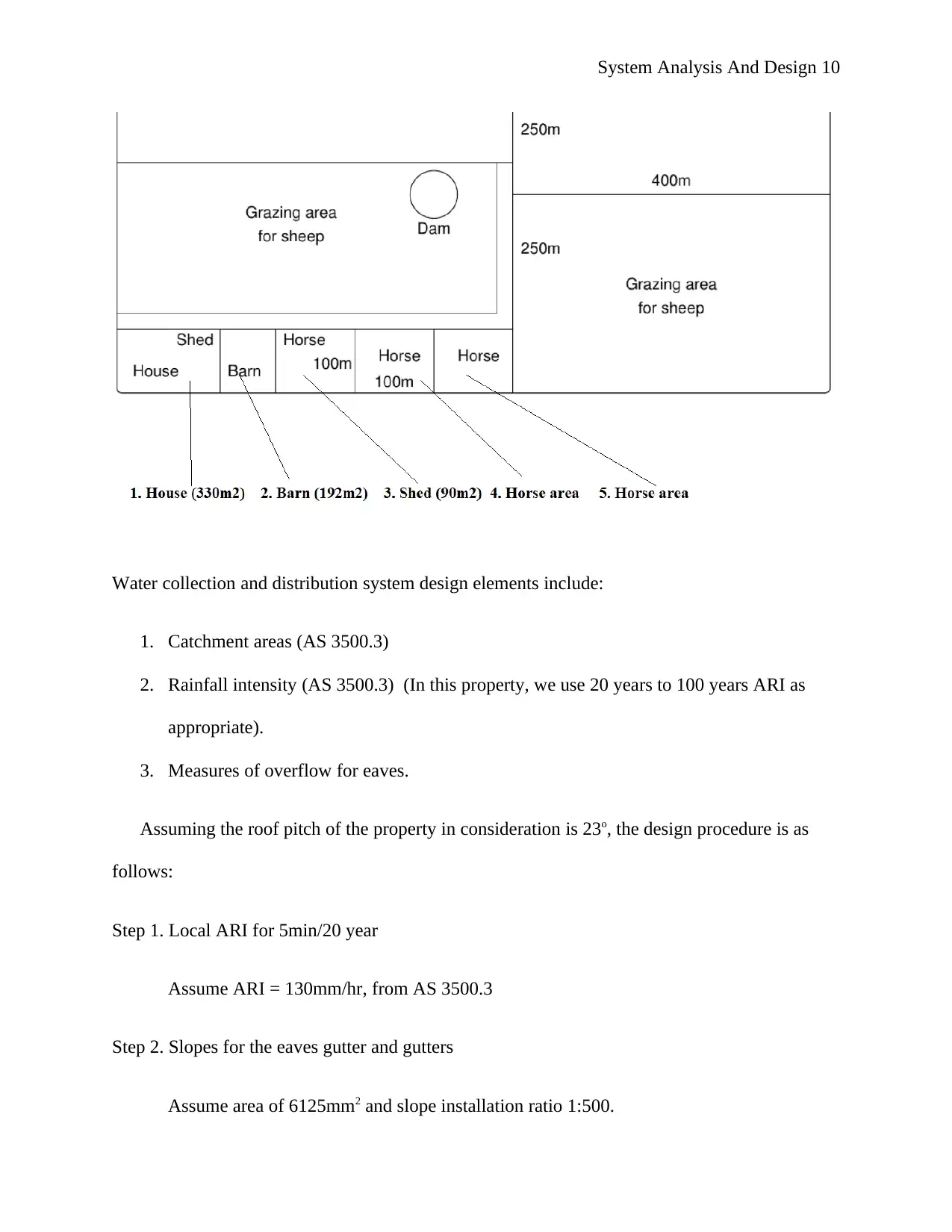
Water collection and distribution system design elements include:
1. Catchment areas (AS 3500.3)
2. Rainfall intensity (AS 3500.3) (In this property, we use 20 years to 100 years ARI as
appropriate).
3. Measures of overflow for eaves.
Assuming the roof pitch of the property in consideration is 23o, the design procedure is as
follows:
Step 1. Local ARI for 5min/20 year
Assume ARI = 130mm/hr, from AS 3500.3
Step 2. Slopes for the eaves gutter and gutters
Assume area of 6125mm2 and slope installation ratio 1:500.
Paraphrase This Document
Need a fresh take? Get an instant paraphrase of this document with our AI Paraphraser
System Analysis And Design 11
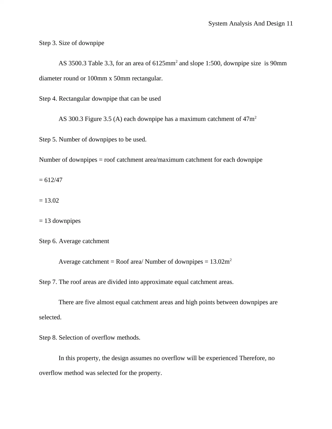
Step 3. Size of downpipe
AS 3500.3 Table 3.3, for an area of 6125mm2 and slope 1:500, downpipe size is 90mm
diameter round or 100mm x 50mm rectangular.
Step 4. Rectangular downpipe that can be used
AS 300.3 Figure 3.5 (A) each downpipe has a maximum catchment of 47m2
Step 5. Number of downpipes to be used.
Number of downpipes = roof catchment area/maximum catchment for each downpipe
= 612/47
= 13.02
= 13 downpipes
Step 6. Average catchment
Average catchment = Roof area/ Number of downpipes = 13.02m2
Step 7. The roof areas are divided into approximate equal catchment areas.
There are five almost equal catchment areas and high points between downpipes are
selected.
Step 8. Selection of overflow methods.
In this property, the design assumes no overflow will be experienced Therefore, no
overflow method was selected for the property.
System Analysis And Design 12
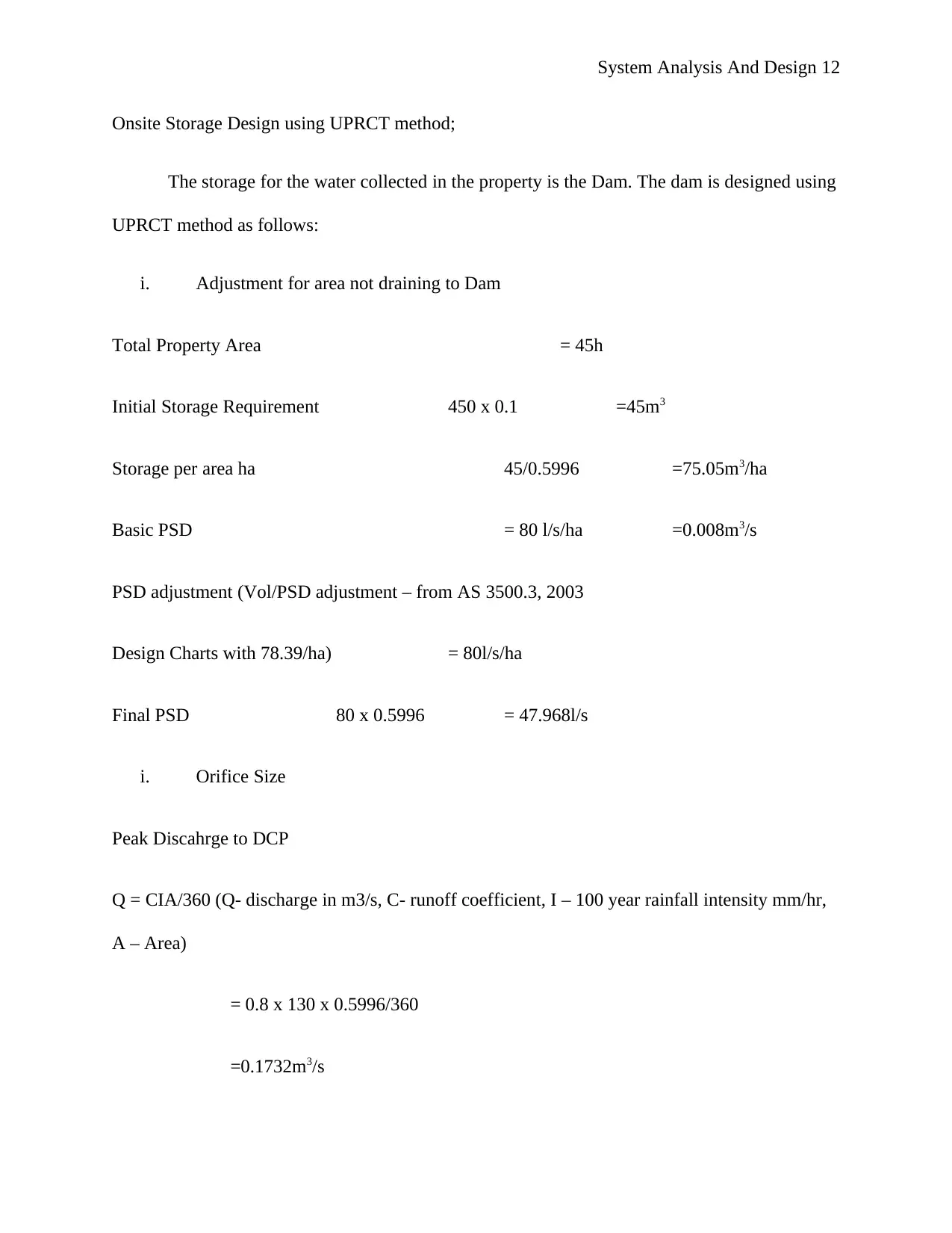
Onsite Storage Design using UPRCT method;
The storage for the water collected in the property is the Dam. The dam is designed using
UPRCT method as follows:
i. Adjustment for area not draining to Dam
Total Property Area = 45h
Initial Storage Requirement 450 x 0.1 =45m3
Storage per area ha 45/0.5996 =75.05m3/ha
Basic PSD = 80 l/s/ha =0.008m3/s
PSD adjustment (Vol/PSD adjustment – from AS 3500.3, 2003
Design Charts with 78.39/ha) = 80l/s/ha
Final PSD 80 x 0.5996 = 47.968l/s
i. Orifice Size
Peak Discahrge to DCP
Q = CIA/360 (Q- discharge in m3/s, C- runoff coefficient, I – 100 year rainfall intensity mm/hr,
A – Area)
= 0.8 x 130 x 0.5996/360
=0.1732m3/s
⊘ This is a preview!⊘
Do you want full access?
Subscribe today to unlock all pages.
Trusted by 1+ million students worldwide
1 out of 18
Your All-in-One AI-Powered Toolkit for Academic Success.
+13062052269
info@desklib.com
Available 24*7 on WhatsApp / Email
![[object Object]](/_next/static/media/star-bottom.7253800d.svg)
Unlock your academic potential
Copyright © 2020–2025 A2Z Services. All Rights Reserved. Developed and managed by ZUCOL.