Water Level Indicator Project: Circuit Design and Analysis
VerifiedAdded on 2023/06/05
|6
|604
|436
Project
AI Summary
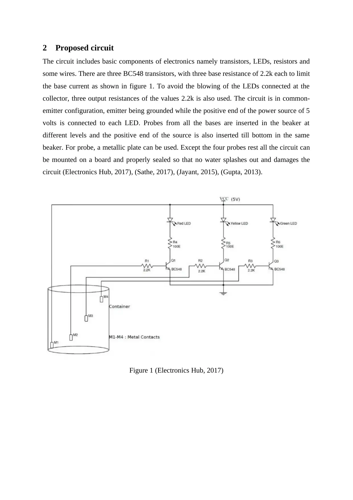
This project report details the design and implementation of a water level indicator circuit using transistors. The circuit utilizes three BC548 transistors, LEDs, and resistors to indicate different water levels. The system employs probes placed at various heights within a container to detect water levels, wit...

Water Level Indicator using
Transistors
<Author name>
<Guide name>
<Month name yyyy>
Dissertation submitted in partial fulfillment for the degree
of
<Degree name> in <insert your degree title>
<Faculty name>
<University name>
Transistors
<Author name>
<Guide name>
<Month name yyyy>
Dissertation submitted in partial fulfillment for the degree
of
<Degree name> in <insert your degree title>
<Faculty name>
<University name>
Paraphrase This Document
Need a fresh take? Get an instant paraphrase of this document with our AI Paraphraser

1 Introduction
1.1 Objectives
A water level indicator helps to notify about the threshold level of water whenever reached. It
uses three LEDs of different colors to act as an indicator for different water levels.
1.2 Significance
The three colors chosen are red, yellow and green. A water level alarm can be used to avoid
water wastage. It uses basic electronic components that helps to increase the conceptual
knowledge.

2 Proposed circuit
The circuit includes basic components of electronics namely transistors, LEDs, resistors and
some wires. There are three BC548 transistors, with three base resistance of 2.2k each to limit
the base current as shown in figure 1. To avoid the blowing of the LEDs connected at the
collector, three output resistances of the values 2.2k is also used. The circuit is in common-
emitter configuration, emitter being grounded while the positive end of the power source of 5
volts is connected to each LED. Probes from all the bases are inserted in the beaker at
different levels and the positive end of the source is also inserted till bottom in the same
beaker. For probe, a metallic plate can be used. Except the four probes rest all the circuit can
be mounted on a board and properly sealed so that no water splashes out and damages the
circuit (Electronics Hub, 2017), (Sathe, 2017), (Jayant, 2015), (Gupta, 2013).
Figure 1 (Electronics Hub, 2017)
⊘ This is a preview!⊘
Do you want full access?
Subscribe today to unlock all pages.

Trusted by 1+ million students worldwide

3 Progress to date
The prototype of this system has been designed successfully. All the LEDs have been tested
properly along with the working of the transistor as desired. All the component is mounted on
a separate board, away from the water source except the probes. The main damage that can be
caused is the physical damage either by water or manual disturbance. Sudden jerks can
loosen the connections. So in the next phase these challenges has to be met and make it better
in terms of robustness. It can be properly sealed so that not even s single drop can enter the
circuit.
Paraphrase This Document
Need a fresh take? Get an instant paraphrase of this document with our AI Paraphraser

4 Conclusion
Transistors are the main components of this system. Transistors acts like a switch when the
base input is controlled. Here, when the water touches any probe and since tap water
conducts electricity, it is shortened to the positive voltage of the source and conducts current
in through the LEDs and it glows. The basic working of the transistors is demonstrated
through this circuit.

5 References
Electronics Hub. (2017, March 14). Simple Water Level Indicator with Alarm (Tested
Circuits). Retrieved from https://www.electronicshub.org:
https://www.electronicshub.org/water-level-alarm-using-555-timer/
Gupta, S. (2013, April 20). How Water Level Indicator Works? Retrieved from
https://www.eeweb.com: https://www.eeweb.com/member-projects/how-water-level-
indicator-works
Jayant. (2015, May 15). Water Level Indicator Alarm. Retrieved from
https://circuitdigest.com: https://circuitdigest.com/electronic-circuits/water-level-
indicator-alarm-circuit
Sathe, V. D. (2017, May 5). Water Level Indicator with Alarm. Retrieved from
https://electronicsforu.com: https://electronicsforu.com/electronics-projects/hardware-
diy/water-level-indicator-alarm
⊘ This is a preview!⊘
Do you want full access?
Subscribe today to unlock all pages.

Trusted by 1+ million students worldwide
1 out of 6

Your All-in-One AI-Powered Toolkit for Academic Success.
+13062052269
info@desklib.com
Available 24*7 on WhatsApp / Email
Unlock your academic potential
© 2024 | Zucol Services PVT LTD | All rights reserved.