Wind Turbine Aerodynamic Theory and Simulation
Added on 2022-10-06
37 Pages10501 Words443 Views
Supervisor: XXXX
This project reports the various things related to wind energy extraction devices are explained.
Especially the report mainly focuses on the different kind of wind turbines and different type of
wind energy extraction methods. And the calculation of various performance parameters for the
different wind turbines is discussed in this report. And a brief overview of the BEM technique is
explained in this report. Insights founded from the literature review is discussed in this report. It
brings an overview of wind energy extraction. Also, the 2D and 3D simulation of wind turbines is
carried out as a part of this research.
College of Engineering, Swansea University, 2019
© Student Name, 2019
WIND TURBINE AERODYNAMIC
THEORY AND SIMULATION
By
Student Name
MSc Aerospace Engineering
Table of Contents
Chapter 1 Introduction.................................................................................................................4
1.1 Background.....................................................................................................................4
1.2 Major parameters used in the wind energy calculation....................................................6
1.3 Objectives........................................................................................................................8
Chapter 2 Literature Review........................................................................................................8
2.1 Horizontal axis wind turbines..........................................................................................8
2.2 Vertical axis wind turbines............................................................................................10
2.3 Wind Energy calculations methodologies......................................................................11
Chapter 3 Methodology.............................................................................................................14
3.1 Method of Blade Element Momentum (BEM)..............................................................14
3.2 Theory of Momentum....................................................................................................14
3.3 Theory for Axial Momentum.........................................................................................14
3.4 Theory of blade element................................................................................................16
Chapter 4 Simulation.................................................................................................................20
4.1 2D CFD.........................................................................................................................20
4.1.1 2D-CFD.................................................................................................................20
4.1.2 Results 2D-CFD....................................................................................................21
4.2 3D CFD.........................................................................................................................25
4.2.1 Annex XX blade....................................................................................................25
4.2.2 Geometric properties of the Annex XX blade........................................................26
4.2.3 3D-CFD Results....................................................................................................27
Chapter 5 Results and Discussions.............................................................................................28
5.1 BEM Results.................................................................................................................28
Chapter 6 Conclusion.................................................................................................................32
References.....................................................................................................................................32
1
List of Figures
Figure 1 VAWT and HAWT...........................................................................................................6
Figure 2 Betz Limit.........................................................................................................................8
Figure 3 Stream tube.....................................................................................................................15
Figure 4 Annular ring division......................................................................................................16
Figure 5 Different angles definition..............................................................................................17
Figure 6 Pressure coefficient.........................................................................................................22
Figure 7 The pressure terms of Cl, the angle of incidence 5 degree..............................................23
Figure 8 The pressure terms of the Cd, the angle of incidence of 5 degree..................................23
Figure 9 The pressure terms of the Cm, the angle of incidence of 5 degree..................................23
Figure 10 The friction terms of the Cl...........................................................................................24
Figure 11 The friction terms convergence of the Cd.....................................................................24
Figure 12 The friction terms convergence of the Cm....................................................................24
Figure 13 The Navier-Stokes equations logarithm of the residual.................................................25
Figure 14 Twist distribution..........................................................................................................26
Figure 15 Chord distribution.........................................................................................................26
Figure 16 The topology top view..................................................................................................26
Figure 17 Topology slice...............................................................................................................27
Figure 18 Grid cells at the blade surface.......................................................................................27
Figure 19 Grid slice.......................................................................................................................27
Figure 20 Upper surface streamlines.............................................................................................28
Figure 21 Comparison of induction factors and Betz limit............................................................29
Figure 22 Induction factor’s convergence at r=1.25 m..................................................................29
Figure 23 Comparison of geometric and inflow angles.................................................................30
Figure 24 Components in thrust and direction of torque and Cl section........................................30
Figure 25 the forces and torque along the radius...........................................................................31
Figure 26 Sectional power coefficient Crow.................................................................................31
2

Chapter 1 Introduction
1.1 Background
The quantity of energy that a turbine can extract from the wind is affected by three main
variables: wind speed, air density, and swept area. In simple words, the function of wind turbines
is opposite to that of a fan. Wind turbines make use of wind to create electricity whereas a fan
uses electricity. The blades are set into motion by the wind and they cause the generator to
produce electricity [3].
The aerodynamic force, generated by the rotor blades, operates a lot like an aero plane
wing or helicopter rotor blade. It is used by wind turbines to convert wind energy to electricity.
The air pressure is reduced on one side of the blade when wind runs through it. Air pressure gap,
between both sides of the blade, produces lift and drag. This aerodynamic force conversion into a
generator's rotation generates electricity [33]. There are two fundamental categories of modern
wind turbines:
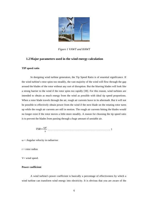
Horizontal-Axis Turbines: Many individuals picture turbines as horizontal-axis wind
turbines (right picture). They are usually made up of three blades and are powered
"upwind," meaning the turbine pivots at the top of the tower to allow the blades to
experience wind.
Upwind turbines - designed to work on upwind conditions. Uses special
arrangements to make the rotor blades against the wind direction.
Downwind turbines - Designed to work on downwind mode. Does not use any
special arrangements like tail vane etc. The blades naturally track the wind.
Shrouded wind turbines - Wind turbine with augmentor is termed as shrouded
wind turbines. Her wind flow rate is increased by the help of augmentor.
Vertical-Axis Turbines: There are many kinds of vertical-axis wind turbines (left
picture). One is the eggbeater-style Darrieus model, labelled upon its French maker.
These turbines are omnidirectional, which means they do not have to be modified to point
into the wind in order to function. Again vertical wind turbines are classified into the
many types. Some of them are discussed here.
Early wind turbine - Oldest windmill design used by Persians in 1000 b.c.
4
1.1 Background
The quantity of energy that a turbine can extract from the wind is affected by three main
variables: wind speed, air density, and swept area. In simple words, the function of wind turbines
is opposite to that of a fan. Wind turbines make use of wind to create electricity whereas a fan
uses electricity. The blades are set into motion by the wind and they cause the generator to
produce electricity [3].
The aerodynamic force, generated by the rotor blades, operates a lot like an aero plane
wing or helicopter rotor blade. It is used by wind turbines to convert wind energy to electricity.
The air pressure is reduced on one side of the blade when wind runs through it. Air pressure gap,
between both sides of the blade, produces lift and drag. This aerodynamic force conversion into a
generator's rotation generates electricity [33]. There are two fundamental categories of modern
wind turbines:
Horizontal-Axis Turbines: Many individuals picture turbines as horizontal-axis wind
turbines (right picture). They are usually made up of three blades and are powered
"upwind," meaning the turbine pivots at the top of the tower to allow the blades to
experience wind.
Upwind turbines - designed to work on upwind conditions. Uses special
arrangements to make the rotor blades against the wind direction.
Downwind turbines - Designed to work on downwind mode. Does not use any
special arrangements like tail vane etc. The blades naturally track the wind.
Shrouded wind turbines - Wind turbine with augmentor is termed as shrouded
wind turbines. Her wind flow rate is increased by the help of augmentor.
Vertical-Axis Turbines: There are many kinds of vertical-axis wind turbines (left
picture). One is the eggbeater-style Darrieus model, labelled upon its French maker.
These turbines are omnidirectional, which means they do not have to be modified to point
into the wind in order to function. Again vertical wind turbines are classified into the
many types. Some of them are discussed here.
Early wind turbine - Oldest windmill design used by Persians in 1000 b.c.
4
Savonious wind turbine - It is a drag type windmill. It generates higher torque
than another type of windmills.
It has S-shaped wind turbines.
Flapping panel wind turbine - It works in all directions.
Darrieus turbine - It looks similar to an egg beater. It has a C shaped rotor blade.
Giromill - Most suitable wind turbine design for turbulent wind conditions.
It is a basis of clean fuel. Wind energy does not contaminate the atmosphere like fossil-
fuel combustion power plants such as coal or natural gas. Wind turbines do not generate acid rain
or greenhouse gasses that cause air pollution. Wind energy is a private energy source. The wind
production of the nation is plentiful: cumulative wind energy capacity in the U.S has risen by an
average of 30 per cent a year over the last 10 years, exceeding the 28 per cent growth pace of
global potential. It is quite feasible [25]. The wind is a type of solar energy. The energy generated
can be utilized to supply power across the grid as long as the sun keeps shining and the wind
keeps blowing.
The wind is the most commonly used free energy source that is renewable as well.
This is mainly because the wind is commercially accepted as a low-cost solution to
energy problems. There is no maintenance overhead and the cost is minimal. It does not
adversely affect the client either. Internationally as well people are more aware of the
benefits of renewable energy so it is important that there are efficient means of using this
energy for the maximum benefit of everyone. Wind power is seen as fulfilling the
electricity demands in the future. The working of wind turbines is an interesting
phenomenon. A layer is made when the air flows over the blades of the turbine. The said
layer passes very close to the surface where the forces are strongest. The layer thickens as
more and more wind passes through the surface of the blades. The Kingdom of Saudia
Arabia realizes the importance of this and has started developing programs that utilize the
wind power efficiently. Due to this, the wind power capaigns have been highly successful
regarding the power grid system integration studies that have been started. Careful
planning could lead to efficient usage and meeting the potential energy needs of a whole
country [34].
5
Figure 1 VAWT and HAWT
1.2 Major parameters used in the wind energy calculation
TIP speed ratio
In designing wind turbine generators, the Tip Speed Ratio is of essential significance. If
the wind turbine's rotor spins too steadily, the vast majority of the wind will flow through the gap
around the blades of the rotor without any sort of disruption. But the blurring blades will look like
a strong barrier to the wind if the rotor spins too rapidly [38]. For this reason, wind turbines are
intended to obtain as much energy from the wind as possible with ideal tip speed proportions.
When a rotor blade travels through the air, rough air currents leave in its aftermath. But it will not
be possible to effectively obtain power from the wind if the next blade on the rotating rotor turns
up while the rough air currents are still in motion. The rough air currents hitting the blades would
no longer exist if the rotor moves a little more steadily. A reason for choosing the tip speed ratio
is to prevent the blades from passing through a huge amount of unstable air.
TSR= ωr
v ....................................................................... 1
ω = Angular velocity in radian/sec
r = rotor radius
V= wind speed.
Power coefficient
A wind turbine's power coefficient is basically a percentage of effectiveness by which a
wind turbine can transform wind energy into electricity. It is obvious that you are aware of the
6
method used to calculate the quantity of electricity produced by a wind turbine and also the total
power stored in a specific area of wind. If you want to calculate the coefficient of power at
specified wind speed, you only have to divide the electricity generated by the total energy stored
in the wind at that particular speed. The function of wind turbines is to obtain energy by
decreasing the speed of wind [1]. If a wind turbine has to be 100% efficient, it would have to be
able to stop 100% of the wind but this can only be possible if the rotor is a strong disk, does not
move and hence produces no kinetic energy. Another possibility is to have a wind turbine, which
has a single rotor blade so that the majority of the wind passing through the swept area by the
turbine blade would not even touch the blade and therefore, the whole of the kinetic energy would
be possessed by the wind.
C p= P
Pwind
....................................................................... 2
C p = Coefficient of power
P = Electricity produced by wind turbine
Pwind = Total Energy available in the wind
Betz Limit
It is known as the Betz Limit because it was found by the German physicist, Albert Betz.
He was the one who realized that it was not possible for any wind turbine to convert more than
59.3% of the wind’s kinetic energy into mechanical energy due to the rotation of a rotor [41]. It is
the abstract maximum coefficient of power for any kind of wind turbine.
P ¿ Cp . 1
2 . ρ . S .θ 1
3
....................................................................... 3
P = Reference Power
ρ = Density
S = Cross-sectional area
θ = Velocity
7
End of preview
Want to access all the pages? Upload your documents or become a member.