Antenna, Fading, and Digital Transmission in Wireless Communication
VerifiedAdded on 2023/06/03
|7
|1339
|321
AI Summary
This text explains the concepts of antenna, fading, and digital transmission in wireless communication. It covers topics such as isotropic antenna, radiation pattern, fading due to atmospheric conditions, and the difference between flat fading and selective fading. It also discusses the advantages of digital transmission over analog transmission and the use of amplitude shift keying and quadrature amplitude modulation in digital data transmission. The text includes solved examples and references for further reading.
Contribute Materials
Your contribution can guide someone’s learning journey. Share your
documents today.
Assessment Questions
January 1
2018
January 1
2018
Secure Best Marks with AI Grader
Need help grading? Try our AI Grader for instant feedback on your assignments.
Answer 5 .1 Antenna is an electromagnetic conductor which collects the electric energy. There are
two types of antenna for receiving and transmission antenna for sending and receiving of signals.
Isotropic antenna transmits the data in all directions like horizontally and vertically or radiates equally
in all directions. The radiation pattern for this case may be represented by the sphere whose centre is
coincides (Meyr, H. et al.,1997).
Answer 5.2 The radiation pattern displays relative signal strength at all angles within a given
plane .This information is available from a radiation pattern (Lai, A. et al.,2007).
Answer 5.3 The term fading may be defined as the rapid fluctuation of signal power over a short
interval of time or distance and as result a constructive or destructive interference at receiver or
collector side. In case of a predetermined environment, the fading can be affected by changes in
atmospheric condition such as rainfall and reflection of buildings etc .
Answer 5 .4 The difference between diffraction and scattering are following as :
Diffraction Scattering
(i) It takes place at the edge(boundary)
of an dense body that is much larger
as compared to the wavelength( λ ¿ of
the radio waves .
(i) It takes place when the medium
through which the wave travels
consists of obstacles with dimensions
that are much smaller as compared to
the wavelength of the propagating
signals.
(ii) Diffraction is due to part of wave
being removed.
(ii) Scattering is effectively bouncing off
something .
Answer 5 .5 The difference between the fast and slow fading are following as :
Fast Fading Slow Fading
i. The Fast fading indicate to changes in
signal strength between a transmitter
(source) and receiver as the distance
between the two changes by a smaller
distance of about λ (Wavelength)/2 .
The Slow fading indicate to changes
signal strength between a
transmitter(source) and receiver as the
distance between the two changes by a
larger distance well in excess of λ
(Wavelength).
ii. In case of Fast fading the channel But in case of Slow fading channel
variations is more fast than baseband
signal variations.
variations is slow than baseband signal
variations.
iii. High droppler spread . Low droppler spread.
Answer 5.6 The difference between Flat fading and selective fading is following as :
Flat fading : Flat fading or nonselective type of fading is that type of fading in which all frequency
components of the received signal fluctuates in the equal or same magnitude .This is known as Flat or
nonselective type of fading (Shiu, D.S et al.,2000).
Selective fading : Selective fading affects unequally the different spectral components of a radio
signal. The word selective fading is usually considerable only relative to the bandwidth of the in
general communications channel and in other way Bandwidth of signal is greater than Bandwidth of
channel. This is known as the selective type of fading (Foschini, G.J. and Gans, M.J.,1998).
Answer 5.7 : The three major advantages of digital transmission on analog transmission are as
follows :
(i) In case of digital transmission the signal is exact and data is more secured .
(ii) Digital transmission provides high maximum transmission rates through medium like
optical fibers.
(iii) In case of digital transmission a varieties of services can afford over one line.
Answer 5.8 : In case of a amplitude shift keying the binary values can represent by two different
amplitudes of the carrier frequencies (f) . There is only one amplitude will be zero or absence and
other at constant amplitude of carrier .This is basically used to transmit the digital data over optical
fibre .
A Cos 2 π ftc can be represented by binary 1 .
Answer 5.9 : QAM may be defined as the Quadrature amplitude modulation and it is a popular
analog signaling method that is used in the ADSL (Asymmetric digital subscriber line). Basically it is
a combination of ASK (Amplitude Shift keying) and PSK (Phase shift keying) . Two AM carriers are
modulated 90 degrees out of phase to each other .
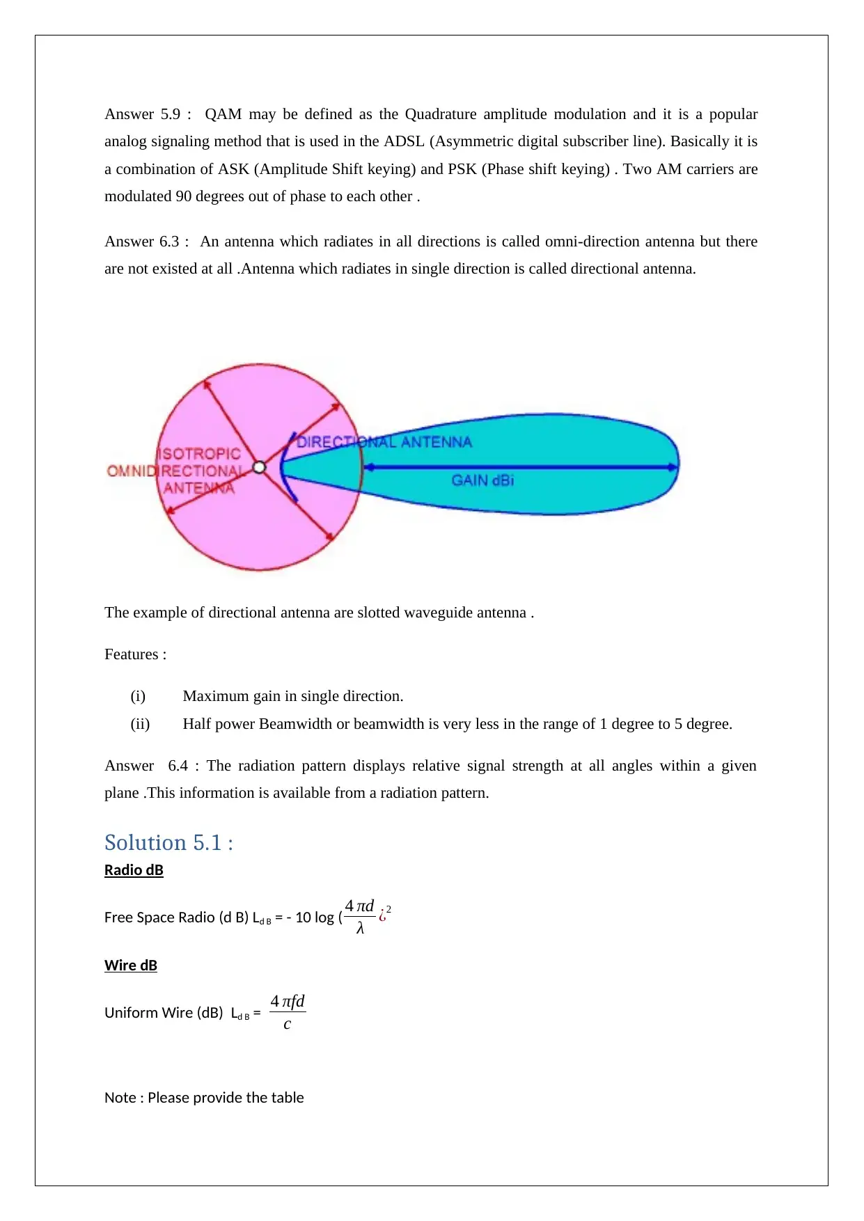
Answer 6.3 : An antenna which radiates in all directions is called omni-direction antenna but there
are not existed at all .Antenna which radiates in single direction is called directional antenna.
The example of directional antenna are slotted waveguide antenna .
Features :
(i) Maximum gain in single direction.
(ii) Half power Beamwidth or beamwidth is very less in the range of 1 degree to 5 degree.
Answer 6.4 : The radiation pattern displays relative signal strength at all angles within a given
plane .This information is available from a radiation pattern.
Solution 5.1 :
Radio dB
Free Space Radio (d B) Ld B = - 10 log ( 4 πd
λ ¿2
Wire dB
Uniform Wire (dB) Ld B = 4 πfd
c
Note : Please provide the table
Secure Best Marks with AI Grader
Need help grading? Try our AI Grader for instant feedback on your assignments.
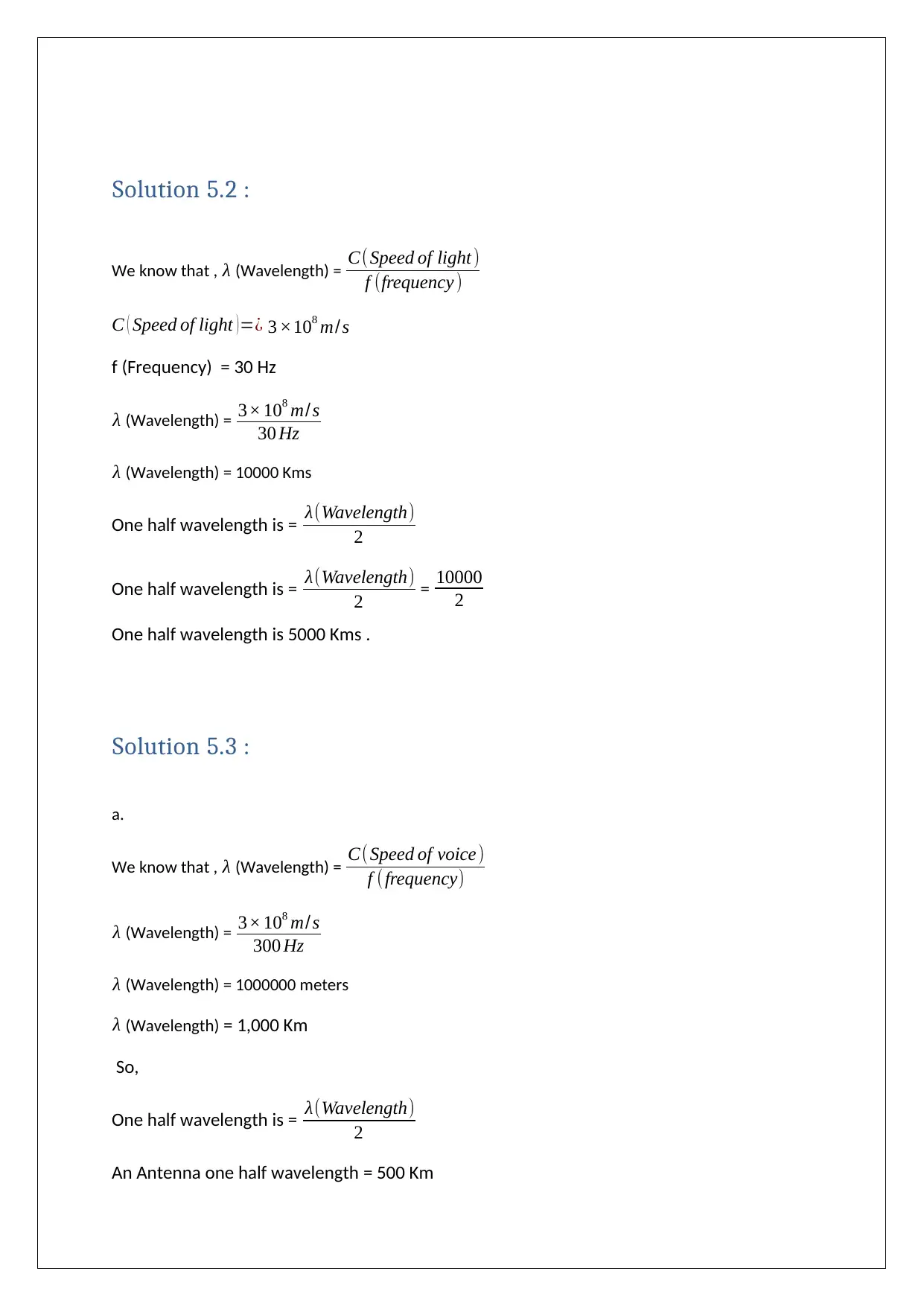
Solution 5.2 :
We know that , λ (Wavelength) = C( Speed of light )
f (frequency )
C ( Speed of light )=¿ 3 ×10⁸ m/s
f (Frequency) = 30 Hz
λ (Wavelength) = 3× 10⁸ m/s
30 Hz
λ (Wavelength) = 10000 Kms
One half wavelength is = λ(Wavelength)
2
One half wavelength is = λ(Wavelength)
2 = 10000
2
One half wavelength is 5000 Kms .
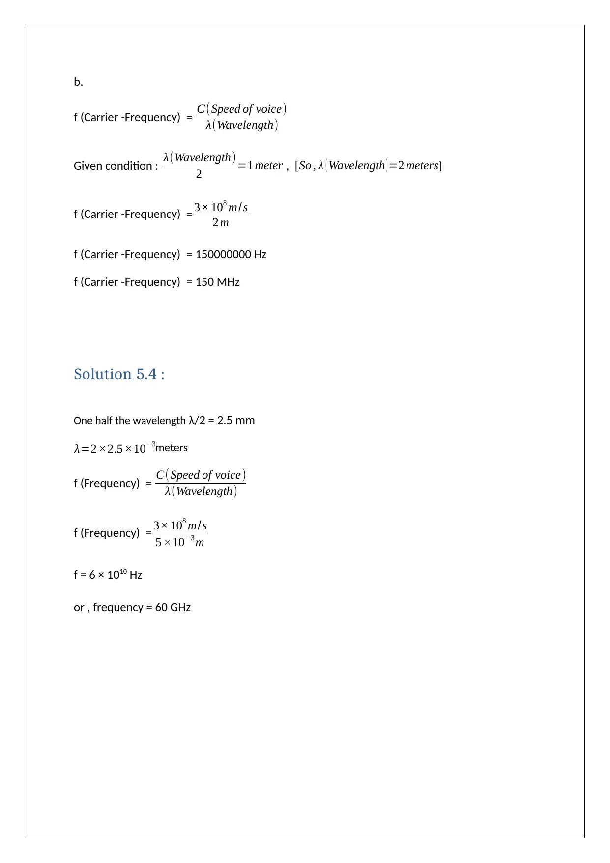
Solution 5.3 :
a.
We know that , λ (Wavelength) = C( Speed of voice)
f ( frequency)
λ (Wavelength) = 3× 10⁸ m/s
300 Hz
λ (Wavelength) = 1000000 meters
λ (Wavelength) = 1,000 Km
So,
One half wavelength is = λ(Wavelength)
2
An Antenna one half wavelength = 500 Km
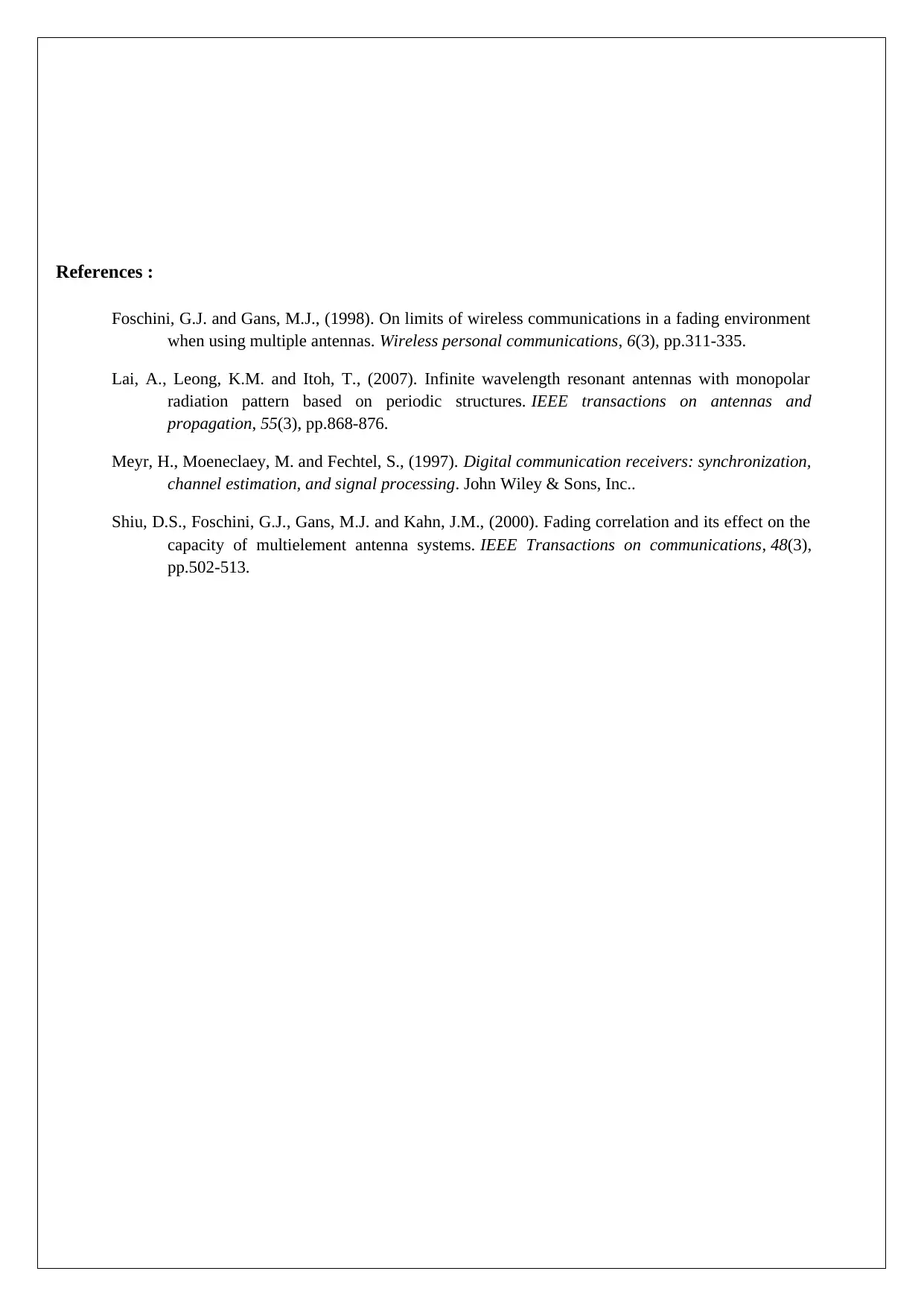
b.
f (Carrier -Frequency) = C(Speed of voice)
λ(Wavelength)
Given condition : λ(Wavelength)
2 =1 meter , [So , λ ( Wavelength )=2 meters]
f (Carrier -Frequency) = 3× 10⁸ m/s
2 m
f (Carrier -Frequency) = 150000000 Hz
f (Carrier -Frequency) = 150 MHz
Solution 5.4 :
One half the wavelength λ/2 = 2.5 mm
λ=2 ×2.5 ×10−3meters
f (Frequency) = C(Speed of voice)
λ(Wavelength)
f (Frequency) = 3× 10⁸ m/s
5 ×10⁻³ m
f = 6 × 10¹⁰ Hz
or , frequency = 60 GHz
References :
Foschini, G.J. and Gans, M.J., (1998). On limits of wireless communications in a fading environment
when using multiple antennas. Wireless personal communications, 6(3), pp.311-335.
Lai, A., Leong, K.M. and Itoh, T., (2007). Infinite wavelength resonant antennas with monopolar
radiation pattern based on periodic structures. IEEE transactions on antennas and
propagation, 55(3), pp.868-876.
Meyr, H., Moeneclaey, M. and Fechtel, S., (1997). Digital communication receivers: synchronization,
channel estimation, and signal processing. John Wiley & Sons, Inc..
Shiu, D.S., Foschini, G.J., Gans, M.J. and Kahn, J.M., (2000). Fading correlation and its effect on the
capacity of multielement antenna systems. IEEE Transactions on communications, 48(3),
pp.502-513.
1 out of 7
Your All-in-One AI-Powered Toolkit for Academic Success.
+13062052269
info@desklib.com
Available 24*7 on WhatsApp / Email
![[object Object]](/_next/static/media/star-bottom.7253800d.svg)
Unlock your academic potential
© 2024 | Zucol Services PVT LTD | All rights reserved.

