MITS5003 Wireless Networks & Communication Assignment, 2019SS
VerifiedAdded on 2022/09/08
|10
|1559
|10
Homework Assignment
AI Summary
This document presents a complete solution to a wireless communications assignment, covering various aspects of wireless networks and communication principles. The assignment delves into the analysis of communication between two hosts, explaining the process through TCP/IP protocols and su...
Running Head: WIRELESS COMMUNICATIONS
0
Wireless Communications
(Student Details: )
12/19/2019
0
Wireless Communications
(Student Details: )
12/19/2019
Paraphrase This Document
Need a fresh take? Get an instant paraphrase of this document with our AI Paraphraser
Wireless Communications
1
Wireless Network and Communication
Answer 1
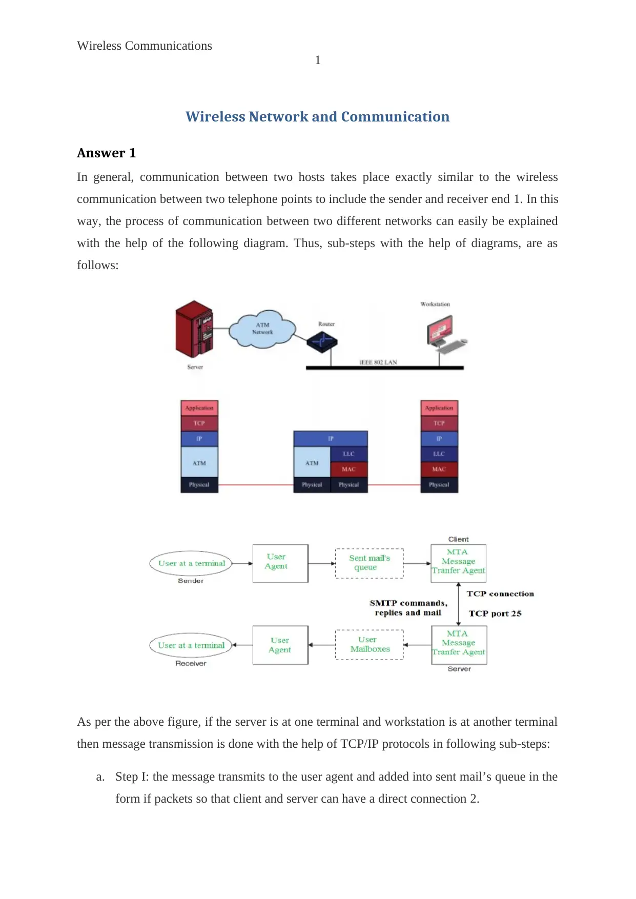
In general, communication between two hosts takes place exactly similar to the wireless
communication between two telephone points to include the sender and receiver end 1. In this
way, the process of communication between two different networks can easily be explained
with the help of the following diagram. Thus, sub-steps with the help of diagrams, are as
follows:
As per the above figure, if the server is at one terminal and workstation is at another terminal
then message transmission is done with the help of TCP/IP protocols in following sub-steps:
a. Step I: the message transmits to the user agent and added into sent mail’s queue in the
form if packets so that client and server can have a direct connection 2.

Wireless Communications
2
b. Step II: with the help of server TCP connection as well as TCP port 25, the message
gets transmitted to the user’s side
c. Step III: as per the TCP/IP layers and protocols, the message is now reaches at user
mailboxes so that user agent receives the message or information which is sent by the
sender
d. Step IV: finally when the packets form a meaningful and non-corrupted message then
it is delivered to the user at the second terminal i.e. receiver via the user agent 3.
Answer 2
Part a
Computed Results are:
a. Maximum Amplitude =8
b. Time period =1/500=0.002 seconds
c. Frequency =500 Hz
d. Phase angle for the wave =0°
Part b
Computed Results are:
a. Maximum Amplitude =3
b. Time period =1/300=0.00333 seconds
c. Frequency =300 Hz
d. Phase angle for the wave =45°
Part c
Computed Results are:
a. Maximum Amplitude =6
b. Time period =1/200=0.005 seconds
c. Frequency =200 Hz
d. Phase angle for the wave =135°
Part d
Computed Results are:
You're viewing a preview
Unlock full access by subscribing today!
Wireless Communications
3
a. Maximum Amplitude =2
b. Time period =1/500=0.002 seconds
c. Frequency =500 Hz
d. Phase angle for the wave =180°
Solution 3
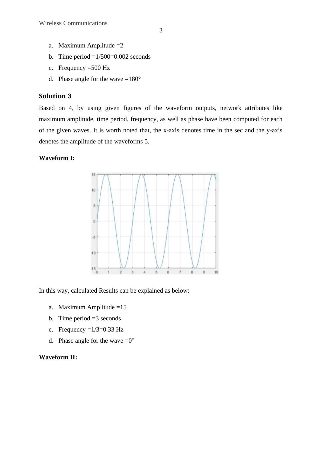
Based on 4, by using given figures of the waveform outputs, network attributes like
maximum amplitude, time period, frequency, as well as phase have been computed for each
of the given waves. It is worth noted that, the x-axis denotes time in the sec and the y-axis
denotes the amplitude of the waveforms 5.
Waveform I:
In this way, calculated Results can be explained as below:
a. Maximum Amplitude =15
b. Time period =3 seconds
c. Frequency =1/3=0.33 Hz
d. Phase angle for the wave =0°
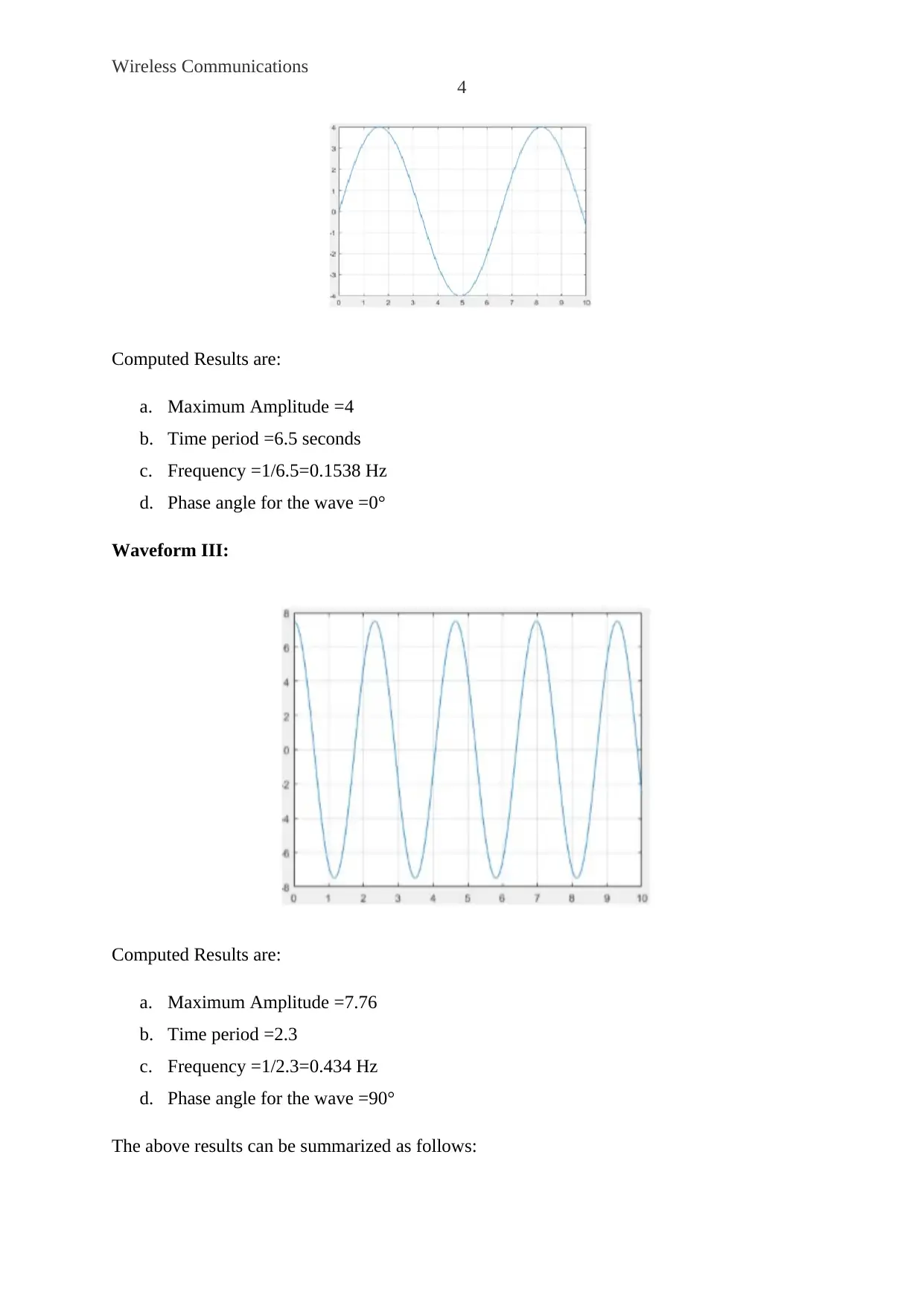
Waveform II:
Paraphrase This Document
Need a fresh take? Get an instant paraphrase of this document with our AI Paraphraser
Wireless Communications
4
Computed Results are:
a. Maximum Amplitude =4
b. Time period =6.5 seconds
c. Frequency =1/6.5=0.1538 Hz
d. Phase angle for the wave =0°
Waveform III:
Computed Results are:
a. Maximum Amplitude =7.76
b. Time period =2.3
c. Frequency =1/2.3=0.434 Hz
d. Phase angle for the wave =90°
The above results can be summarized as follows:

Wireless Communications
5
From the maximum amplitude viewpoint, waveform-I is superior
And from the frequency viewpoint, waveform-III is superior
From the time-period viewpoint, waveform-II is superior
Therefore, the value of phase angle is the same for waveforms I and II, whereas a
phase angle of pi/2 phase has been shown by waveform -III.
Answer 4
The given signal is:
(𝑡) = 5 sin (100𝜋𝑡) + sin (300𝜋𝑡) + sin (600𝜋𝑡)
a. In order to calculate the channel capacity using Nyquist criteria using M= 2, 4, 8,
where M is the number of levels. For given signal,
(𝑡) = 5 sin (100𝜋𝑡) + sin (300𝜋𝑡) + sin (600𝜋𝑡)
The formula is:
Channel Capacity (C) = 2 * Bandwidth * log2 (M)
Now, for the three values of M, there will be three-channel capacities C1, C2, C3.
Channel Capacity (C1) = 2*250* log2 (2)
C1=500 bits per second
Similarly, Channel Capacity (C2) = 2*250* log2 (4)
C2=1000 bits per second
Channel Capacity (C3) = 2*250* log2 (8)
C3=1500 bits per second
b. Fundamental Frequency =GCF of the three frequencies in this system
F1=100𝜋=2𝜋f
F1=50 Hz
F2=1=300𝜋=2𝜋f
F2=150 Hz
F3=600𝜋=2𝜋f
F3=300 Hz
Therefore, F1=50 Hz, F2=150 Hz, and F3=300 Hz.
You're viewing a preview
Unlock full access by subscribing today!

Wireless Communications
6
Now, Fundamental Frequency = 50 Hz
c. In this way, the spectrum needs to be computed and drawn as well, as follows:
-300 -250 -200 -150 -100 -50 0 50 100 150 200 250 300
0
0.5
1
1.5
2
2.5
3
Spectrum
Frequency
Amplitude
d. Bandwidth= maximum frequency-minimum frequency
Bandwidth=300 Hz-50 Hz
Bandwidth=250 Hz
Answer 5
It has been found that Nyquist theorem can easily be used for enhancing the data rate across
the channels 6. It is because the process, with which the data rate over a channel can be
increased, is sub-divided into two major categories:
1. By increasing the bandwidth
2. Without increasing the bandwidth
In this way, data rate can be increased without even increasing the bandwidth of the signal
with the help of Nyquist channel capacity 7. When it requires to be done the following
mentioned formula or mathematical expression is usually used.
Paraphrase This Document
Need a fresh take? Get an instant paraphrase of this document with our AI Paraphraser
Wireless Communications
7
Apart from this, when the data rate is changed without changing the bandwidth of the channel
then there are some disadvantages to this approach. The biggest disadvantage is the poor
reliability. It is because the data rate is increased in this process across one end to another end
with the data rate equation of the bit 8. The second disadvantage of this approach is that the
whole process generates additional sound which is unwanted and unnecessary 4.
Answer 6
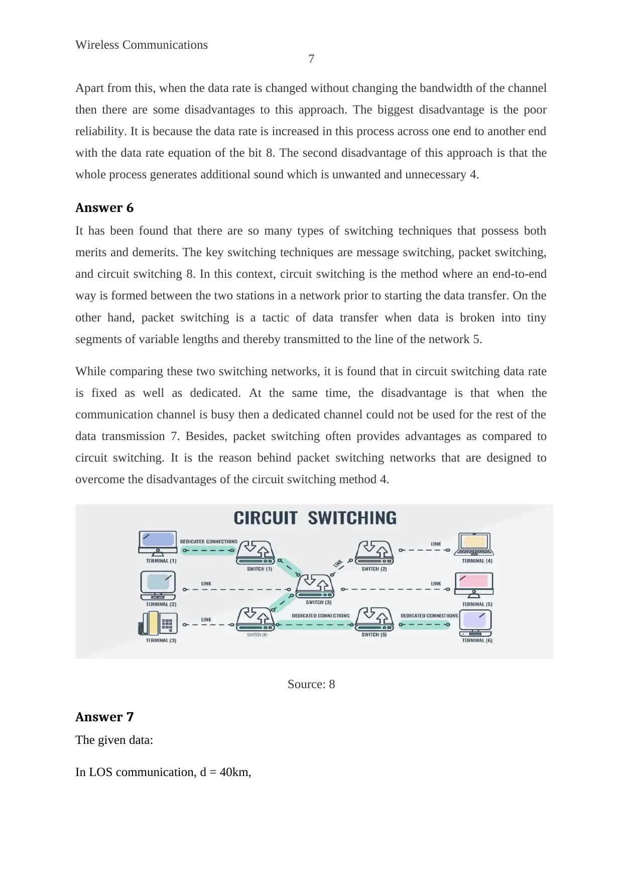
It has been found that there are so many types of switching techniques that possess both
merits and demerits. The key switching techniques are message switching, packet switching,
and circuit switching 8. In this context, circuit switching is the method where an end-to-end
way is formed between the two stations in a network prior to starting the data transfer. On the
other hand, packet switching is a tactic of data transfer when data is broken into tiny
segments of variable lengths and thereby transmitted to the line of the network 5.
While comparing these two switching networks, it is found that in circuit switching data rate
is fixed as well as dedicated. At the same time, the disadvantage is that when the
communication channel is busy then a dedicated channel could not be used for the rest of the
data transmission 7. Besides, packet switching often provides advantages as compared to
circuit switching. It is the reason behind packet switching networks that are designed to
overcome the disadvantages of the circuit switching method 4.
Source: 8
Answer 7
The given data:
In LOS communication, d = 40km,
Wireless Communications
8
The height of one antenna = 3 (The height of the second antenna)
The two antennas given are: transmitter antenna and receiver antenna
As per the given information, H1=3 H2
While considering all of this, the appropriate heights of these two antennas can be calculated
as mentioned in 4:
d = 3.57 sqrt (KH)
The value of K=4/3=1.154
d2= (3.57)2* (KH1 + KH2)
1600=3.57*3.57* 1.1547*(4 H2)
1600=58.866 H2
In this way, the value of H2= 27.180 m
As we know, H1= 3 H2
Therefore, H1=81.541 m
You're viewing a preview
Unlock full access by subscribing today!

Wireless Communications
9
References
x
[1] W. Goralski, The illustrated network: how TCP/IP works in a modern network. London:
Morgan Kaufmann, 2017.
[2] C. Gomez, A. Arcia-Moret, and J. Crowcroft, "TCP in the Internet of Things: from
ostracism to prominence," IEEE internet computing, vol. 22, no. 1, pp. 29-41, 2018.
[3] Y. Shiu, S. Chang, H. Wu, S.\ Huang, and H. Chen, "Physical layer security in wireless
networks: A tutorial," IEEE wireless communications, vol. 18, no. 2, pp. 66-74, 2011.
[4] W. Osterhage, Wireless Network Security. New York: CRC Press, 2018.
[5] C. Beard, W. Stallings, and M. Tahiliani, Wireless communication networks and systems.
UK: Pearson Education Limited, 2016.
[6] S. Khan and A. Pathan, Wireless networks and security. Berlin: Springer, 2013.
[7] L. Godara, Handbook of antennas in wireless communications, 4th ed. London: CRC
Press, 2018.
[8] S. Bi, Y. Zeng, and R. Zhang, "Wireless powered communication networks: An
overview," IEEE Wireless Communications, vol. 23, no. 2, pp. 10-18, 2016.
x
1 out of 10
Related Documents
Your All-in-One AI-Powered Toolkit for Academic Success.
+13062052269
info@desklib.com
Available 24*7 on WhatsApp / Email
![[object Object]](/_next/static/media/star-bottom.7253800d.svg)
Unlock your academic potential
© 2024 | Zucol Services PVT LTD | All rights reserved.


