Wireless Networking Homework: Path Loss and Cellular Architecture
VerifiedAdded on 2022/11/22
|8
|1107
|440
Homework Assignment
AI Summary
This assignment solution covers key concepts in wireless networking. Part A of Task 1 analyzes path loss and received power, deriving formulas and discussing the impact of distance, frequency, and antenna gains. Part B provides GNU Octave code to visualize received power and path loss. Task 2 examines cellular architecture, identifying traffic density in urban, suburban, and rural areas, and explaining the cell splitting method for capacity enhancement. The solution references relevant research papers to support the analysis. The assignment explores the relationship between frequency and wavelength, demonstrating how these parameters affect signal propagation and network design. It also explains the importance of base stations and antenna placement in cellular networks. The provided solution is a comprehensive guide for students studying wireless communication systems.

Wireless Networking
Paraphrase This Document
Need a fresh take? Get an instant paraphrase of this document with our AI Paraphraser
WIRELESS NETWORKING 1
Table of Contents
Task 1..........................................................................................................................................................2
Part A: Path loss and received power......................................................................................................2
Part B: GNU Octave code........................................................................................................................3
Task 2..........................................................................................................................................................5
Question 1...............................................................................................................................................5
Question 2...............................................................................................................................................6
References...................................................................................................................................................7
WIRELESS NETWORKING 2
Task 1
Part A: Path loss and received power
From the provided information it is observed that the Lf(dB) is total free space path loss
between the transmitter and receiver and (d) is the distance between the transmitter antenna and
receiver antenna.
Carrier frequency (fc)= 150, 400 and 1000 MHz
Distance (d)= 0 to 30 km
Pt= 100 watts
Gt= Gr= 0 dB
Now, it is stated that total received power of the transmitted signal can be obtained using
below formula:
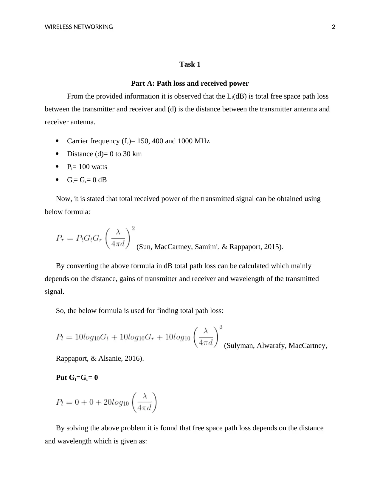
(Sun, MacCartney, Samimi, & Rappaport, 2015).
By converting the above formula in dB total path loss can be calculated which mainly
depends on the distance, gains of transmitter and receiver and wavelength of the transmitted
signal.
So, the below formula is used for finding total path loss:
(Sulyman, Alwarafy, MacCartney,
Rappaport, & Alsanie, 2016).
Put Gt=Gr= 0
By solving the above problem it is found that free space path loss depends on the distance
and wavelength which is given as:
⊘ This is a preview!⊘
Do you want full access?
Subscribe today to unlock all pages.

Trusted by 1+ million students worldwide
WIRELESS NETWORKING 3
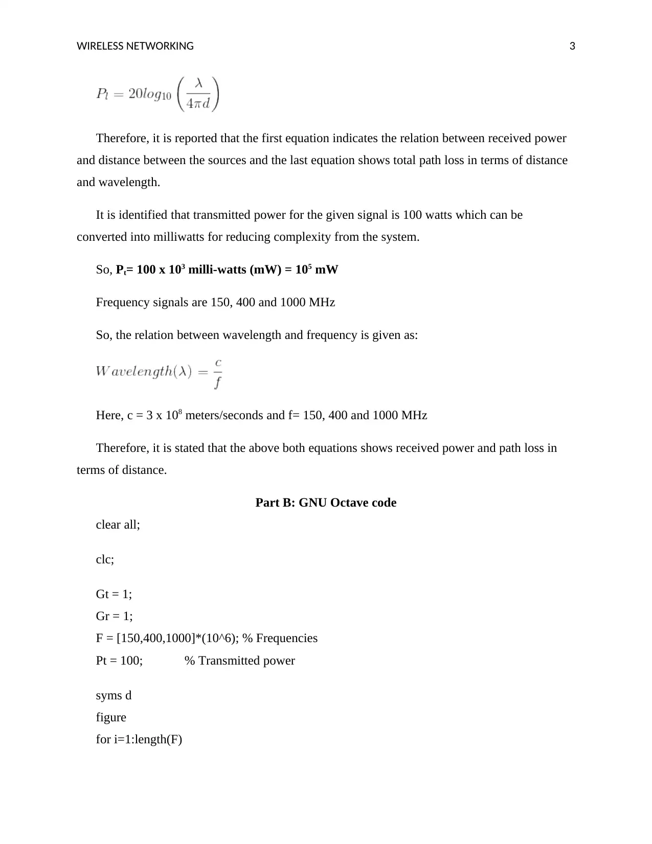
Therefore, it is reported that the first equation indicates the relation between received power
and distance between the sources and the last equation shows total path loss in terms of distance
and wavelength.
It is identified that transmitted power for the given signal is 100 watts which can be
converted into milliwatts for reducing complexity from the system.
So, Pt= 100 x 103 milli-watts (mW) = 105 mW
Frequency signals are 150, 400 and 1000 MHz
So, the relation between wavelength and frequency is given as:
Here, c = 3 x 10⁸ meters/seconds and f= 150, 400 and 1000 MHz
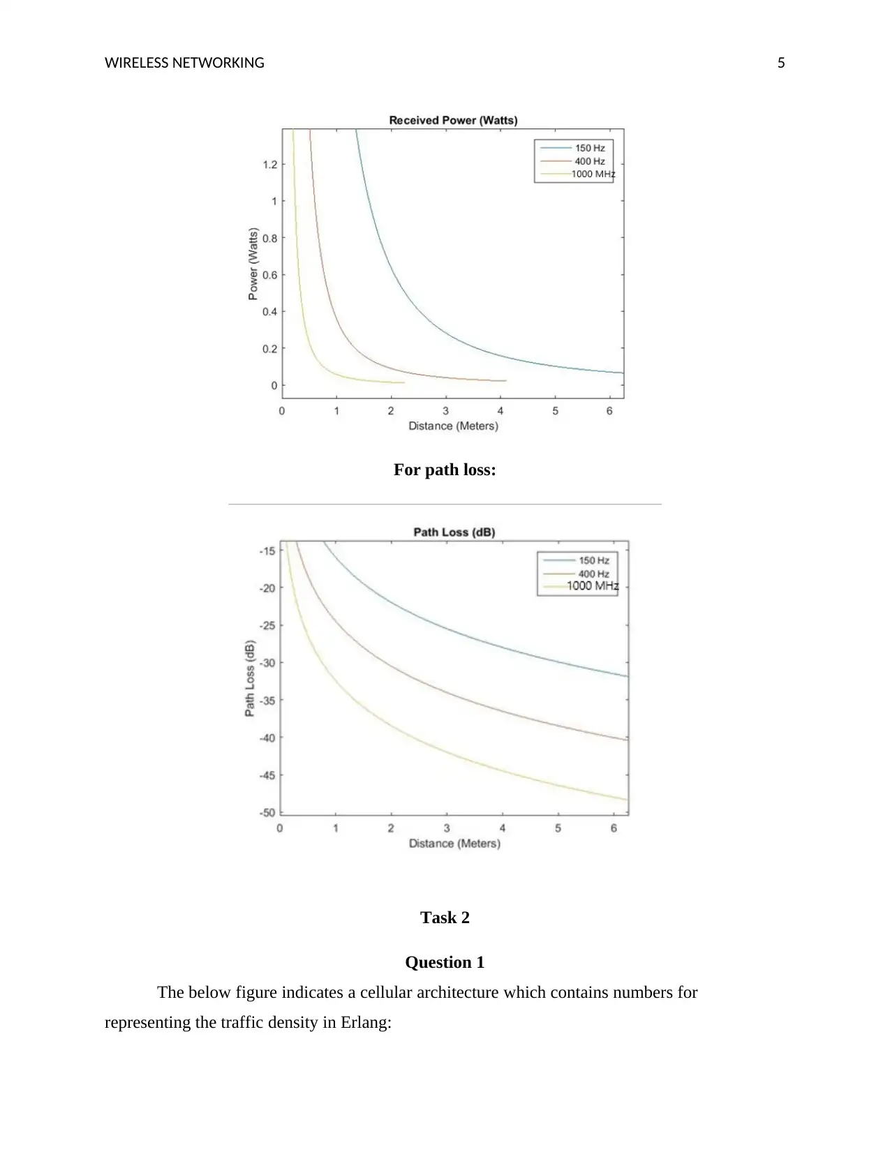
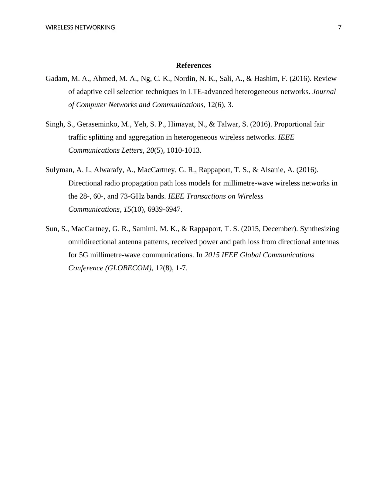
Therefore, it is stated that the above both equations shows received power and path loss in
terms of distance.
Part B: GNU Octave code
clear all;
clc;
Gt = 1;
Gr = 1;
F = [150,400,1000]*(10^6); % Frequencies
Pt = 100; % Transmitted power
syms d
figure
for i=1:length(F)
Paraphrase This Document
Need a fresh take? Get an instant paraphrase of this document with our AI Paraphraser
WIRELESS NETWORKING 4
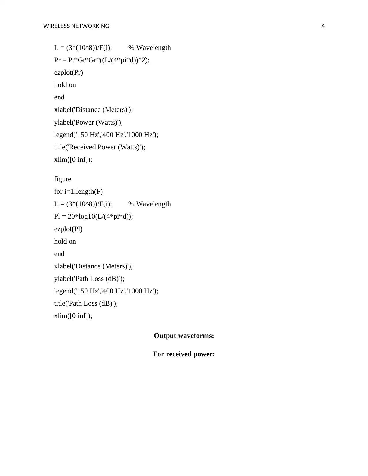
L = (3*(10^8))/F(i); % Wavelength
Pr = Pt*Gt*Gr*((L/(4*pi*d))^2);
ezplot(Pr)
hold on
end
xlabel('Distance (Meters)');
ylabel('Power (Watts)');
legend('150 Hz','400 Hz','1000 Hz');
title('Received Power (Watts)');
xlim([0 inf]);
figure
for i=1:length(F)
L = (3*(10^8))/F(i); % Wavelength
Pl = 20*log10(L/(4*pi*d));
ezplot(Pl)
hold on
end
xlabel('Distance (Meters)');
ylabel('Path Loss (dB)');
legend('150 Hz','400 Hz','1000 Hz');
title('Path Loss (dB)');
xlim([0 inf]);
Output waveforms:
For received power:
L = (3*(10^8))/F(i); % Wavelength
Pr = Pt*Gt*Gr*((L/(4*pi*d))^2);
ezplot(Pr)
hold on
end
xlabel('Distance (Meters)');
ylabel('Power (Watts)');
legend('150 Hz','400 Hz','1000 Hz');
title('Received Power (Watts)');
xlim([0 inf]);
figure
for i=1:length(F)
L = (3*(10^8))/F(i); % Wavelength
Pl = 20*log10(L/(4*pi*d));
ezplot(Pl)
hold on
end
xlabel('Distance (Meters)');
ylabel('Path Loss (dB)');
legend('150 Hz','400 Hz','1000 Hz');
title('Path Loss (dB)');
xlim([0 inf]);
Output waveforms:
For received power:
WIRELESS NETWORKING 5
For path loss:
Task 2
Question 1
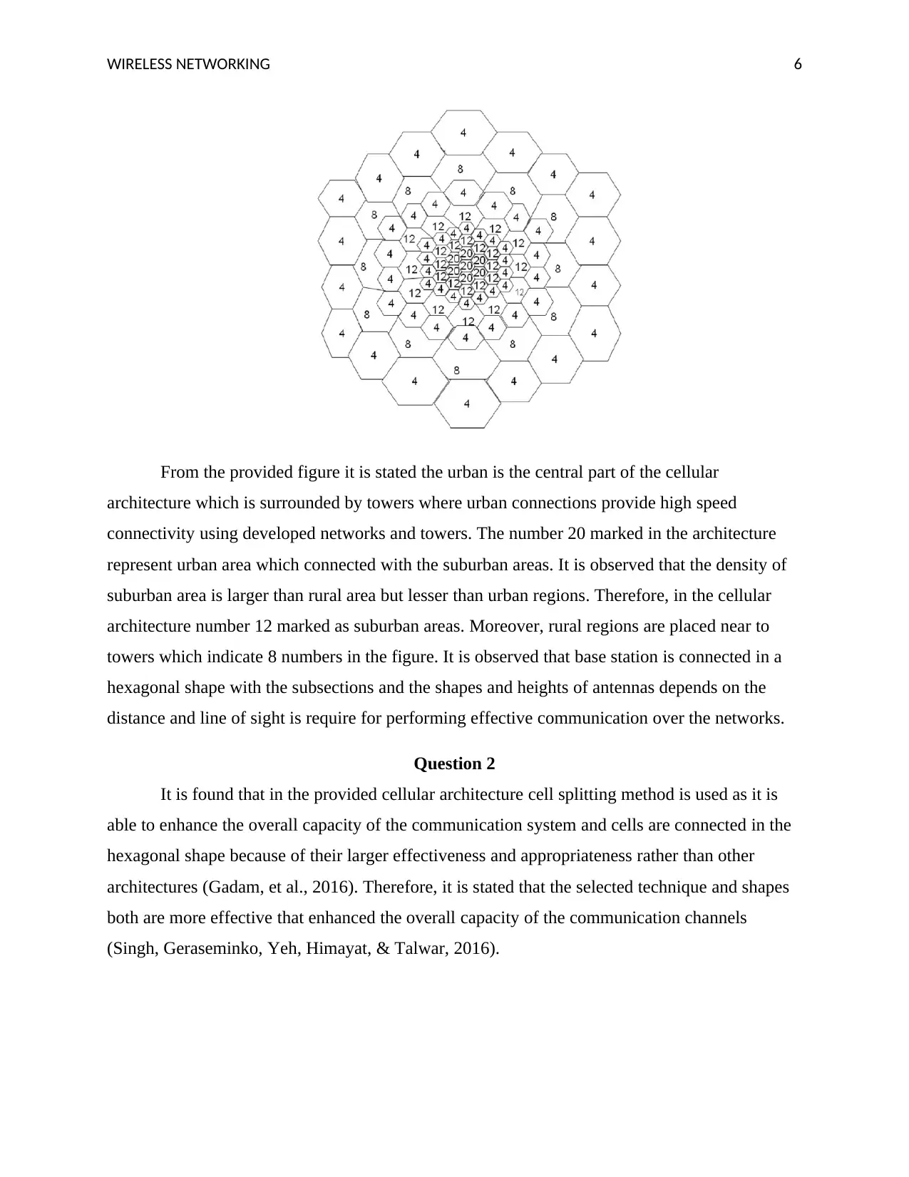
The below figure indicates a cellular architecture which contains numbers for
representing the traffic density in Erlang:
For path loss:
Task 2
Question 1
The below figure indicates a cellular architecture which contains numbers for
representing the traffic density in Erlang:
⊘ This is a preview!⊘
Do you want full access?
Subscribe today to unlock all pages.

Trusted by 1+ million students worldwide
WIRELESS NETWORKING 6
From the provided figure it is stated the urban is the central part of the cellular
architecture which is surrounded by towers where urban connections provide high speed
connectivity using developed networks and towers. The number 20 marked in the architecture
represent urban area which connected with the suburban areas. It is observed that the density of
suburban area is larger than rural area but lesser than urban regions. Therefore, in the cellular
architecture number 12 marked as suburban areas. Moreover, rural regions are placed near to
towers which indicate 8 numbers in the figure. It is observed that base station is connected in a
hexagonal shape with the subsections and the shapes and heights of antennas depends on the
distance and line of sight is require for performing effective communication over the networks.
Question 2
It is found that in the provided cellular architecture cell splitting method is used as it is
able to enhance the overall capacity of the communication system and cells are connected in the
hexagonal shape because of their larger effectiveness and appropriateness rather than other
architectures (Gadam, et al., 2016). Therefore, it is stated that the selected technique and shapes
both are more effective that enhanced the overall capacity of the communication channels
(Singh, Geraseminko, Yeh, Himayat, & Talwar, 2016).
Paraphrase This Document
Need a fresh take? Get an instant paraphrase of this document with our AI Paraphraser
WIRELESS NETWORKING 7
References
Gadam, M. A., Ahmed, M. A., Ng, C. K., Nordin, N. K., Sali, A., & Hashim, F. (2016). Review
of adaptive cell selection techniques in LTE-advanced heterogeneous networks. Journal
of Computer Networks and Communications, 12(6), 3.
Singh, S., Geraseminko, M., Yeh, S. P., Himayat, N., & Talwar, S. (2016). Proportional fair
traffic splitting and aggregation in heterogeneous wireless networks. IEEE
Communications Letters, 20(5), 1010-1013.
Sulyman, A. I., Alwarafy, A., MacCartney, G. R., Rappaport, T. S., & Alsanie, A. (2016).
Directional radio propagation path loss models for millimetre-wave wireless networks in
the 28-, 60-, and 73-GHz bands. IEEE Transactions on Wireless
Communications, 15(10), 6939-6947.
Sun, S., MacCartney, G. R., Samimi, M. K., & Rappaport, T. S. (2015, December). Synthesizing
omnidirectional antenna patterns, received power and path loss from directional antennas
for 5G millimetre-wave communications. In 2015 IEEE Global Communications
Conference (GLOBECOM), 12(8), 1-7.
1 out of 8
Related Documents
Your All-in-One AI-Powered Toolkit for Academic Success.
+13062052269
info@desklib.com
Available 24*7 on WhatsApp / Email
![[object Object]](/_next/static/media/star-bottom.7253800d.svg)
Unlock your academic potential
Copyright © 2020–2026 A2Z Services. All Rights Reserved. Developed and managed by ZUCOL.


