This document provides information about wireless sensor networks, including suitable frequency bands, channel capacity calculations, noise levels, and more. It also discusses the functionalities of cloud applications and the implementation of WSN using IoT platforms.
Contribute Materials
Your contribution can guide someone’s learning journey. Share your
documents today.
Running Head:WIRELESS SENSOR NETWORKS1 Wireless Sensor Networks Name Institution
Secure Best Marks with AI Grader
Need help grading? Try our AI Grader for instant feedback on your assignments.
Wireless Sensor Networks2 In WSN applications, the quality of the Radio Frequency channel is vital. The noise fading measurements are estimated through learning or probe-based methods. The result is high overhead. (a) Select a suitable frequency band for WSN and give reasons for your selection. Many protocols can be used creating a wireless network. 802.15.4 was built for Wirelesses LAN. The network requirements include coverage of 9Km2 area containing 2500 animals to be connected through wireless sensor tags. Each animal will be connected through point-to-point WSN nodes that can transmit up to 250 Kbps. With GB of data per minute, the WSN will use a frequency band of 2.4 GHz band built on 802.15.4 protocol having the 5HGHZ channel. (b)Calculate the channel capacity (minimum data rate) required for: The important considerations in data communication are the speed at which data is transmitted. Data transmission is affected by the following: ï‚·The available bandwidth, the available levels of digital and the quality of the channel. There are two methods used in calculating the data rate. ï‚·BitRate = 2* Bandwidth * Log2 (L) ï‚·The equation shows that the data rate is proportional to the number of signal levels. ï‚·L is the number of signal levels used in data representation. I. One sensing device to control centre channel For this network the data rate would be calculated as follows:
Wireless Sensor Networks3 Bitrate = 2* 2400* log2(2) = 6000bps. Capacity is therefore calculated as follows: Capacity = bandwidth * log2(1 + Signal to Noise Ratio) Signal to noise ratio is given as 10 * log 10 (S/N) and is expressed in decibels. The S/R ratio for this channel is given as 63DB. Therefore, the capacity is finally calculated as follows: C= 2400Hz * log2 (1+ 63) = 24000* 5.97727992. C=143454.71 bps. This the control centre channel capacity. Channel capacity for one sensing device = 143454.71/2500 =57.3bps. II. Control center to ISP channel Using the Shanon’s equation of calculating the channel capacity: C= W log2(1 +SNR) C= 2400Hz * log2 (1+ 63) = 24000* 5.97727992. C=143454.71 bps. (c)For both the channel types calculate the following noise levels experienced: I.Thermal noise
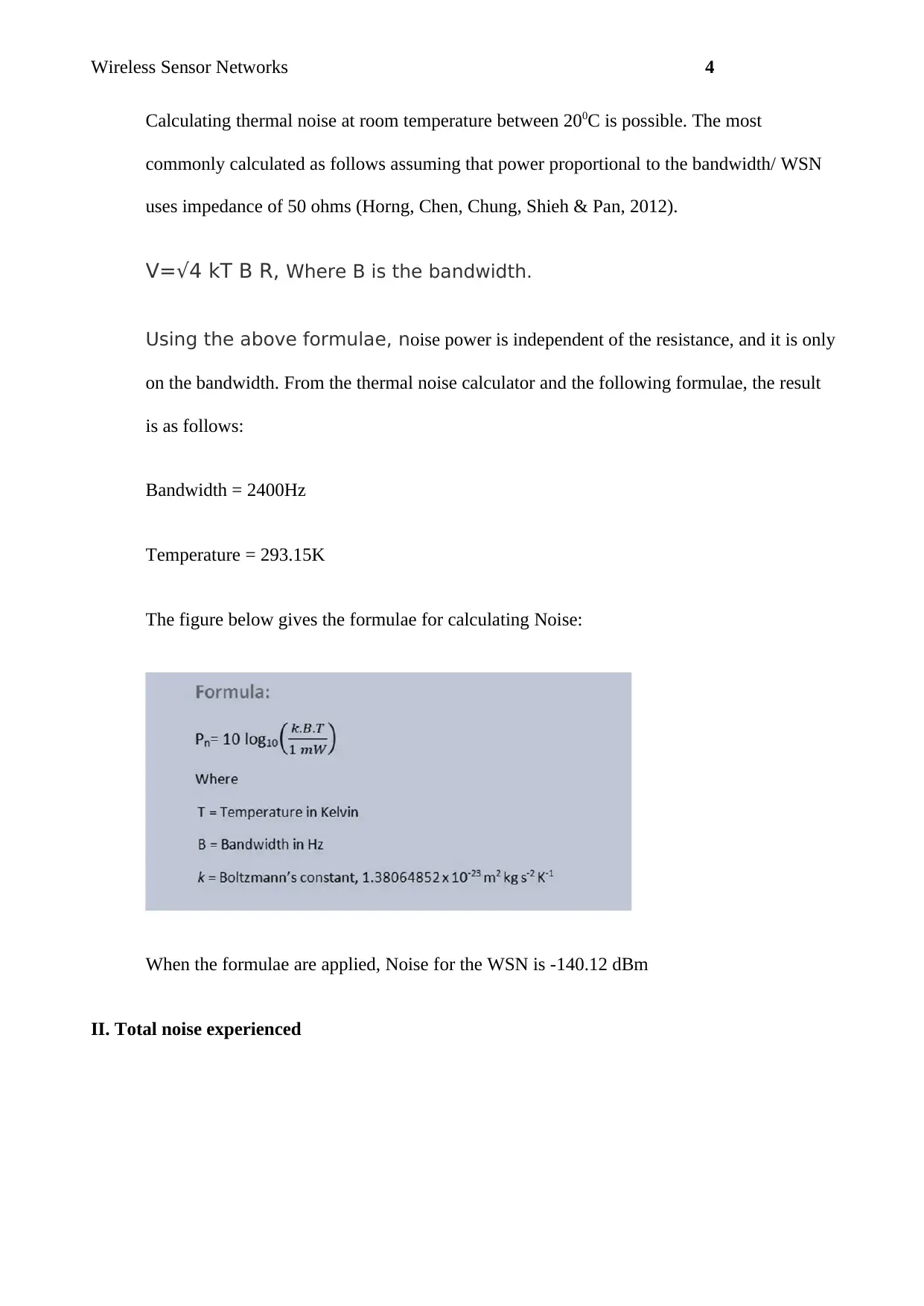
Wireless Sensor Networks4 Calculating thermal noise at room temperature between 200C is possible. The most commonly calculated as follows assuming that power proportional to the bandwidth/ WSN uses impedance of 50 ohms (Horng, Chen, Chung, Shieh & Pan, 2012). V=√4kTBR,Where B is the bandwidth. Using the above formulae, noise power is independent of the resistance, and it is only on the bandwidth. From the thermal noise calculator and the following formulae, the result is as follows: Bandwidth = 2400Hz Temperature = 293.15K The figure below gives the formulae for calculating Noise: When the formulae are applied, Noise for the WSN is -140.12 dBm II. Total noise experienced
Secure Best Marks with AI Grader
Need help grading? Try our AI Grader for instant feedback on your assignments.
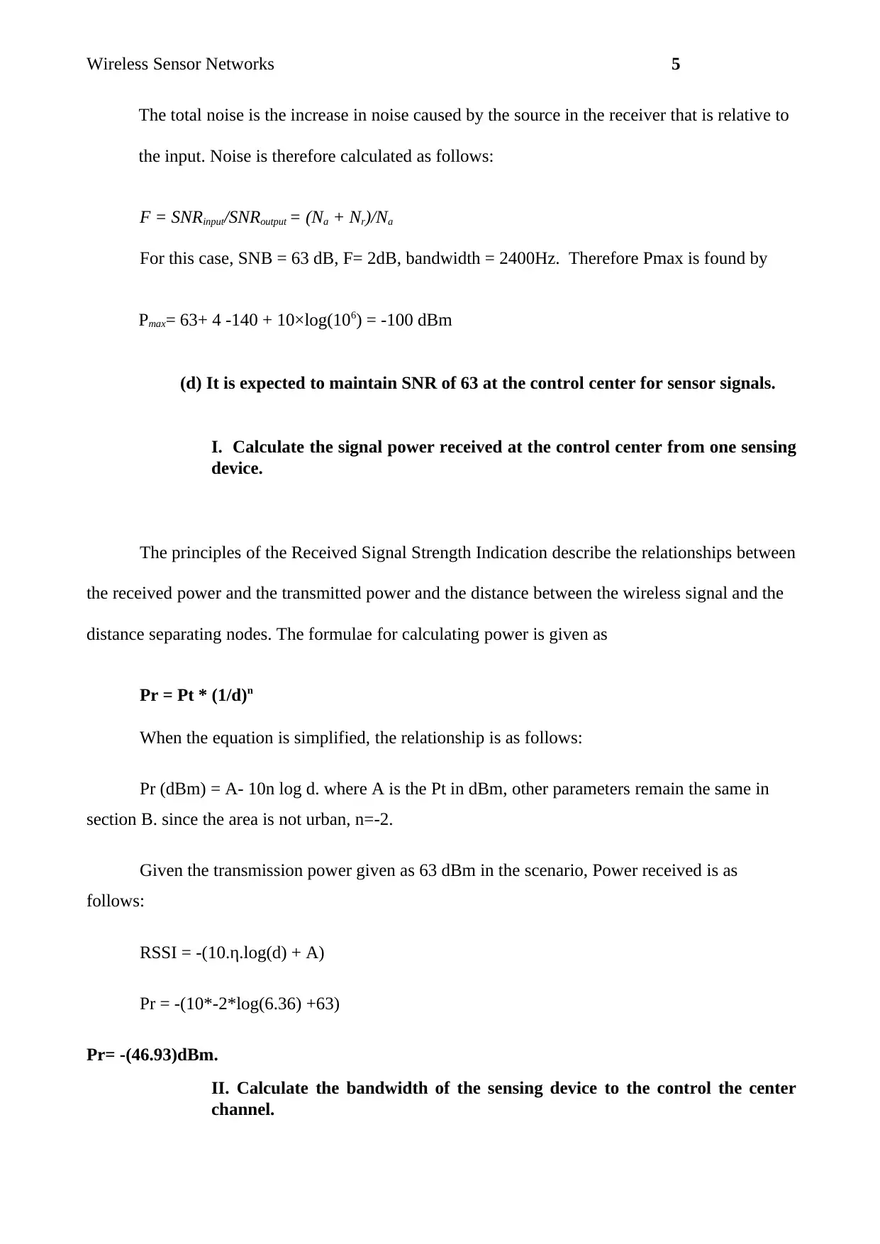
Wireless Sensor Networks5 The total noise is the increase in noise caused by the source in the receiver that is relative to the input. Noise is therefore calculated as follows: F = SNRinput/SNRoutput= (Na+ Nr)/Na For this case, SNB = 63 dB, F= 2dB, bandwidth = 2400Hz. Therefore Pmax is found by Pmax= 63+ 4 -140 + 10×log(106) = -100 dBm (d) It is expected to maintain SNR of 63 at the control center for sensor signals. I. Calculate the signal power received at the control center from one sensing device. The principles of the Received Signal Strength Indication describe the relationships between the received power and the transmitted power and the distance between the wireless signal and the distance separating nodes. The formulae for calculating power is given as Pr = Pt * (1/d)n When the equation is simplified, the relationship is as follows: Pr (dBm) = A- 10n log d. where A is the Pt in dBm, other parameters remain the same in section B. since the area is not urban, n=-2. Given the transmission power given as 63 dBm in the scenario, Power received is as follows: RSSI = -(10.η.log(d) +A) Pr = -(10*-2*log(6.36) +63) Pr= -(46.93)dBm. II. Calculate the bandwidth of the sensing device to the control the center channel.
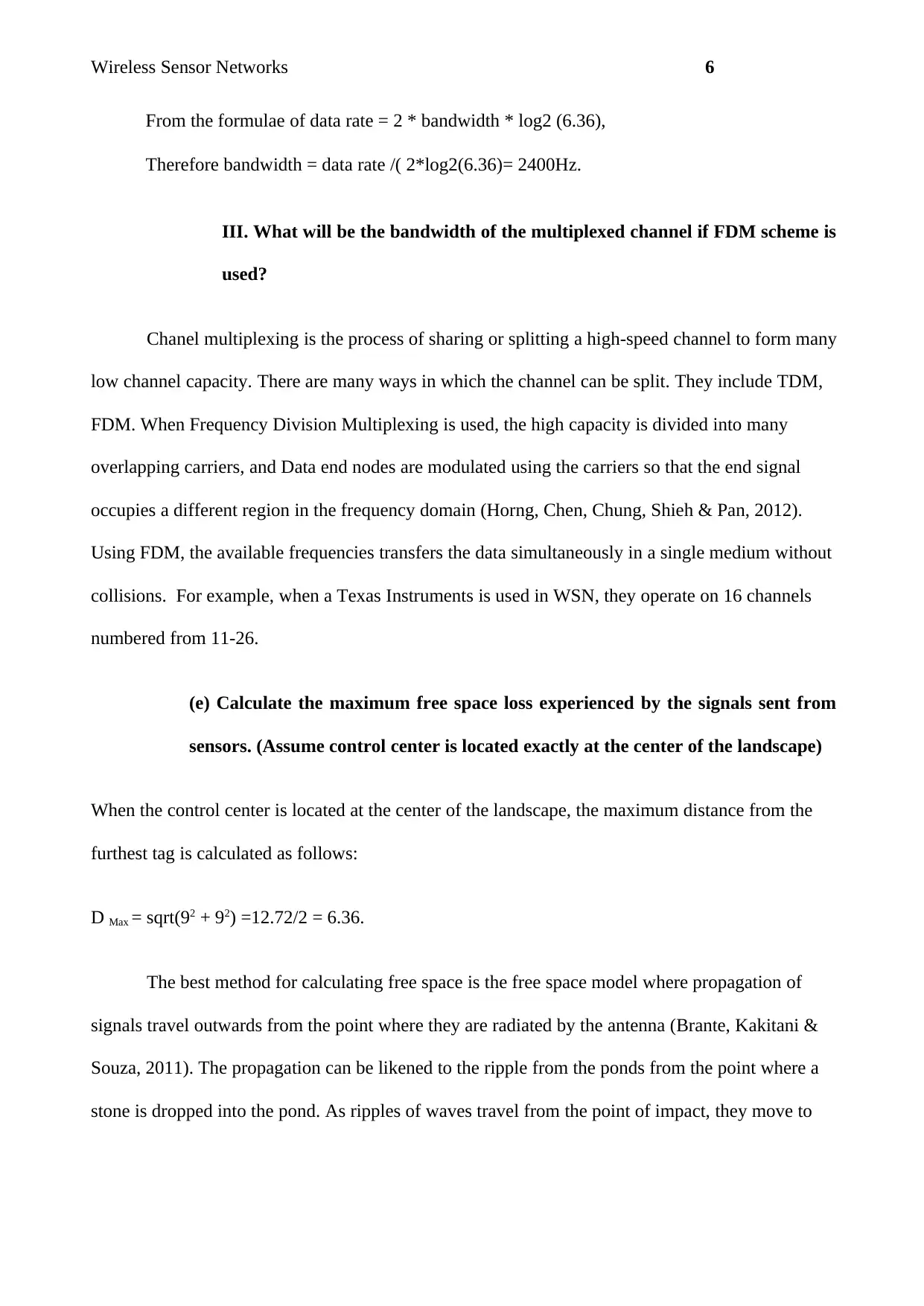
Wireless Sensor Networks6 From the formulae ofdata rate = 2 * bandwidth * log2 (6.36), Therefore bandwidth = data rate /( 2*log2(6.36)= 2400Hz. III. What will be the bandwidth of the multiplexed channel if FDM scheme is used? Chanel multiplexing is the process of sharing or splitting a high-speed channel to form many low channel capacity. There are many ways in which the channel can be split. They include TDM, FDM. When Frequency Division Multiplexing is used, the high capacity is divided into many overlapping carriers, and Data end nodes are modulated using the carriers so that the end signal occupies a different region in the frequency domain (Horng, Chen, Chung, Shieh & Pan, 2012). Using FDM, the available frequencies transfers the data simultaneously in a single medium without collisions. For example, when a Texas Instruments is used in WSN, they operate on 16 channels numbered from 11-26. (e) Calculate the maximum free space loss experienced by the signals sent from sensors. (Assume control center is located exactly at the center of the landscape) When the control center is located at the center of the landscape, the maximum distance from the furthest tag is calculated as follows: DMax= sqrt(92+ 92) =12.72/2 = 6.36. The best method for calculating free space is the free space model where propagation of signals travel outwards from the point where they are radiated by the antenna (Brante, Kakitani & Souza, 2011). The propagation can be likened to the ripple from the ponds from the point where a stone is dropped into the pond. As ripples of waves travel from the point of impact, they move to
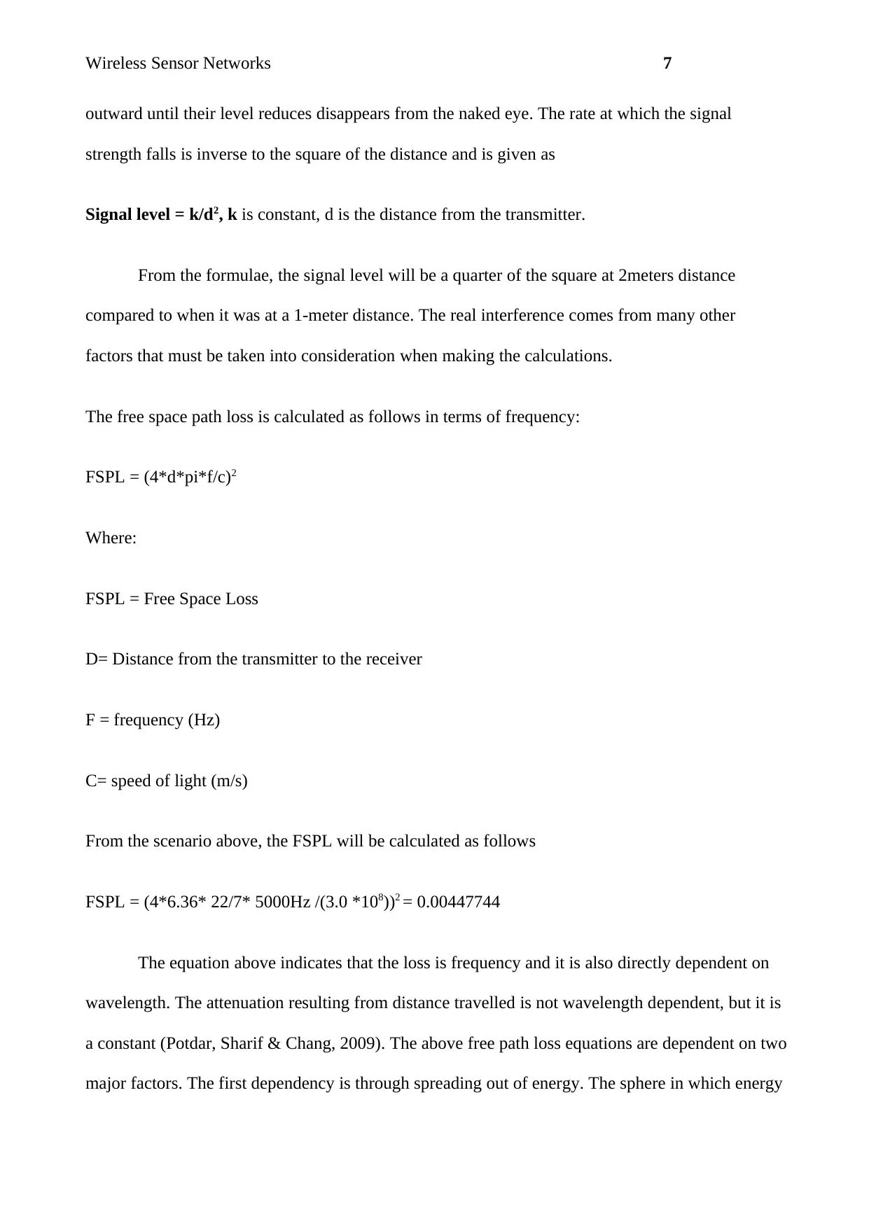
Wireless Sensor Networks7 outward until their level reduces disappears from the naked eye. The rate at which the signal strength falls is inverse to the square of the distance and is given as Signal level = k/d2, kis constant, d is the distance from the transmitter. From the formulae, the signal level will be a quarter of the square at 2meters distance compared to when it was at a 1-meter distance. The real interference comes from many other factors that must be taken into consideration when making the calculations. The free space path loss is calculated as follows in terms of frequency: FSPL = (4*d*pi*f/c)2 Where: FSPL = Free Space Loss D= Distance from the transmitter to the receiver F = frequency (Hz) C= speed of light (m/s) From the scenario above, the FSPL will be calculated as follows FSPL = (4*6.36* 22/7* 5000Hz /(3.0 *108))2=0.00447744 The equation above indicates that the loss is frequency and it is also directly dependent on wavelength. The attenuation resulting from distance travelled is not wavelength dependent, but it is a constant (Potdar, Sharif & Chang, 2009).The above free path loss equations are dependent on two major factors. The first dependency is through spreading out of energy. The sphere in which energy
Paraphrase This Document
Need a fresh take? Get an instant paraphrase of this document with our AI Paraphraser
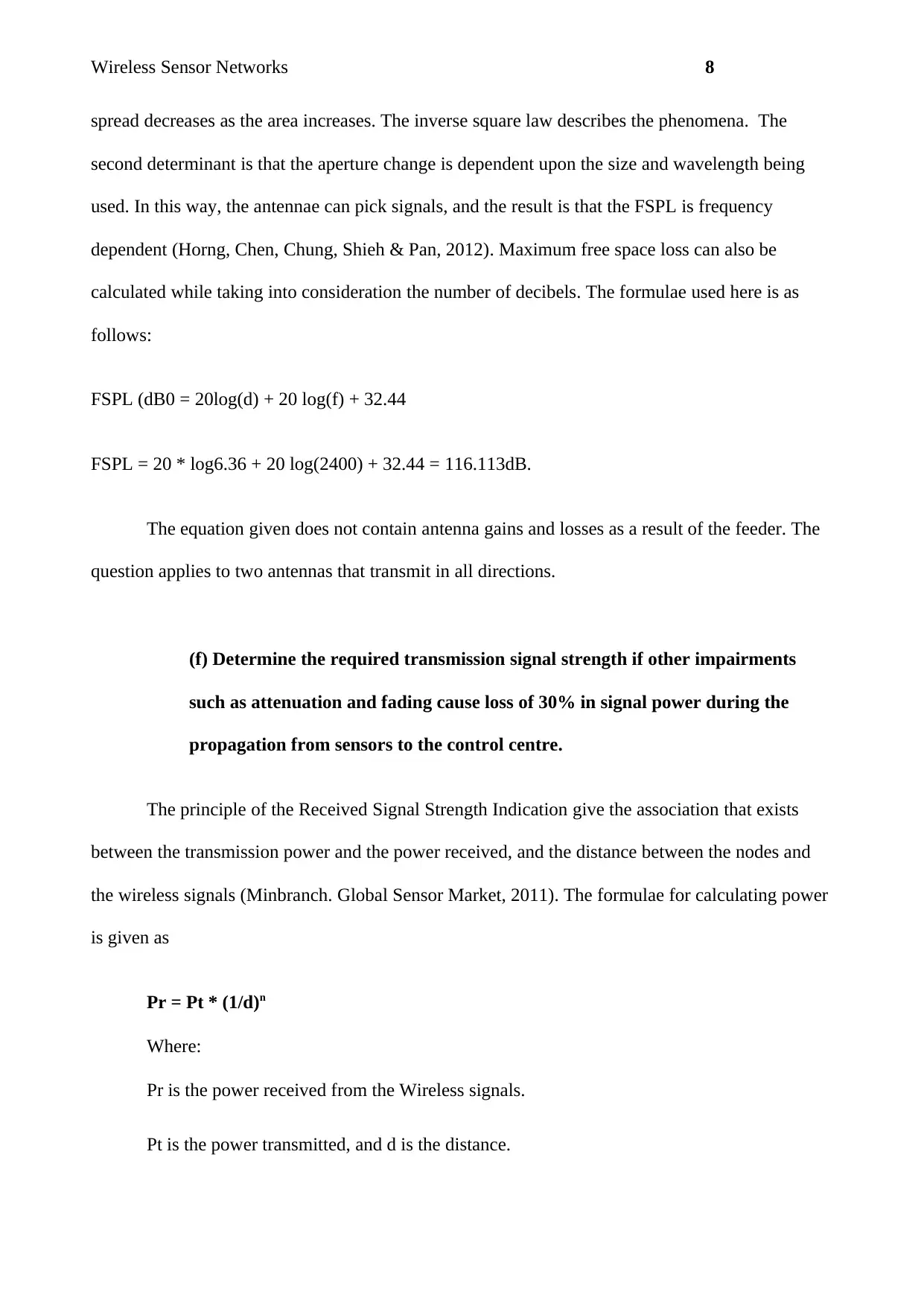
Wireless Sensor Networks8 spread decreases as the area increases. The inverse square law describes the phenomena. The second determinant is that the aperture change is dependent upon the size and wavelength being used. In this way, the antennae can pick signals, and the result is that the FSPL is frequency dependent (Horng, Chen, Chung, Shieh & Pan, 2012).Maximum free space loss can also be calculated while taking into consideration the number of decibels. The formulae used here is as follows: FSPL (dB0 = 20log(d) + 20 log(f) + 32.44 FSPL = 20 * log6.36 + 20 log(2400) + 32.44 =116.113dB. The equation given does not contain antenna gains and losses as a result of the feeder. The question applies to two antennas that transmit in all directions. (f) Determine the required transmission signal strength if other impairments such as attenuation and fading cause loss of 30% in signal power during the propagation from sensors to the control centre. The principle of the Received Signal Strength Indication give the association that exists between the transmission power and the power received, and the distance between the nodes and the wireless signals (Minbranch. Global Sensor Market, 2011). The formulae for calculating power is given as Pr = Pt * (1/d)n Where: Pr is the power received from the Wireless signals. Pt is the power transmitted, and d is the distance.
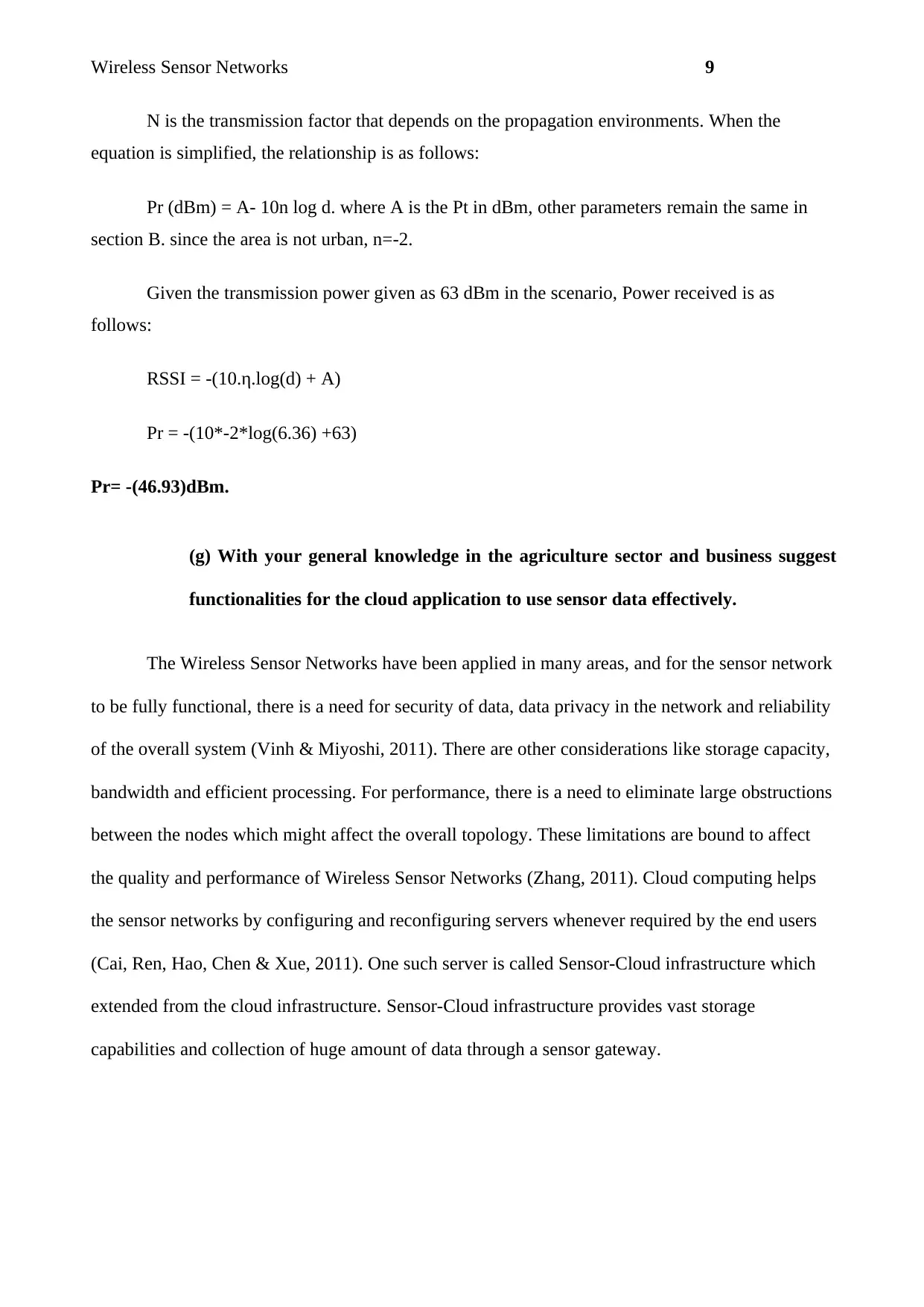
Wireless Sensor Networks9 N is the transmission factor that depends on the propagation environments. When the equation is simplified, the relationship is as follows: Pr (dBm) = A- 10n log d. where A is the Pt in dBm, other parameters remain the same in section B. since the area is not urban, n=-2. Given the transmission power given as 63 dBm in the scenario, Power received is as follows: RSSI = -(10.η.log(d) +A) Pr = -(10*-2*log(6.36) +63) Pr= -(46.93)dBm. (g) With your general knowledge in the agriculture sector and business suggest functionalities for the cloud application to use sensor data effectively. The Wireless Sensor Networks have been applied in many areas, and for the sensor network to be fully functional, there is a need for security of data, data privacy in the network and reliability of the overall system (Vinh & Miyoshi, 2011). There are other considerations like storage capacity, bandwidth and efficient processing. For performance, there is a need to eliminate large obstructions between the nodes which might affect the overall topology. These limitations are bound to affect the quality and performance of Wireless Sensor Networks (Zhang, 2011). Cloud computing helps the sensor networks by configuring and reconfiguring servers whenever required by the end users (Cai, Ren, Hao, Chen & Xue, 2011). One such server is called Sensor-Cloud infrastructure which extended from the cloud infrastructure. Sensor-Cloud infrastructure provides vast storage capabilities and collection of huge amount of data through a sensor gateway.
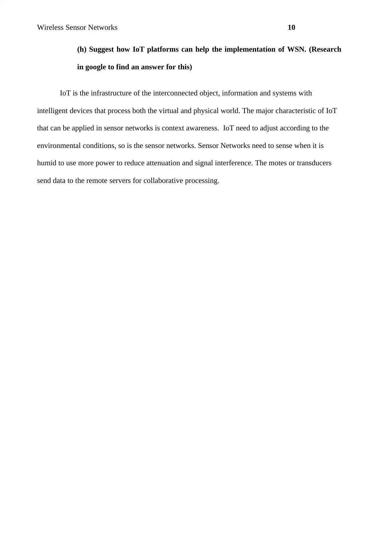
Wireless Sensor Networks10 (h) Suggest how IoT platforms can help the implementation of WSN. (Research in google to find an answer for this) IoT is the infrastructure of the interconnected object, information and systems with intelligent devices that process both the virtual and physical world. The major characteristic of IoT that can be applied in sensor networks is context awareness. IoT need to adjust according to the environmental conditions, so is the sensor networks. Sensor Networks need to sense when it is humid to use more power to reduce attenuation and signal interference. The motes or transducers send data to the remote servers for collaborative processing.
Secure Best Marks with AI Grader
Need help grading? Try our AI Grader for instant feedback on your assignments.
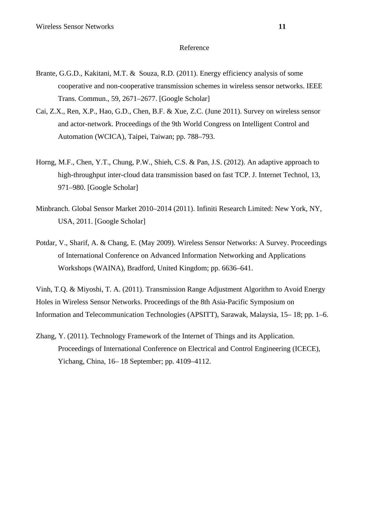
Wireless Sensor Networks11 Reference Brante, G.G.D., Kakitani, M.T. & Souza, R.D. (2011). Energy efficiency analysis of some cooperative and non-cooperative transmission schemes in wireless sensor networks. IEEE Trans. Commun., 59, 2671–2677. [Google Scholar] Cai, Z.X., Ren, X.P., Hao, G.D., Chen, B.F. & Xue, Z.C. (June 2011). Survey on wireless sensor and actor-network. Proceedings of the 9th World Congress on Intelligent Control and Automation (WCICA), Taipei, Taiwan; pp. 788–793. Horng, M.F., Chen, Y.T., Chung, P.W., Shieh, C.S. & Pan, J.S. (2012). An adaptive approach to high-throughput inter-cloud data transmission based on fast TCP. J. Internet Technol, 13, 971–980. [Google Scholar] Minbranch. Global Sensor Market 2010–2014 (2011). Infiniti Research Limited: New York, NY, USA, 2011. [Google Scholar] Potdar, V., Sharif, A. & Chang, E. (May 2009). Wireless Sensor Networks: A Survey. Proceedings of International Conference on Advanced Information Networking and Applications Workshops (WAINA), Bradford, United Kingdom; pp. 6636–641. Vinh, T.Q. & Miyoshi, T. A. (2011). Transmission Range Adjustment Algorithm to Avoid Energy Holes in Wireless Sensor Networks. Proceedings of the 8th Asia-Pacific Symposium on Information and Telecommunication Technologies (APSITT), Sarawak, Malaysia, 15– 18; pp. 1–6. Zhang, Y. (2011). Technology Framework of the Internet of Things and its Application. Proceedings of International Conference on Electrical and Control Engineering (ICECE), Yichang, China, 16– 18 September; pp. 4109–4112.