FEA Analysis of Bracket Design: Material Properties and Design Improvements
Added on 2022-10-17
6 Pages1613 Words132 Views
1. With a documented rationale to explain what you would consider to be the:
a. Appropriate fixtures applied to the model to replicate real life application
There are multiple applications where brackets are used to connect and hold
different parts. For example, brackets are used in mounting, connecting different
parts, transferring loads etc. In real life applications, the holes provided in bracket
called ‘counter-bores’ should be considered as fixture at the inside face. While
bracket is installed, counter-bores are used to screw attach bracket with other
rigid parts hence bracket is constrained in all directions at counter-bore location.
b. Appropriate loads applied to the model to replicate real life application
As per the intended application, once brackets are mounted on counter-bores,
hook end of the bracket is used to attach either to a bearing or some other
assembly part. All the loads are transferred through the hook end, hence it is
used to apply real life loads on bracket.
2. When conducting FEA analysis, the material from which the component to be
analyzed must be entered into the model. Explain which material properties are
important and the impact to both the study and the obtained results if an incorrect
material is simulated.
As per drawing of bracket, the material to be used, is 1060 Aluminium alloy. To access
bracket’s performance (displacement, stresses) for the applied load using finite element
analysis, both linear and non-linear properties of the material are required. If calculated
stresses using finite element analysis in the bracket are within the elastic regime i.e.
maximum equivalent stress (von Mises’ stress) in the model is less than yield strength of
the material, then only elastic properties of the material are required which are
mentioned in Table 1. The stresses and strains developed in the model are in elastic
regime of the material i.e. no permanent deformation occurs.
Material property Typical value (1060 Al Alloy) Units
Elastic Modulus ~70E9 Pa OR N/m2
Poisson’s ratio 0.3 -
Elastic modulus represents stiffness of the material. Poisson’s ratio is the negative of
ratio of lateral distortion to axial distortion. Other than mentioned properties, density of
the material can also be used. Other than these, Yield strength of the material should be
defined to assess design’s performance. If the maximum equivalent stress (von Mises’
stress) exceeds yield strength of the material, part is considered failed. In that case,
either higher strength material or re-design of the part is required. Depending on the
material behavior, these properties are defined. Most of the solid metals behave
isotropic i.e. properties are same in all the directions irrespective of loading. But specially
processes metals and polymers exhibit different properties in different direction i.e.
Anisotropy. That requires the elastic modulus and poisson’s ratio to be defined in 3
different directions to accurately capture material behavior.
If due to applied load, the maximum equivalent stress in the model exceeds yield
strength of the material, then non-linear finite element analysis is required. Additional
material properties required for this kind of analysis is stress-strain relationship. Different
non-linear models are available to fit experimentally obtained stress-strain relationship,
most commonly used in Hollomon’s equation (or power law) shown in equation 1.
σ =K εn Eq .1
Where σ is plastic stress, K is strength coefficient, ε is plastic strain and n is strain
hardening exponent. Few finite element codes accept stress-strain points as input and
internally fit a curve to access during analysis.
If during an analysis, incorrect material properties are used, it will result in incorrect
stress and displacement results hence resulting in incorrect design of bracket. For
example, if elastic modulus is entered as 120E9 N/m2 which is higher than elastic
modulus of intended material 1060 Al alloy (elastic modulus = 70E9 N/m2). In this case,
the displacements calculated will be comparatively lower for same applied loads and
boundary conditions since defined higher elastic modulus makes material stiffer.
Although we will get same maximum equivalent stress value from finite element analysis
(if loads are not changed) because as per the formulation, stresses are independent of
elastic modulus. Factor of safety is defined as yield strength of the material divided by
maximum equivalent stress in the part during functional loading. As a part of design
process, a specific value of factor of safety is targeted depending on the application.
Typical value of factor of safety ranges from 5 to 10. As an example, for a part design to
qualify at desired load with factor of safety of 10, maximum von Mises’ should be less
than yield strength divided by 10.
Summary and Conclusions from the study results of FEA:
A bracket geometry is analyzed using finite element analysis method to assess its
design performance for applied load and boundary conditions. As per the drawing,
bottom of the counter-bored faces are used as fixture to fix the bracket and load is
applied at curved angle of the bracket. Fixity at counter-bored ends is defined as a
boundary condition while curved angle (hook) is used to apply loading condition.
Meshing is another important aspect of finite element analysis. If during analysis, mesh
size is not appropriately chosen, obtained results can be significantly erroneous. Mesh
convergence studies are usually performed onto the part by increasing the minimum
element size and studying the change in stresses at particular location. After a certain
element size increase, change in predicted stress value from finite element analysis
becomes almost constant. At this point, the minimum element size should be chosen to
study results.
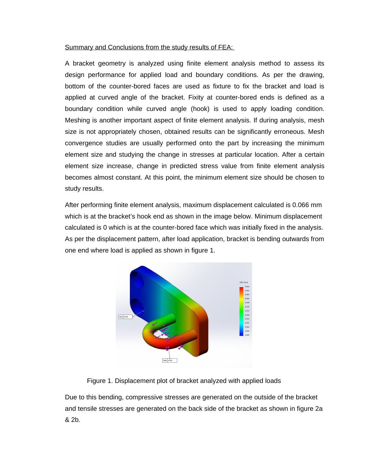
After performing finite element analysis, maximum displacement calculated is 0.066 mm
which is at the bracket’s hook end as shown in the image below. Minimum displacement
calculated is 0 which is at the counter-bored face which was initially fixed in the analysis.
As per the displacement pattern, after load application, bracket is bending outwards from
one end where load is applied as shown in figure 1.
Figure 1. Displacement plot of bracket analyzed with applied loads
Due to this bending, compressive stresses are generated on the outside of the bracket
and tensile stresses are generated on the back side of the bracket as shown in figure 2a
& 2b.
A bracket geometry is analyzed using finite element analysis method to assess its
design performance for applied load and boundary conditions. As per the drawing,
bottom of the counter-bored faces are used as fixture to fix the bracket and load is
applied at curved angle of the bracket. Fixity at counter-bored ends is defined as a
boundary condition while curved angle (hook) is used to apply loading condition.
Meshing is another important aspect of finite element analysis. If during analysis, mesh
size is not appropriately chosen, obtained results can be significantly erroneous. Mesh
convergence studies are usually performed onto the part by increasing the minimum
element size and studying the change in stresses at particular location. After a certain
element size increase, change in predicted stress value from finite element analysis
becomes almost constant. At this point, the minimum element size should be chosen to
study results.
After performing finite element analysis, maximum displacement calculated is 0.066 mm
which is at the bracket’s hook end as shown in the image below. Minimum displacement
calculated is 0 which is at the counter-bored face which was initially fixed in the analysis.
As per the displacement pattern, after load application, bracket is bending outwards from
one end where load is applied as shown in figure 1.
Figure 1. Displacement plot of bracket analyzed with applied loads
Due to this bending, compressive stresses are generated on the outside of the bracket
and tensile stresses are generated on the back side of the bracket as shown in figure 2a
& 2b.
End of preview
Want to access all the pages? Upload your documents or become a member.
Related Documents
Finite Element Analysislg...
|9
|1446
|365
Milling Process Parameterslg...
|20
|3817
|287
Simulation of Plastic Analysis - Study Properties, Material Properties, Loads and Fixtures, Mesh Information, Study Resultslg...
|11
|619
|163
Stress Analysis of Bracketlg...
|6
|516
|200
Structure finite element analysis for applied loads and boundarylg...
|10
|1580
|18