TMA 2: Two-Port Networks Analysis and Transmission Line Problems
VerifiedAdded on 2022/09/14
|12
|838
|39
Homework Assignment
AI Summary
This document provides a comprehensive solution to a Tutor Marked Assignment (TMA) in Electrical and Electronic Principles, focusing on two-port networks and transmission line theory. The assignment begins by determining the z-parameters of a two-port network using mesh analysis. It then explores transmission line characteristics, including phase change calculations, input impedance determination for a terminated line, and the definitions of distortion-less and lossless transmission lines. Further, the document calculates secondary coefficients of a transmission line, insertion loss of a T-network, and analyzes a high-voltage transmission line using ABCD parameters. Finally, it investigates the estimation of primary line coefficients using a nominal T-model. The solution includes detailed calculations, formulas, and explanations for each problem, providing a thorough understanding of the concepts involved.

1
Student
Instructor
Two Port Network
Date
Student
Instructor
Two Port Network
Date
Paraphrase This Document
Need a fresh take? Get an instant paraphrase of this document with our AI Paraphraser
2
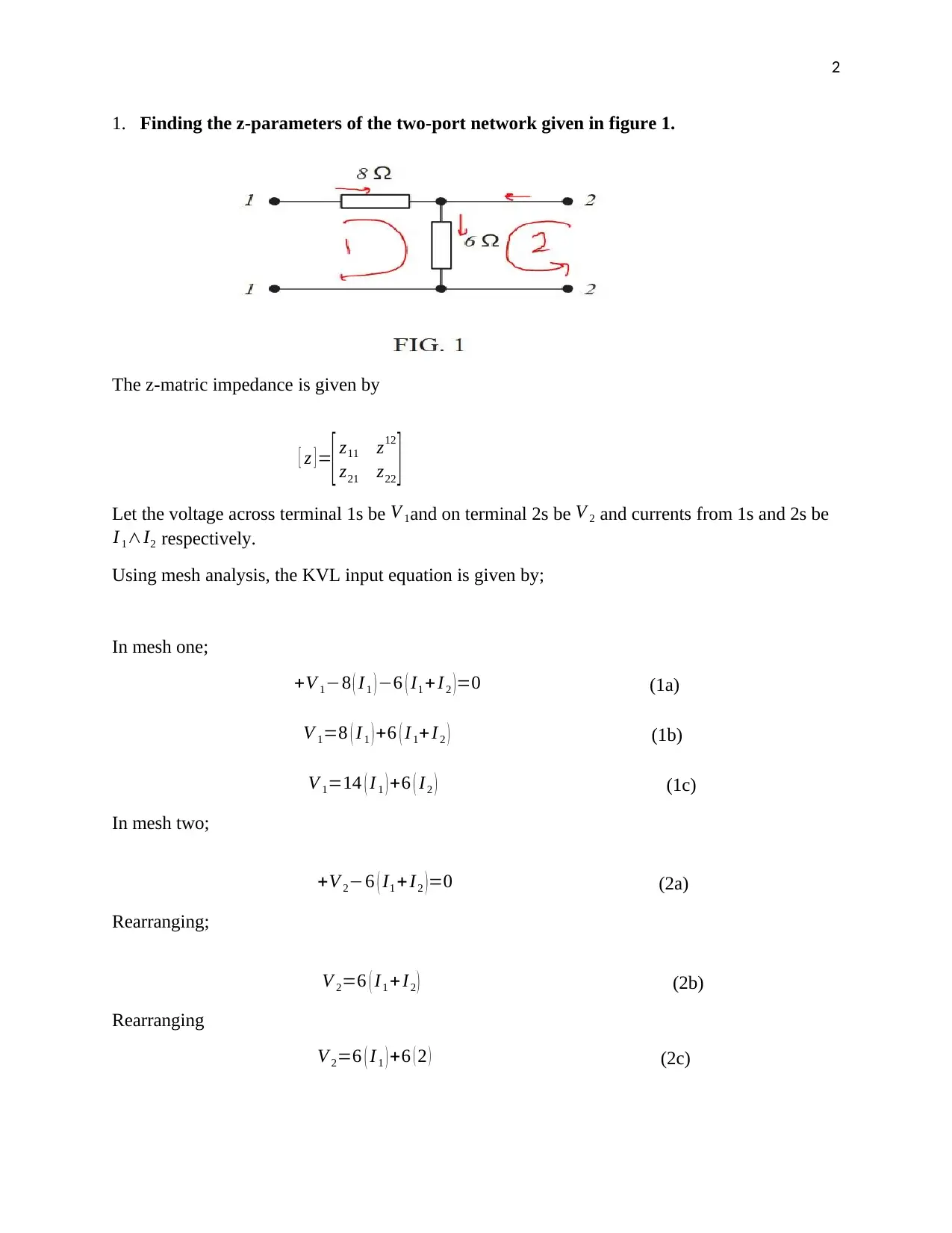
1. Finding the z-parameters of the two-port network given in figure 1.
The z-matric impedance is given by
[ z ] =
[ z11 z12
z21 z22 ]
Let the voltage across terminal 1s be V 1and on terminal 2s be V 2 and currents from 1s and 2s be
I 1∧I2 respectively.
Using mesh analysis, the KVL input equation is given by;
In mesh one;
+V 1−8 ( I1 ) −6 ( I1 +I 2 )=0 (1a)
V 1=8 ( I1 ) +6 ( I 1+ I 2 ) (1b)
V 1=14 ( I 1 ) +6 ( I 2 ) (1c)
In mesh two;
+V 2−6 ( I1 + I2 )=0 (2a)
Rearranging;
V 2=6 ( I1 + I2 ) (2b)
Rearranging
V 2=6 ( I1 ) +6 ( 2 ) (2c)
3
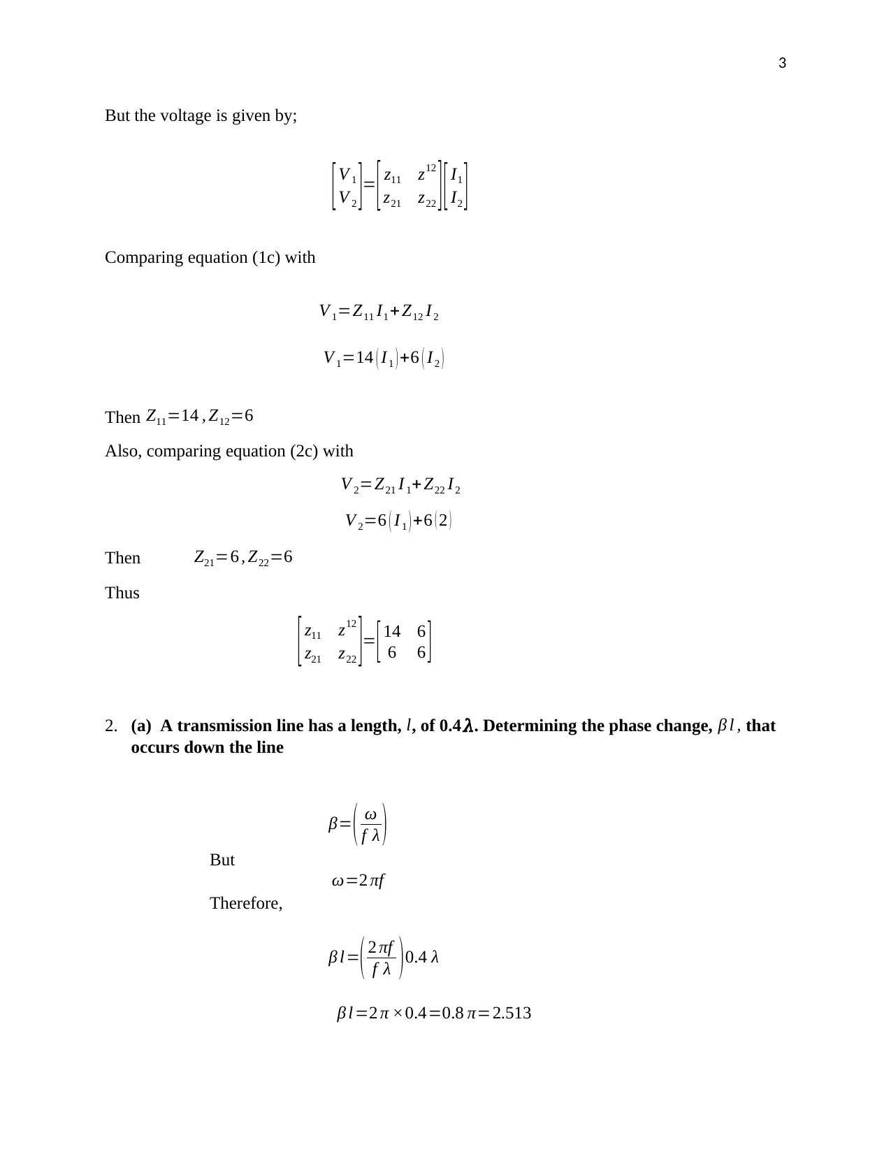
But the voltage is given by;
[V 1
V 2 ]= [ z11 z12
z21 z22 ] [ I1
I2 ]
Comparing equation (1c) with
V 1=Z11 I1 + Z12 I 2
V 1=14 ( I1 ) +6 ( I2 )
Then Z11=14 , Z12=6
Also, comparing equation (2c) with
V 2=Z21 I 1+Z22 I2
V 2=6 ( I 1 ) +6 ( 2 )
Then Z21=6 , Z22=6
Thus
[ z11 z12
z21 z22 ]= [ 14 6
6 6 ]
2. (a) A transmission line has a length, l, of 0.4𝜆. Determining the phase change, β l , that
occurs down the line
β= ( ω
f λ )
But
ω=2 πf
Therefore,
β l=( 2 πf
f λ )0.4 λ
β l =2 π ×0.4=0.8 π=2.513
⊘ This is a preview!⊘
Do you want full access?
Subscribe today to unlock all pages.

Trusted by 1+ million students worldwide
4
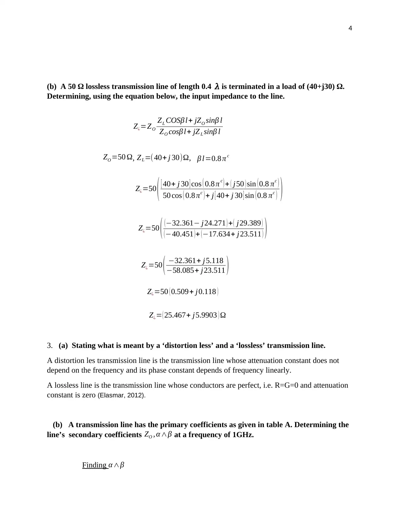
(b) A 50 Ω lossless transmission line of length 0.4 𝜆 is terminated in a load of (40+j30) Ω.
Determining, using the equation below, the input impedance to the line.
Z¿=ZO
ZL COSβ l+ jZO sinβ l
ZO cosβ l+ jZ L sinβ l
ZO =50 Ω, ZL=(40+ j 30)Ω, β l=0.8 π c
Z¿=50 ( [ 40+ j 30 ] cos ( 0.8 π c ) + ( j50 ) sin ( 0.8 πc )
50 cos ( 0.8 πc ) + j [ 40+ j 30 ] sin ( 0.8 πc ) )
Z¿=50 ( ( −32.361− j24.271 ) + ( j29.389 )
( −40.451 ) + ( −17.634+ j23.511 ) )
Z¿=50 ( −32.361+ j 5.118
−58.085+ j23.511 )
Z¿=50 ( 0.509+ j0.118 )
Z¿= ( 25.467+ j5.9903 ) Ω
3. (a) Stating what is meant by a ‘distortion less’ and a ‘lossless’ transmission line.
A distortion les transmission line is the transmission line whose attenuation constant does not
depend on the frequency and its phase constant depends of frequency linearly.
A lossless line is the transmission line whose conductors are perfect, i.e. R=G=0 and attenuation
constant is zero (Elasmar, 2012).
(b) A transmission line has the primary coefficients as given in table A. Determining the
line’s secondary coefficients ZO , α ∧β at a frequency of 1GHz.
Finding α ∧β
Paraphrase This Document
Need a fresh take? Get an instant paraphrase of this document with our AI Paraphraser
5
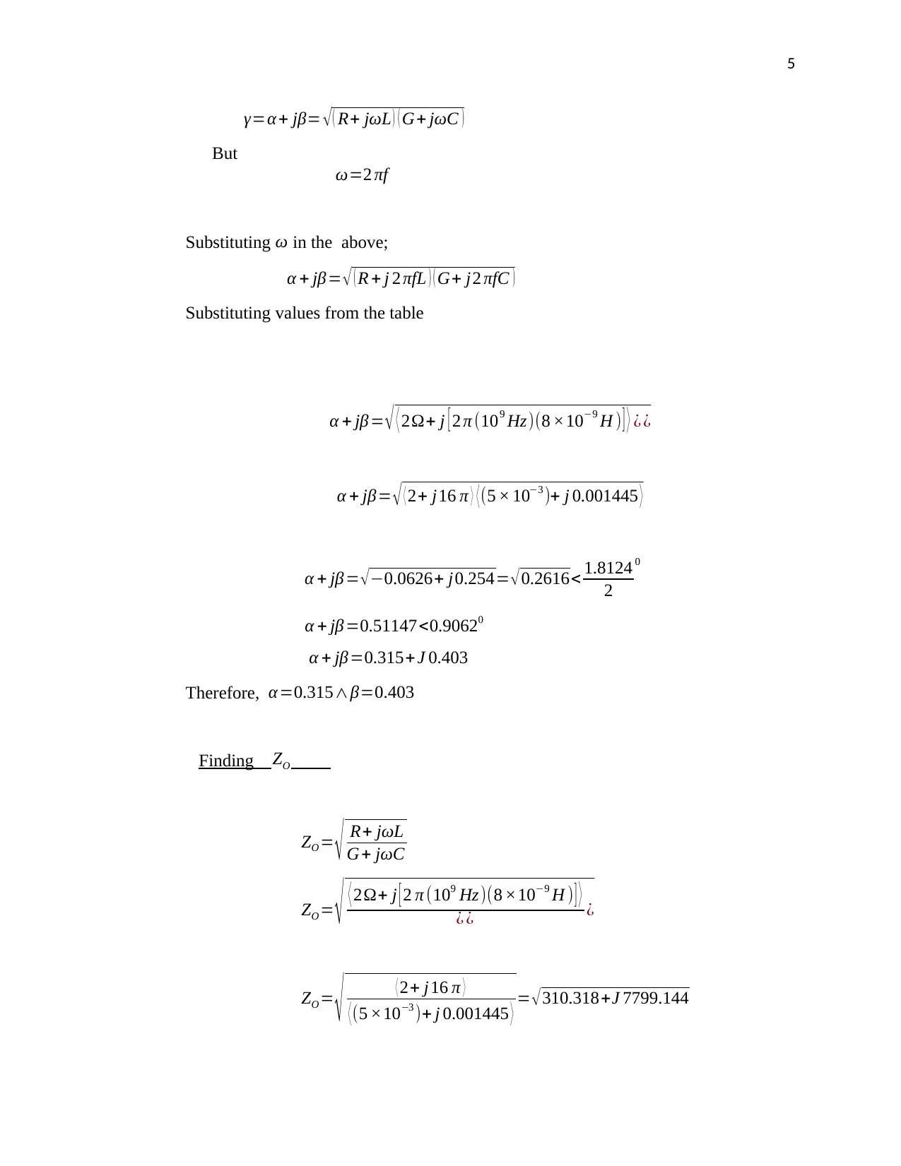
γ=α + jβ= √ ( R+ jωL ) ( G+ jωC )
But
ω=2 πf
Substituting ω in the above;
α + jβ= √ ( R + j 2 πfL ) ( G+ j2 πfC )
Substituting values from the table
α + jβ= √ ⟨ 2Ω+ j [ 2 π (109 Hz)(8 ×10⁻⁹ H ) ] ⟩ ¿ ¿
α + jβ= √ ⟨ 2+ j16 π ⟩ ⟨ (5 × 10⁻³ )+ j 0.001445 ⟩
α + jβ = √ −0.0626+ j0.254= √ 0.2616< 1.8124
2
0
α + jβ=0.51147<0.90620
α + jβ=0.315+ J 0.403
Therefore, α=0.315∧β=0.403
Finding ZO
ZO = √ R+ jωL
G+ jωC
ZO = √ ⟨ 2Ω+ j [ 2 π (109 Hz)(8 ×10⁻⁹ H ) ] ⟩
¿ ¿ ¿
ZO =
√ ⟨ 2+ j16 π ⟩
⟨ (5 ×10⁻³ )+ j 0.001445 ⟩ = √ 310.318+J 7799.144
6
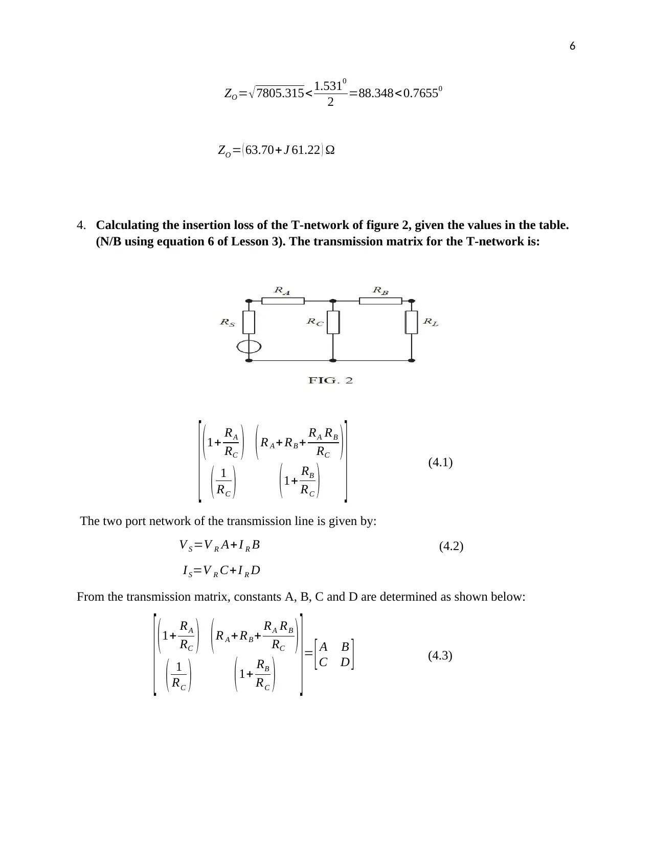
ZO = √7805.315<1.5310
2 =88.348< 0.76550
ZO = ( 63.70+ J 61.22 ) Ω
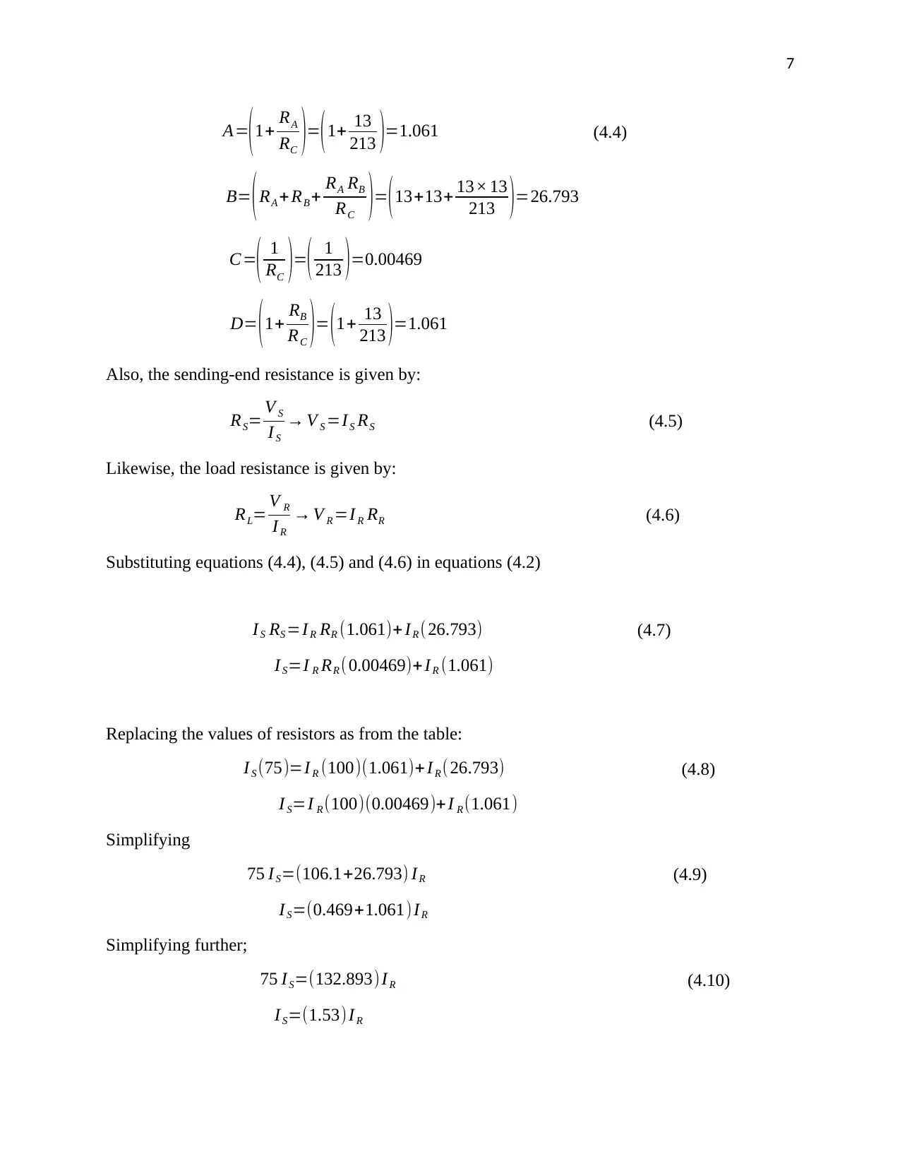
4. Calculating the insertion loss of the T-network of figure 2, given the values in the table.
(N/B using equation 6 of Lesson 3). The transmission matrix for the T-network is:
[ ( 1+ RA
RC ) ( R A + RB + RA RB
RC )
( 1
RC ) ( 1+ RB
RC ) ] (4.1)
The two port network of the transmission line is given by:
V S =V R A+I R B (4.2)
IS=V R C+ I R D
From the transmission matrix, constants A, B, C and D are determined as shown below:
[ ( 1+ RA
RC ) ( R A +RB + RA RB
RC )
( 1
RC ) ( 1+ RB
RC ) ] = [ A B
C D ] (4.3)
⊘ This is a preview!⊘
Do you want full access?
Subscribe today to unlock all pages.

Trusted by 1+ million students worldwide
7
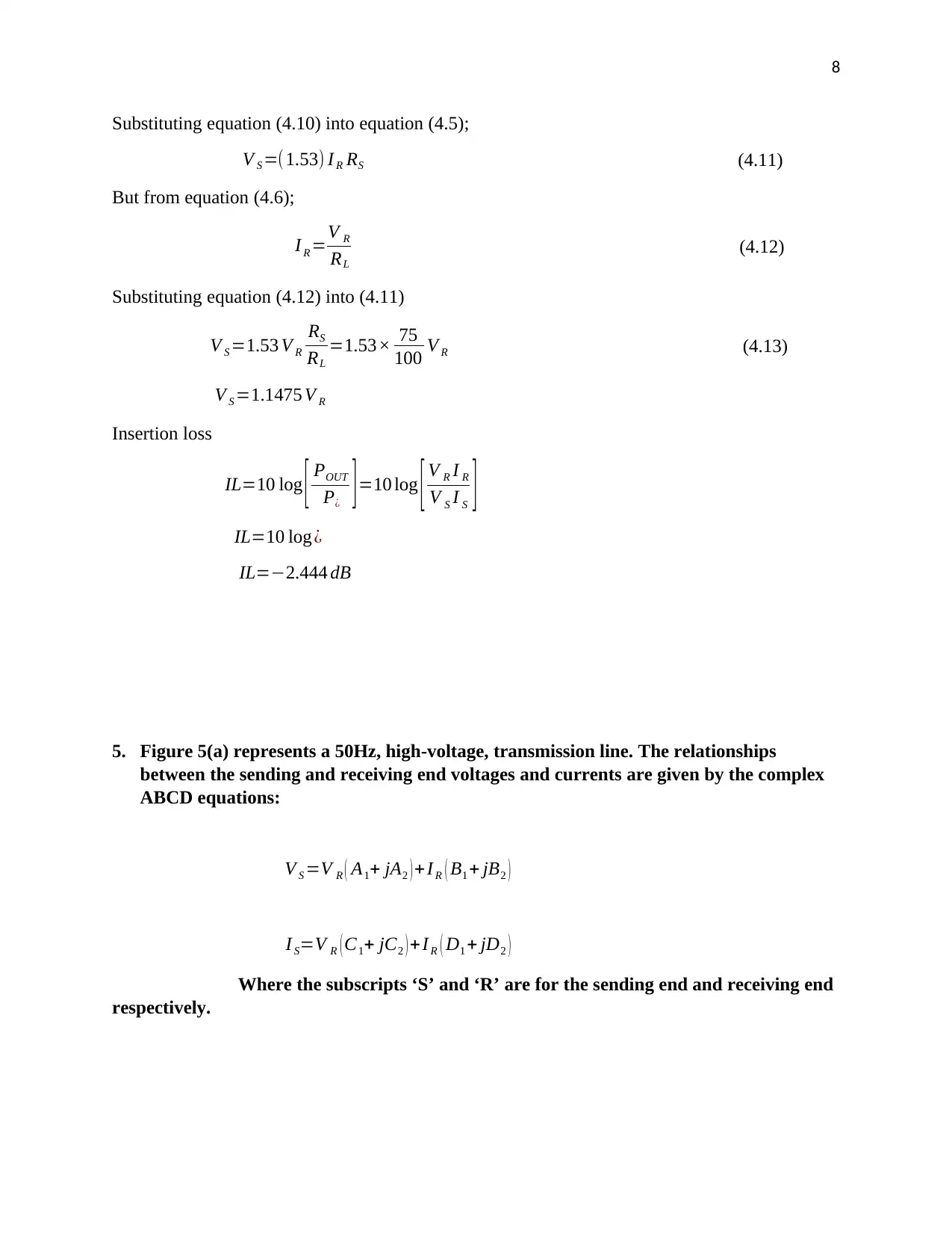
A=
(1+ RA
RC )=(1+ 13
213 )=1.061 (4.4)
B= (RA +RB + RA RB
RC )= (13+13+ 13× 13
213 )=26.793
C=( 1
RC )=( 1
213 )=0.00469
D= (1+ RB
RC )= (1+ 13
213 )=1.061
Also, the sending-end resistance is given by:
RS= V S
I S
→ V S =IS RS (4.5)
Likewise, the load resistance is given by:
RL= V R
I R
→ V R =I R RR (4.6)
Substituting equations (4.4), (4.5) and (4.6) in equations (4.2)
IS RS =I R RR (1.061)+ IR (26.793) (4.7)
I S=I R RR (0.00469)+ IR (1.061)
Replacing the values of resistors as from the table:
I S (75)=I R (100)(1.061)+ I R ( 26.793) (4.8)
I S=I R (100)(0.00469)+ I R (1.061)
Simplifying
75 I S=(106.1+26.793) IR (4.9)
IS=(0.469+1.061) IR
Simplifying further;
75 IS=(132.893) I R (4.10)
I S=(1.53) IR
Paraphrase This Document
Need a fresh take? Get an instant paraphrase of this document with our AI Paraphraser
8
Substituting equation (4.10) into equation (4.5);
V S =(1.53) I R RS (4.11)
But from equation (4.6);
I R =V R
RL
(4.12)
Substituting equation (4.12) into (4.11)
V S =1.53 V R
RS
RL
=1.53× 75
100 V R (4.13)
V S =1.1475 V R
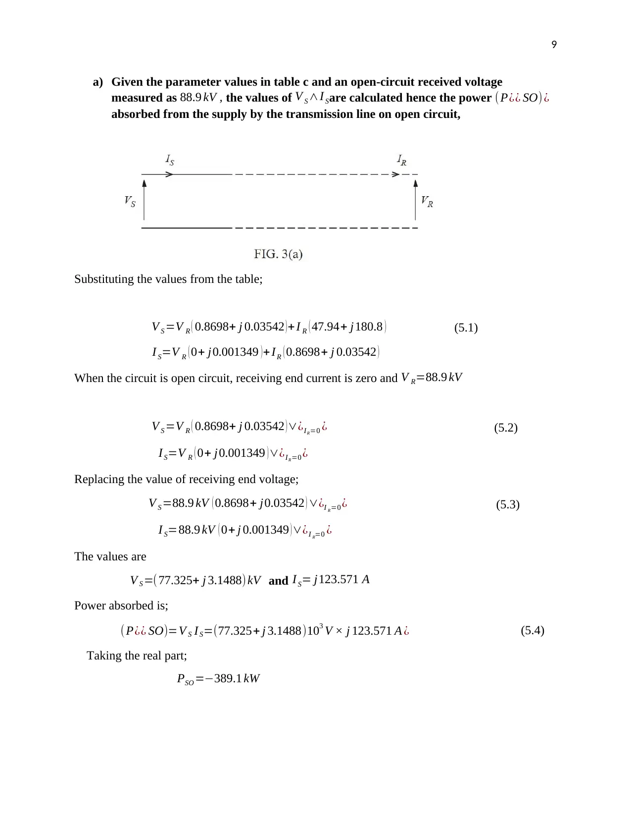
Insertion loss
IL=10 log [ POUT
P¿ ] =10 log [ V R I R
V S I S ]
IL=10 log¿
IL=−2.444 dB
5. Figure 5(a) represents a 50Hz, high-voltage, transmission line. The relationships
between the sending and receiving end voltages and currents are given by the complex
ABCD equations:
V S =V R ( A1+ jA2 ) + I R ( B1 + jB2 )
I S=V R ( C1+ jC2 ) +I R ( D1 + jD2 )
Where the subscripts ‘S’ and ‘R’ are for the sending end and receiving end
respectively.
9
a) Given the parameter values in table c and an open-circuit received voltage
measured as 88.9 kV , the values of V S ∧I Sare calculated hence the power (P¿¿ SO) ¿
absorbed from the supply by the transmission line on open circuit,
Substituting the values from the table;
V S =V R ( 0.8698+ j 0.03542 )+ I R ( 47.94+ j180.8 ) (5.1)
I S=V R ( 0+ j0.001349 ) + IR ( 0.8698+ j 0.03542 )
When the circuit is open circuit, receiving end current is zero and V R=88.9 kV
V S =V R ( 0.8698+ j 0.03542 ) ∨¿IR=0 ¿ (5.2)
IS=V R ( 0+ j0.001349 )∨¿IR=0 ¿
Replacing the value of receiving end voltage;
V S =88.9 kV ( 0.8698+ j0.03542 ) ∨¿I R=0 ¿ (5.3)
I S=88.9 kV ( 0+ j 0.001349 ) ∨¿I R=0 ¿
The values are
V S =( 77.325+ j 3.1488) kV and I S= j123.571 A
Power absorbed is;
(P¿¿ SO)=V S IS=(77.325+ j 3.1488)103 V × j 123.571 A ¿ (5.4)
Taking the real part;
PSO =−389.1 kW
⊘ This is a preview!⊘
Do you want full access?
Subscribe today to unlock all pages.

Trusted by 1+ million students worldwide
10
b) If the line is modelled by the T-circuit of figure 3(b), it was seen whether we can
estimate the primary line coefficients R, L, G and C. The line is 50km long.
The sending end and receiving end equation governing nominal T-model of the transmission line
is given by;
V S =V R [1+ YZ
2 ]+ I R [1+ YZ
4 ]Z (5.5)
IS=V R Y + I R [ 1+ YZ
2 ]
At no load condition when the receiving end is open circuit the receiving end current I R is zero,
thus equations (5.5) becomes;
V S =V R [ 1+ YZ
2 ] (5.6)
IS=V R Y
Substituting values found in equation (5.3) into equations (5.6), we get;
( 77.325+ j3.1488 ) kV =88.9 kV [ 1+ YZ
2 ] (5.7)
j 123.571=88.9 ×10³ V ( Y )
Simplifying equations (5.7) results to;
Paraphrase This Document
Need a fresh take? Get an instant paraphrase of this document with our AI Paraphraser
11
[1+ YZ
2 ]= ( 0.8698+ j0.0354 ) (5.8a)
Y =J 0.00139 (5.8b)
Substituting the value of equations (5.8b) into (5.8a)
[ 1+ j0.00139 Z
2 ] = ( 0.8698+ j 0.0354 ) (5.9)
( 2+ j0.00139 Z ) =2 ( 0.8698+ j 0.0354 )
j 0.00139 Z =1.7396−2+ j0.0354
j 0.00139 Z =−0.2604+ j0.0354
Impedance Z per length is found to be;
Z=−0.2604+ j0.0354
j 0.00139
Z=25.46+J 187.33 Ω (5.10)
Conductance Y per length was found as;
Y =J 0.00139 (5.11)
Finding series resistance and inductance from equation (5.10).
R+ j2 πfL=50 km(25.46+ J 187.33)Ω (5.12)
R+ j2 πfL=1.273 k Ω+ j9.3665 k Ω
i. Resistance R is
R=1.273 k Ω
ii. Inductance L at 60Hz transmission frequency.
2 πfL=9.3665 k Ω
L= 9.3665 ×1 03
2 π × 60 Hz =24.84 H
L=24.84 H
iii. Finding conductance Y from equation (5.11).
Y km=G− j C
2 πf =50 km × j0.00139
G=0
12
Capacitance C
C=50 × j0.00139 ×2 π × 60 Hz
C=26.2 F
REFERENCE.
Elasmar, M. (2012). Transmission Line. Retrieved 27 August 2019, from
http://site.iugaza.edu.ps/masmar/files/EM_Dis_Ch_11_Part_1.pdf
Capacitance C
C=50 × j0.00139 ×2 π × 60 Hz
C=26.2 F
REFERENCE.
Elasmar, M. (2012). Transmission Line. Retrieved 27 August 2019, from
http://site.iugaza.edu.ps/masmar/files/EM_Dis_Ch_11_Part_1.pdf
⊘ This is a preview!⊘
Do you want full access?
Subscribe today to unlock all pages.

Trusted by 1+ million students worldwide
1 out of 12
Your All-in-One AI-Powered Toolkit for Academic Success.
+13062052269
info@desklib.com
Available 24*7 on WhatsApp / Email
![[object Object]](/_next/static/media/star-bottom.7253800d.svg)
Unlock your academic potential
Copyright © 2020–2026 A2Z Services. All Rights Reserved. Developed and managed by ZUCOL.

