Analysis of Zero Energy Building using ANSYS Software
VerifiedAdded on 2023/06/08
|11
|3022
|261
AI Summary
This paper deals with the analysis of zero energy building using ANSYS software and the suitable method adopted to generate the energy for the building which is renewable and clean. The study will be mostly focusing on the materials used to build zero energy buildings e.g. green plaster, green house, timber etc.
Contribute Materials
Your contribution can guide someone’s learning journey. Share your
documents today.
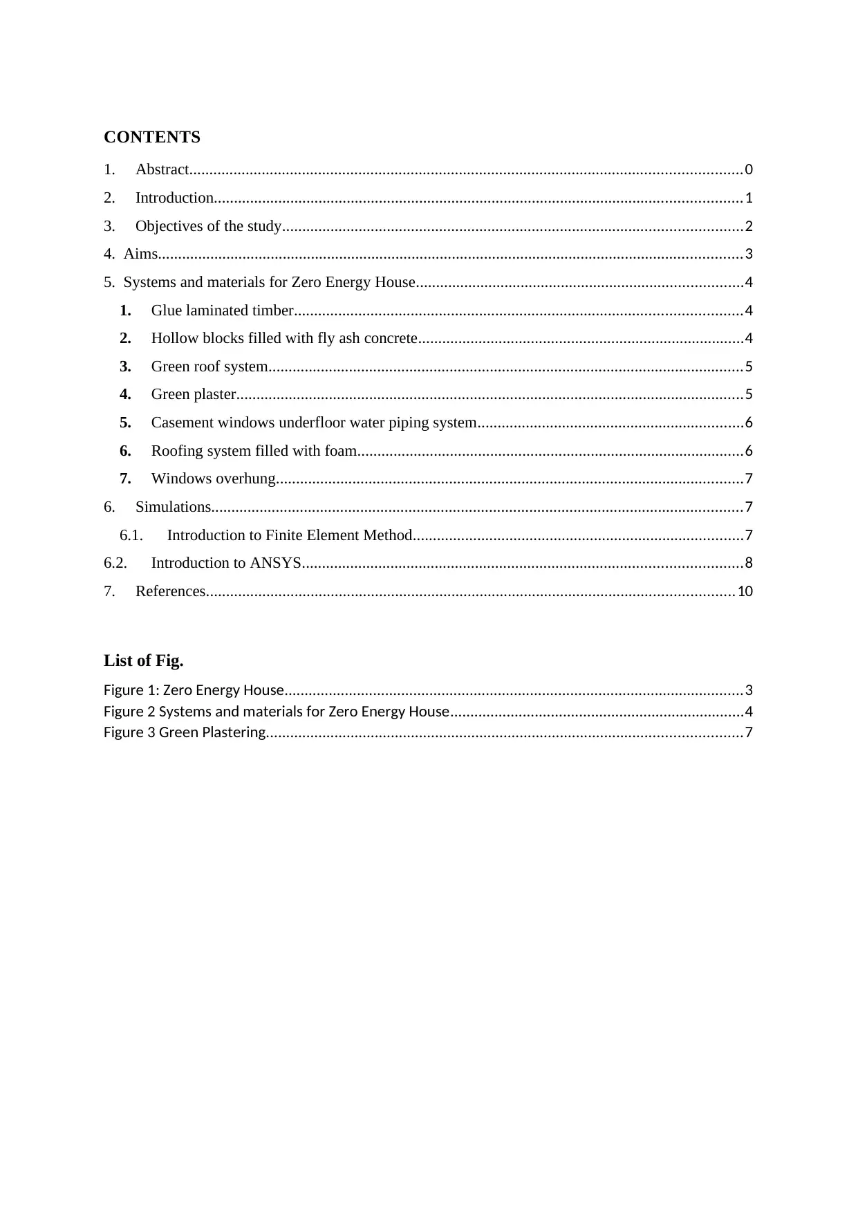
CONTENTS
1. Abstract.........................................................................................................................................0
2. Introduction...................................................................................................................................1
3. Objectives of the study..................................................................................................................2
4. Aims.................................................................................................................................................3
5. Systems and materials for Zero Energy House.................................................................................4
1. Glue laminated timber...............................................................................................................4
2. Hollow blocks filled with fly ash concrete.................................................................................4
3. Green roof system......................................................................................................................5
4. Green plaster..............................................................................................................................5
5. Casement windows underfloor water piping system..................................................................6
6. Roofing system filled with foam................................................................................................6
7. Windows overhung....................................................................................................................7
6. Simulations....................................................................................................................................7
6.1. Introduction to Finite Element Method..................................................................................7
6.2. Introduction to ANSYS.............................................................................................................8
7. References...................................................................................................................................10
List of Fig.
Figure 1: Zero Energy House..................................................................................................................3
Figure 2 Systems and materials for Zero Energy House.........................................................................4
Figure 3 Green Plastering......................................................................................................................7
Secure Best Marks with AI Grader
Need help grading? Try our AI Grader for instant feedback on your assignments.
1. Abstract
This paper deals with the analysis of zero energy building using ANSYS software and the
suitable method adopted to generate the energy for the building which is renewable and
clean. Zero energy building refers to the building that consumes approximately zero energy
and utilizes 100% of the natural resources. They not only protect our environment but also it
provides good quality level of indoor environment. The study will be mostly focusing on the
materials used to build zero energy buildings e.g. green plaster, green house, timber etc. By
the uses of finite element method and ANSYS a conclusion is drawn regarding different
materials used for zero energy building construction. (S., 2015)
2. Introduction
Zero energy building refers to the building that consumes approximately zero energy and
utilizes 100% of the natural resources. These buildings play vital role and contributes majorly
in minimization of carbon emissions and protecting our environment. They not only protect
our environment but also it provides good quality level of indoor environment. They can be
built anywhere in our globe. They have a great potential in eliminating and reducing the
consumption of energy in ordinary buildings. (K. & E., 2012)
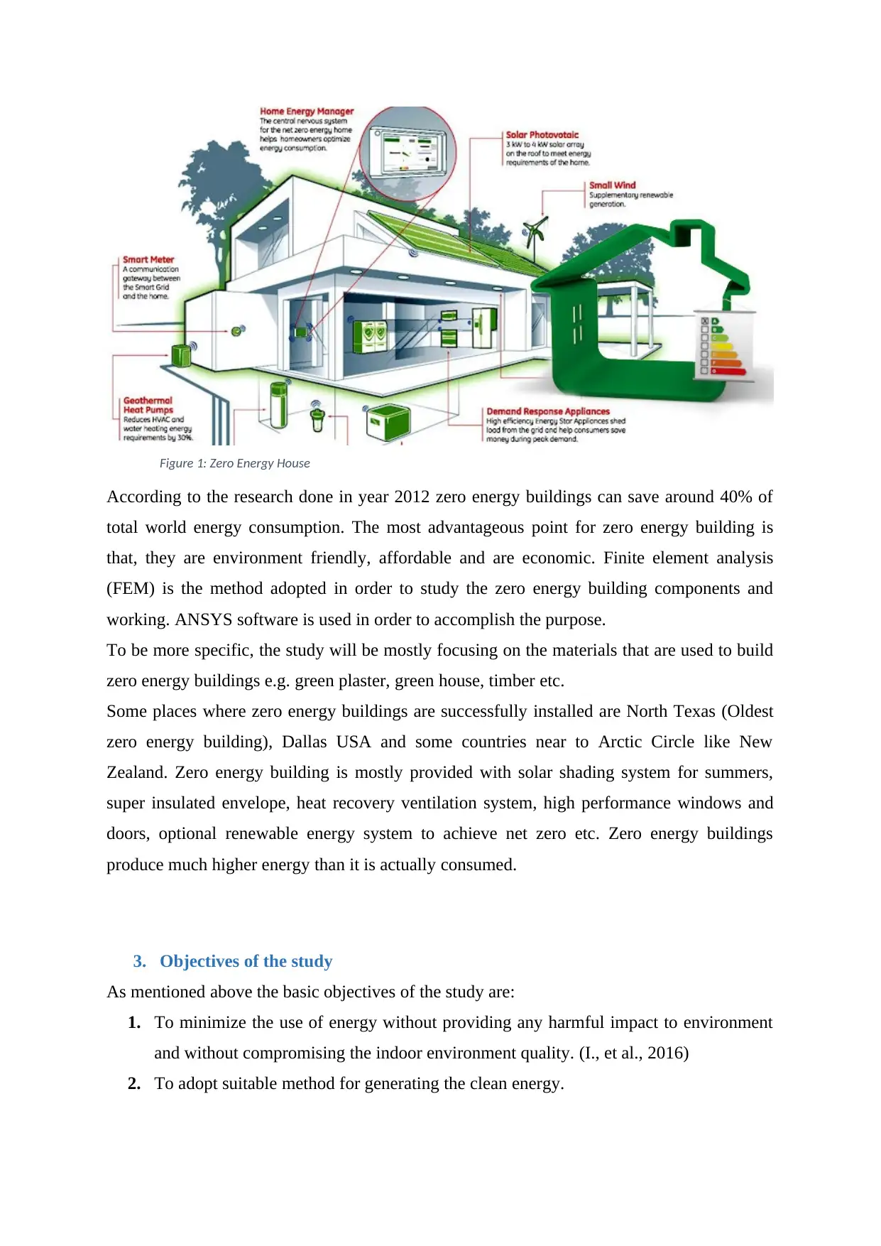
Figure 1: Zero Energy House
According to the research done in year 2012 zero energy buildings can save around 40% of
total world energy consumption. The most advantageous point for zero energy building is
that, they are environment friendly, affordable and are economic. Finite element analysis
(FEM) is the method adopted in order to study the zero energy building components and
working. ANSYS software is used in order to accomplish the purpose.
To be more specific, the study will be mostly focusing on the materials that are used to build
zero energy buildings e.g. green plaster, green house, timber etc.
Some places where zero energy buildings are successfully installed are North Texas (Oldest
zero energy building), Dallas USA and some countries near to Arctic Circle like New
Zealand. Zero energy building is mostly provided with solar shading system for summers,
super insulated envelope, heat recovery ventilation system, high performance windows and
doors, optional renewable energy system to achieve net zero etc. Zero energy buildings
produce much higher energy than it is actually consumed.
3. Objectives of the study
As mentioned above the basic objectives of the study are:
1. To minimize the use of energy without providing any harmful impact to environment
and without compromising the indoor environment quality. (I., et al., 2016)
2. To adopt suitable method for generating the clean energy.
As far the study is concerned in the project, FEM is the method used. Through FEM thermal
properties of the materials and the energy performance of the materials and the system are
analyzed.
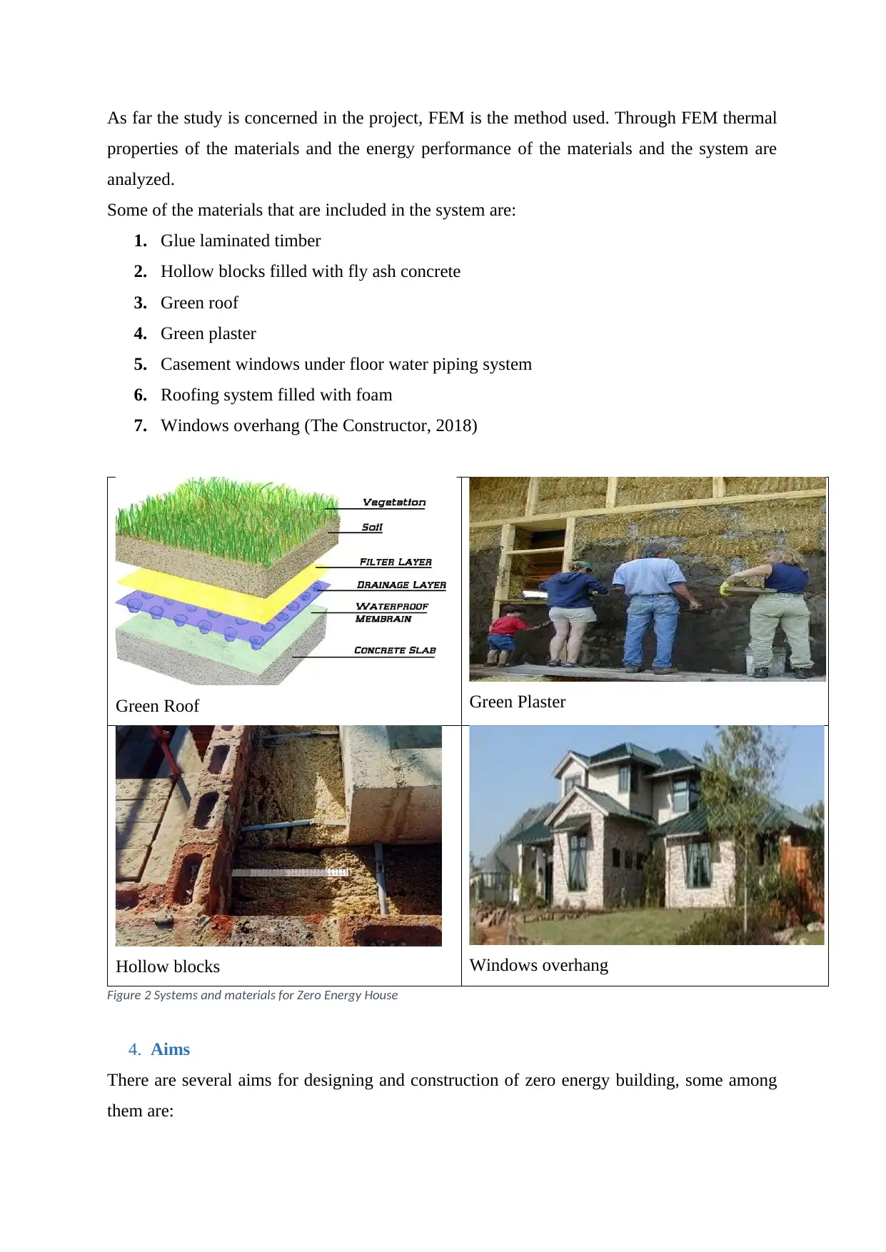
Some of the materials that are included in the system are:
1. Glue laminated timber
2. Hollow blocks filled with fly ash concrete
3. Green roof
4. Green plaster
5. Casement windows under floor water piping system
6. Roofing system filled with foam
7. Windows overhang (The Constructor, 2018)
Green Roof Green Plaster
Hollow blocks Windows overhang
Figure 2 Systems and materials for Zero Energy House
4. Aims
There are several aims for designing and construction of zero energy building, some among
them are:
Secure Best Marks with AI Grader
Need help grading? Try our AI Grader for instant feedback on your assignments.
1. Greenhouse gases and energy efficiency: By maximizing the use of renewable energy
there will be reduction in carbon dioxide and other greenhouse gases emissions that
are generated by ordinary energy production. Not only this, there will be optimization
of household energy usage. (M., 2007)
2. Low embodied energy: The materials that are used in zero energy buildings are
designed such that it requires minimal energy during processing and transportation.
3. Water conservation: In the zero energy buildings there are efficient appliances which
require less water thus reducing wastage.
4. Health and comfort: Zero energy buildings are designed in such a way that the indoor
rooms get good daylight and fresh air supply. This takes care of comfort, health, and
happiness of the people living in it. This causes reduction in medication and the
medical cost.
5. Low pollutant emission: During the construction of zero energy building there is very
low emission of pollutants.
5. Systems and materials for Zero Energy House
1. Glue laminated timber: It is also known as ‘glulam’. According to the engineered
wood association glulam has high strength to weight ratio as compared to steel. It is
stiffer than dimension lumber. It is a form of timber which is commonly used as
structural engineered wood which is used as beams and columns in residential and
requires minimum additional support when it acts as column or other structural span
due to its superior properties. Secondly it has advantage of wood’s natural aesthetics
commercial buildings. The most advantageous thing in glulam is that it is cost
effective as it Wood laminations of timber are positioned according to the effective
stress distribution criteria and the laminates are than glued together to form glulam.
(C., 2013)
2. Hollow blocks filled with fly ash concrete: Fly ash is the fine powder which is the by-
products of burnt pulverized coal. Fly ash is a kind of ash which is extracted from the
flue gases through the process of Electrostatic Precipitator in dry form. This ash is
very fine and they possess good pozzolanic property. Pozzolanic property of the fly
ash makes fly ash a resource for making cement. This cement is used for building zero
energy building walls. Fly ash concrete blocks are lighter in weights, have less
porosity and are resistant to chemical attacks. They are cheaper therefore they are cost
effective. This reduces heat of hydration and carbon dioxide emission. (C., 2013)
Basically hollow blocks are used to make the walls which handles moisture in the
atmosphere and in the rooms. It also insulates the room.
3. Green roof system: It is the system which is the extension of the existing roofs, which
is water proof, root repellent and involves filter cloth, a light weight growing medium
and plants. Green roof systems are modular provided with drainage layers, filter
cloths, growing media such as plants which are already prepared in movable form,
interlocking grids etc. It is human made natural structure. Green roof represents
opportunity for significant social, economic, and environmental benefits. It
contributes to the use of recycled materials in the growing medium, ventilation. By
the green roof system, the water that are stored by the substrate are taken by the plants
that are grown of the material and that water is then returned to the atmosphere by the
process of transpiration and evaporation. According to Herman 2003, green roof
reduces 99.4% penetration of electromagnetic radiations. Intensive green roofs helps
in reduction of nose to 40 decibels where as extensive green roofs can reduce noise by
46-50 decibels. (J. & R., 2002)
4. Green plaster: Green plasters are basically made in order to promote traditional and
organic material with similar properties as that of conventional materials which are
used for constructions. Basically they are cost effective and provide positive impact
on human health and environment. They are used in order to maintain comfort
humidity inside the house. Clay based plasters are the commonly used green plasters
which are used in ecological building construction i.e. the zero energy building
construction. Wheat straws which are considered as waste product in agriculture are
often burnt in the fields which results in high amount of carbon dioxide emission. But
now a days instead of burning the wheat straws, they are mixed with the clay plaster
are treated in such a manner that it can be used effectively in plastering. Wheat straws
are used as reinforcement whereas fine clay powder mixed with water acts as matrix
therefore called as composite material. Properties of straw depend upon its shape and
size. (N. & K., 2003)
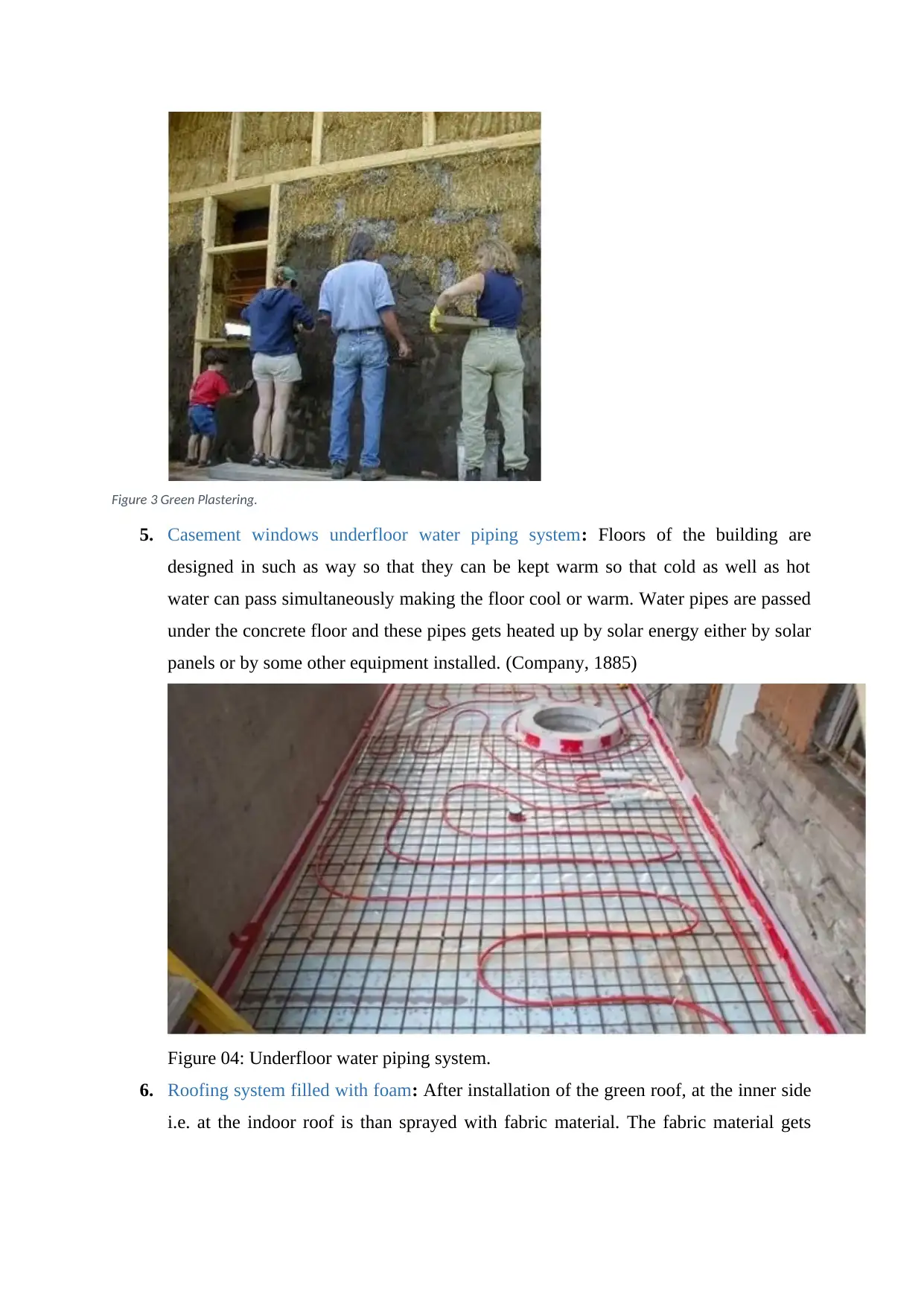
Figure 3 Green Plastering.
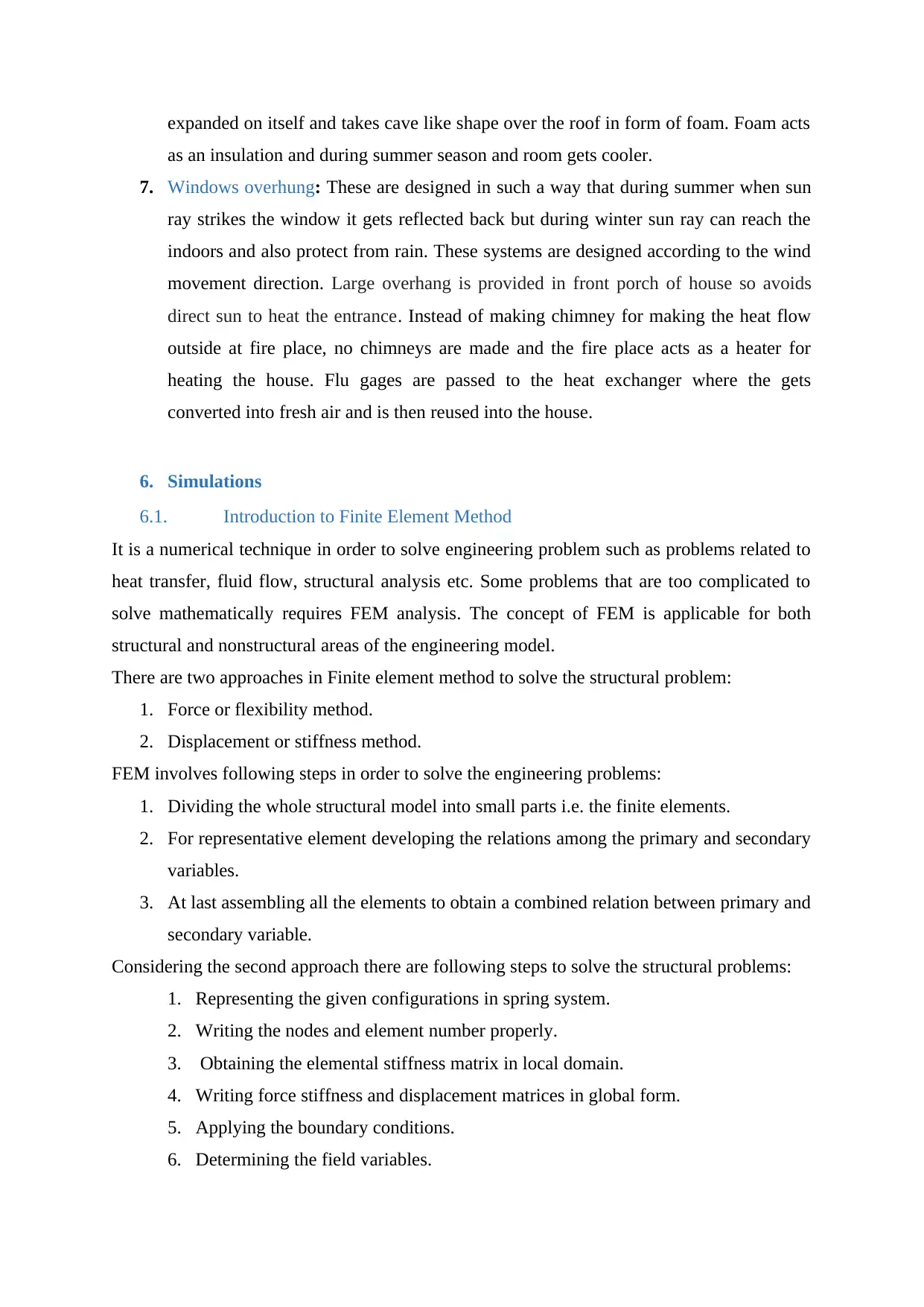
5. Casement windows underfloor water piping system: Floors of the building are
designed in such as way so that they can be kept warm so that cold as well as hot
water can pass simultaneously making the floor cool or warm. Water pipes are passed
under the concrete floor and these pipes gets heated up by solar energy either by solar
panels or by some other equipment installed. (Company, 1885)
Figure 04: Underfloor water piping system.
6. Roofing system filled with foam: After installation of the green roof, at the inner side
i.e. at the indoor roof is than sprayed with fabric material. The fabric material gets
Paraphrase This Document
Need a fresh take? Get an instant paraphrase of this document with our AI Paraphraser
expanded on itself and takes cave like shape over the roof in form of foam. Foam acts
as an insulation and during summer season and room gets cooler.
7. Windows overhung: These are designed in such a way that during summer when sun
ray strikes the window it gets reflected back but during winter sun ray can reach the
indoors and also protect from rain. These systems are designed according to the wind
movement direction. Large overhang is provided in front porch of house so avoids
direct sun to heat the entrance. Instead of making chimney for making the heat flow
outside at fire place, no chimneys are made and the fire place acts as a heater for
heating the house. Flu gages are passed to the heat exchanger where the gets
converted into fresh air and is then reused into the house.
6. Simulations
6.1. Introduction to Finite Element Method
It is a numerical technique in order to solve engineering problem such as problems related to
heat transfer, fluid flow, structural analysis etc. Some problems that are too complicated to
solve mathematically requires FEM analysis. The concept of FEM is applicable for both
structural and nonstructural areas of the engineering model.
There are two approaches in Finite element method to solve the structural problem:
1. Force or flexibility method.
2. Displacement or stiffness method.
FEM involves following steps in order to solve the engineering problems:
1. Dividing the whole structural model into small parts i.e. the finite elements.
2. For representative element developing the relations among the primary and secondary
variables.
3. At last assembling all the elements to obtain a combined relation between primary and
secondary variable.
Considering the second approach there are following steps to solve the structural problems:
1. Representing the given configurations in spring system.
2. Writing the nodes and element number properly.
3. Obtaining the elemental stiffness matrix in local domain.
4. Writing force stiffness and displacement matrices in global form.
5. Applying the boundary conditions.
6. Determining the field variables.
7. Finding the strain in the elements.
8. Finding the stress components.
9. Obtaining the reactions.
6.2. Introduction to ANSYS
ANSYS is software used to design the product and to simulate it in the computer itself and
testing the durability of the design. (F. & J., 2009)
The finite element method is an oldest method among all methods in solving the numerical
solution of partial differential equations. This method was derived by Euler in year 1768. It is
used to get numerical solutions of the differential equations by manual calculation i.e. by
hand calculation. In this method at a number of grids/elements are defined with their
respective nodal points. Each grid with the number of nodal points are use-d to describe the
fluid - flow domain. Then the concept of Taylor series expansion is applied in-order to
generate finite-difference approximation-s to the partial derivatives of the governing
equations. These derivatives are then replaced by using finite-difference approximations and
this all results in an algebraic equation for the flow solution at each of the grid point. This
method is most commonly used in structured grids since it requires a mesh having a high
degree of regularity and accuracy. From all above discussion Finite Element Method can be
summarized in three basic features:-
1. Bifurcate the whole body / structure into parts, finite element.
2. For each representative elements create the relations among secondary and primary
variable.
3. Assemble of the elements to obtain the relations in form of equation or a matrix
between the secondary and primary variables.
As per discretization is concerned the two compatibility conditions must be ensured:-
1. Compatibility of nodal displacement:- When a body is deformed without breaking, no
crack appears in stretching and particles do not penetrates each other in elements.
Such situation is called Nodal displacement compatibility. The compatibility
condition confirms that the displacement is continuous and single value function of
position.
2. Equilibrium of forces:- The equilibrium at the nodal forces must be ensured.
Although there are a numerous of commercial and research codes that are available and
they can be employed but the in finite-element method CFD application is not so much
fruitful. But apart from this there is one method which is in brief same as finite element
method and is seems fruitful and commercially uses all codes and is essentially used by
CFD. The method is called “Finite - Volume Method (FVM)”. The only differentiating
feature is that FVM uses simple piecewise polynomial functions for local elements which
tends to describe the variations of the un-known flow variables. The weighted residual
concept is introduced in order to evaluate the errors associated with the approximate
functions, which are later surely minimized. A set of non-linear algebraic equations for
the unknown terms of the approximating functions is solved, hence resulting in the flow
solution. The residual functions are solved and the flow solutions are obtained by,
Collocation method, Galerkins method, Sub-domain method, and least square method.
Spectral method
Spectral method has a same general approach as that of the finite-difference and finite-
element methods, where the unknowns of the equations that are governed are replaced with a
some short series. The difference is in only the methods of implementation. The previous two
methods uses local approximations but the spectral method implements global
approximation. That is by means of Fourier series, Legendre polynomials, for the entire flow
body / domain. The conflict between the exact solution and the approximate solution is dealt
with by the use of a weighted residuals concept similar to the finite-element method.
6.3. Simulation done by other researchers using same parameters for different
materials
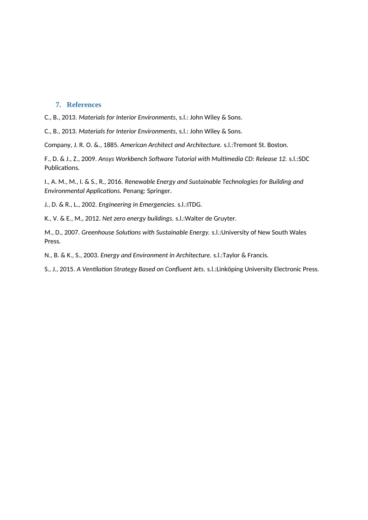
For Wall
Figure 4 concrete material
Beam/column Material
Secure Best Marks with AI Grader
Need help grading? Try our AI Grader for instant feedback on your assignments.
7. References
C., B., 2013. Materials for Interior Environments, s.l.: John Wiley & Sons.
C., B., 2013. Materials for Interior Environments, s.l.: John Wiley & Sons.
Company, J. R. O. &., 1885. American Architect and Architecture. s.l.:Tremont St. Boston.
F., D. & J., Z., 2009. Ansys Workbench Software Tutorial with Multimedia CD: Release 12. s.l.:SDC
Publications.
I., A. M., M., I. & S., R., 2016. Renewable Energy and Sustainable Technologies for Building and
Environmental Applications. Penang: Springer.
J., D. & R., L., 2002. Engineering in Emergencies. s.l.:ITDG.
K., V. & E., M., 2012. Net zero energy buildings. s.l.:Walter de Gruyter.
M., D., 2007. Greenhouse Solutions with Sustainable Energy. s.l.:University of New South Wales
Press.
N., B. & K., S., 2003. Energy and Environment in Architecture. s.l.:Taylor & Francis.
S., J., 2015. A Ventilation Strategy Based on Confluent Jets. s.l.:Linköping University Electronic Press.
C., B., 2013. Materials for Interior Environments, s.l.: John Wiley & Sons.
C., B., 2013. Materials for Interior Environments, s.l.: John Wiley & Sons.
Company, J. R. O. &., 1885. American Architect and Architecture. s.l.:Tremont St. Boston.
F., D. & J., Z., 2009. Ansys Workbench Software Tutorial with Multimedia CD: Release 12. s.l.:SDC
Publications.
I., A. M., M., I. & S., R., 2016. Renewable Energy and Sustainable Technologies for Building and
Environmental Applications. Penang: Springer.
J., D. & R., L., 2002. Engineering in Emergencies. s.l.:ITDG.
K., V. & E., M., 2012. Net zero energy buildings. s.l.:Walter de Gruyter.
M., D., 2007. Greenhouse Solutions with Sustainable Energy. s.l.:University of New South Wales
Press.
N., B. & K., S., 2003. Energy and Environment in Architecture. s.l.:Taylor & Francis.
S., J., 2015. A Ventilation Strategy Based on Confluent Jets. s.l.:Linköping University Electronic Press.
1 out of 11
Related Documents
Your All-in-One AI-Powered Toolkit for Academic Success.
+13062052269
info@desklib.com
Available 24*7 on WhatsApp / Email
![[object Object]](/_next/static/media/star-bottom.7253800d.svg)
Unlock your academic potential
© 2024 | Zucol Services PVT LTD | All rights reserved.


