3D Printing Technology for Lightweight Unmanned Aerial Vehicle
VerifiedAdded on 2023/06/12
|6
|5293
|334
Report
AI Summary
This report investigates the application of 3D printing technology for designing lightweight Unmanned Aerial Vehicle (UAV) wing structures. It addresses the need for fast adaptable UAV designs that are agile, fuel-efficient, and flexible. The research focuses on identifying an optimal truss lattice for deployable UAV wing design, considering three lattice designs: 3D Kagome structure, 3D pyramidal structure, and the hexagonal diamond structure. These designs are fabricated using an Objet 350 3D printer with Objet DurusWhite RGD430 material. The study includes compression testing to evaluate the performance of these structures, aiming to combine compliant mechanisms and deployable structures for maximizing flexibilities in UAV design and development. The paper also reviews additive manufacturing techniques, structures for high-strength lightweight materials, and provides a detailed description of the three 3D lattice structures used in the experiment.
INTERNATIONAL JOURNAL OF PRECISION ENGINEERING AND MANUFACTURING-GREEN TECHNOLOGY Vol. 1, No. 3, pp. 223-228 JULY 2014 / 223
© KSPE and Springer 2014
Application of 3D Printing Technology for D
Light-weight Unmanned Aerial Vehicle Wing St
Seung Ki Moon1, Yu En Tan1, Jihong Hwang2
, andYong-Jin Yoon1,#
1 School of Mechanical and Aerospace Engineering, NTU Additive Manufacturing Centre, Nanyang Technological University, 50 Na
2 Department of Mechanical System Design Eng., Seoul Nat’l Univ. of Sci. & Tech., 233 Gongreung-ro, Nowon-g
# Corresponding Author / E-mail: yongjiny@ntu.edu.sg, TEL: +65-6790-5033, FAX:
KEYWORDS: 3D Printing, Additive manufacturing, Deployable wing design, Light-weight structures, Un
Unmanned Aerial Vehicles (UAVs) have been developed to perform various military and civilian applications, su
attack missions, surveillance of pipelines, and interplanetary exploration. The present research is motivated by
a fast adaptable UAV design technologies for agile, fuel efficient, and flexible structures that are capable of ada
in any environments. The objective of this research is to develop adaptive design technologies by investigating
and knowledge of deployable technologies in the area of engineering design and manufacturing. More specifica
to identify one truss lattice with the optimal elastic performance for deployable UAV wing design acco
Shtrikman theoretical bounds. We propose three lattice designs - 3D Kagome structure, 3D pyramidal structure
diamond structure. The proposed lattice structure designs are fabricated using an Objet 350 3D printer while th
is a polypropylene-like photopolymer called Objet DurusWhite RGD430. Based on compression testing, the prop
design will combine the advantages of compliant mechanisms and deployable structures to maximize flexibilitie
design and development.
Manuscript received: March 21, 2014 / Revised: April 22, 2014 / Accepted: April 28, 201
1. Introduction
Unmanned Aerial Vehicles (UAVs) have been developed to perform
various military and civilian applications, such as reconnaissance,
attack missions, surveillanceof pipelines,and interplanetary
exploration.Recently,small and deployableUAVs have gained
attentiondue to a wide range of potentialapplicationswith
sophisticatedoperationsand increasedflexibilitiesfor smaller
transportationenclosuresand storage.The idea of incorporating
inflatable structures into flight has existed for a long time, but it w
only in the last few decades that inflatable wing technology
properly developed. One of the earliest successful demonstrations
the Goodyear inflatoplane developed during the 1950s. During
period, Goodyear Aerospace designed and manufactured num
aircraft prototypes equipped with inflatable components. One of th
final designs was the GA-468 Inflatoplane.1 The inflatoplane was
developed as a military rescue plane that can be dropped behind e
lines near downed pilots to help them escape. More recently, NASA
Dryden research center developed the I2000 micro UAV that
designedwith wings madeof inflatabletubessurroundedwith
crushable foam. During its test flight, the UAV was launched from
larger UAV “mother ship” at an altitude of around 300 meters and
inflatable wings deployed from a compacted state in about one-th
a second. The wings were developed by Vertigo, Inc. for the US Na
as a gun-launched observation vehicle. Compared with the inflatop
the I2000 is much smaller and has a wingspan of 1.63 m and a cho
length of 0.18 m.2 By changing the wings of a UAV from a rigi
NOMENCLATURE
σB Flexural modulus
σT Tensile strength
σY Yeild strength
σU Flexural strength
E Modulus of elasticity
H Height
∆ Change
DOI: 10.1007/s40684-014-0028-x
Paraphrase This Document
Need a fresh take? Get an instant paraphrase of this document with our AI Paraphraser
224 / JULY 2014 INTERNATIONAL JOURNAL OF PRECISION ENGINEERING AND MANUFACTURING-GREEN TECHNOLOGY Vol.
design to an inflatable one, improved portability through reduced
volume/weight ratio is one possible advantage that can be obtained. A
second possible advantage of using an inflatable wing is that the
geometry of the wing can be easily changed from, for example, the
standard wing spans to a high-aspect ratio designs to suit mission
requirements.
High-strength light-weight materials have relatively high stiffness
and yield strength that are achievable at low density. They play a
significant role in achieving fuel efficiency goals for the aerospace and
automotive industries among others.3,4 Honeycombs, foams, and truss
latticestructuresare examplesof the high-strengthlight-weight
materials. The three structures have been extensively developed and
optimizedto provide unique performancebenefitsin various
applications.5-7
Based on the results from literatures, it can be seen that 3D truss
lattices are superior to both metal foams and honeycombs in terms of
elastic modulus. Moreover, in contrast to closed cell metal foams and
honeycombs which are open only from one direction, truss lattices has
the addedadvantageof an open structurefor multi-functional
applications such as heat transfer roles. The objective of this research
is to develop adaptive design technologies by investigating current
design methods and knowledge of deployable technologies in the area
of engineeringdesignand manufacturing.More specifically,we
investigate the apparent strengths of truss lattices to identify the truss
lattice with the optimalelastic performance.We comparethe
compressive strength of three lattice structures that have high values in
elastic performance for deployable UAV wing design. We propose
three lattice designs, such as 3D Kagome structure, 3D pyramidal
structure and the hexagonal diamond structure, for compression testing.
The proposed lattice structure designs are fabricated using an Objet 350
3D printer while the materialchosenis a polypropylene-like
photopolymercalled Objet DurusWhiteRGD430. Based on the
compression testing, the proposed inflatable wing design will combine
the advantages of compliant mechanisms and deployable structures to
maximize flexibilities of movement in UAV development.
The remainder of this paper is organized as follows. Section 2
reviews related literature and background in lattice structures. Section
3 describes the proposed method for fabricating the proposed three
structures. Section 4 gives experiments for a compression test. Results,
discussion,and applicationsare describedin Section5. Closing
remarks and future work are presented in Section 6.
2. Literature Reviews and Background
2.1 Additive Manufacturing
Additive manufacturing (AM) is an umbrella term referring to a
group of technologies used for building physical models, prototypes,
patterns, tooling components, and final production parts from computer
data, three dimensional scanning systems, or video games.8 AM forms
objects layer by layer through the joining of liquid, powder, or sheet
materialsas opposedto traditionalmanufacturingtechniqueslike
machining which are subtractive in nature. AM is used to produce parts
that are difficult or impossible to fabricate using other techniques.9
Someof these technologies include stereolithography, selective
laser melting (SLM), three dimensional printing (3DP), and fus
deposition modeling (FDM). Each technology has its own stre
and weaknesses.The numberof AM technologiesis consistently
growing as awareness, acceptance and application of these techn
by designers, engineers and other professionals increase.
2.2 Structures for High-strength Light-weight Materials
A honeycomb consists of an array of hollow cells separated by t
vertical walls. The cells are normally columnar and hexagonal in sh
althoughrectangularand triangularshapesare also possible.A
common application of honeycomb is in sandwich composite
for use in aircraft structures.5
Metal foams are sponge-like materials that are manufactur
injecting inert gas into molten metal. The resulting structure is a s
filled with voids that have varying sizes and shape. If individual vo
are fully encapsulated by the solid, the structure formed is a close
metal foam. Similarly, if the voids overlap and form an interconnec
network, then the structure formed is an open cell metal foam.6
Lattice structures consist of repeating units of identical ske
structures of geometric three dimensional shapes such as a polyhe
arranged in a regular pattern. New manufacturing processes
enabled lattice structures to be more easily fabricated than before
methods devised permit entire lattice structures of unit cells
from millimetersto centimetersto be produced.7 The mechanical
properties of honeycombs, metal foams and truss lattices hav
studied extensively and numerous publications on this subject can
found. From literatures, theelastic moduli of honeycombs,metal
foams, and truss lattices are compared against the Hashin-Sh
(HS) bounds. In others, honeycombs are compared with foam
truss lattices are compared with honeycombs etc. The HS upper b
represents the maximum values for the effective elastic mod
isotropic two-phase composites for a given phase volume fraction.10 In
3D applications, rank-6 laminates are known to attain the HS boun
on the bulk and shear moduli.11 Rank laminates are obtained by a
sequentialprocesswhereat each stagethe previouslaminateis
laminated again with a single lamina in a new direction. Howev
rank laminateis a multi-length-scalestructureand thereforenot
manufacturable. Thus, there is a need to find a single-length
substitute in honeycombs, foams or truss lattices with the op
microstructure.
Among relevant research, one study indicated that closed cell fo
can be superior to honeycombs with respect to shear strength and
modulus. Also, closed cell foams provide compressive strengths w
are isotropic and yet can be comparable to the compressive stren
honeycombs in the thickness direction.12 However, the study does not
indicate whether closed cell foams attain the HS upper boun
bulk and shear moduli of an octet-truss lattice material having sing
length-scale microstructure were evaluated against the HS upper
and found to be about half the attainable values.13 The study also
compared the stiffness and strength of the octet-truss lattice to th
metal foams and found that the lattice is 3 to 10 times stiffer.
2.3 Description of 3D Lattice Structures
3D Kagome lattice structure - 2D Kagome structure originated a
traditionalbamboobasketweavepatternand was identifiedby
INTERNATIONAL JOURNAL OF PRECISION ENGINEERING AND MANUFACTURING-GREEN TECHNOLOGY Vol. 1, No. 3 JULY 2014 / 225
topology optimization as an optimal structure based on its elastic
modulusfor a rangeof fractionvolumes.13 The 3D variantwas
proposed by a recent research investigating if the superior properties
observed in the 2D variant are carried over.14 3D Kagome core panels
were found to be superior to both tetrahedral and pyramidal truss core
panels. Both analytical and empirical studies attributed the greater load
carrying capacity and lower softening rate beyond the peak load to the
3D variant’s diminished sensitivity to plastic buckling.15,16 In this
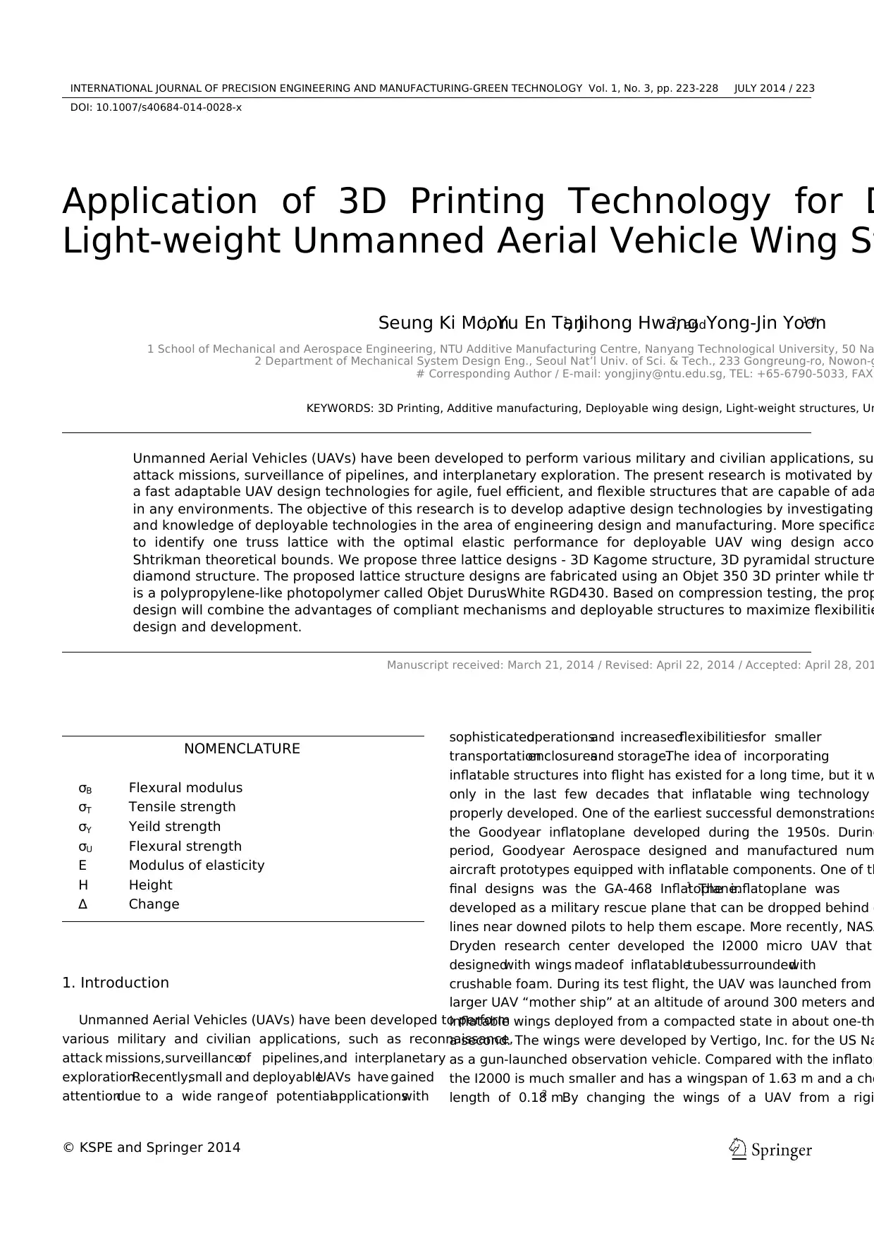
experiment, the 3D Kagome structure is tested as a truss core panel
sandwiched between two solid face sheets as shown in Fig. 1. This is
identical to the configuration used in earlier experiments.16 The 3D
Kagome structure is formed by having pairs of tetrahedrons vertically
inverted and rotationally offset from each other by 60o.
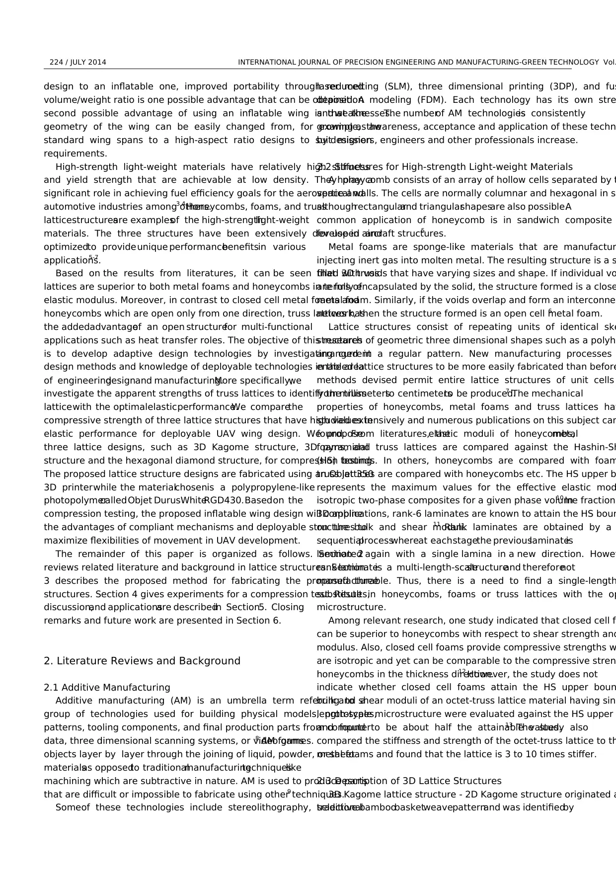
Hexagonaldiamondstructure- The hexagonaldiamondis a
hexagonal modification of the cubic diamond structure. It has been
found embedded in meteorites17 and synthesized in the laboratory using
high temperatures and pressures.18 This structure may also be present
in carbon films grown using chemical vapor deposition that is found to
contain a high density of (111) microtwins and stacking faults.
The local atomic arrangements of the hexagonal and cubic diamond
are similar. Both have covalent tetrahedral bonds and contain six-
membered rings of bonds. The main difference is the alignment of their
(111) atomic layers (each pair labeled as A, B or C). In the cubic
diamond,each successivelayer is displacedsidewaysfrom the
previous with the fourth layer returning to the same position as th
leading to a stacking sequence ABCABC…. The stacking sequence
hexagonal diamond, in contrast, is of the type ABAB….
More importantly, research has shown that the hexagonal diam
is around 58% harder than cubic diamond and is able to resist up t
GPA of indentationpressure.19 Given the uniquepropertiesof
hexagonal diamond, we are interested in evaluating the performa
this structure as a macro-sized lattice structure. The unit cell struc
of the hexagonal diamond is shown in Fig. 2.
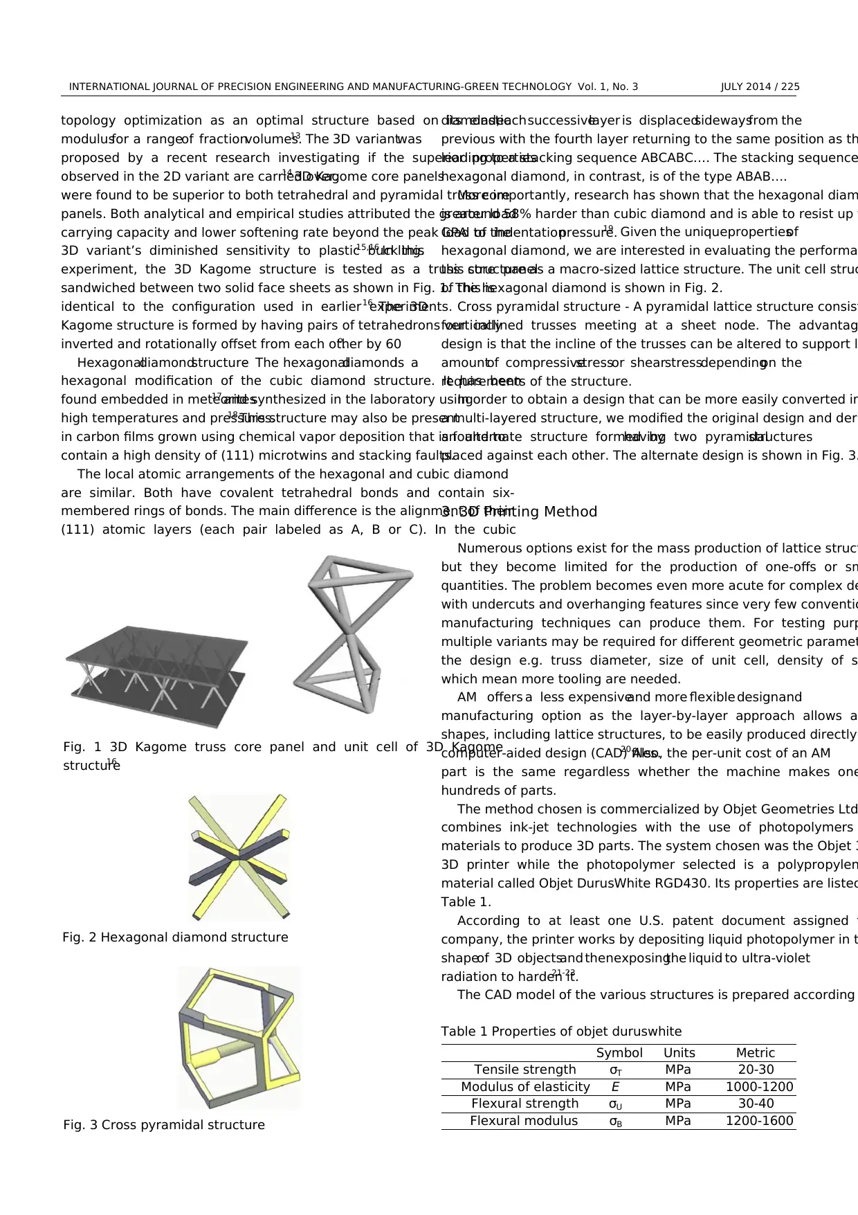
Cross pyramidal structure - A pyramidal lattice structure consist
four inclined trusses meeting at a sheet node. The advantag
design is that the incline of the trusses can be altered to support l
amountof compressivestressor shearstressdependingon the
requirements of the structure.
In order to obtain a design that can be more easily converted in
a multi-layered structure, we modified the original design and deri
an alternate structure formed byhaving two pyramidalstructures
placed against each other. The alternate design is shown in Fig. 3.
3. 3D Printing Method
Numerous options exist for the mass production of lattice struct
but they become limited for the production of one-offs or sm
quantities. The problem becomes even more acute for complex de
with undercuts and overhanging features since very few conventio
manufacturing techniques can produce them. For testing purp
multiple variants may be required for different geometric paramet
the design e.g. truss diameter, size of unit cell, density of s
which mean more tooling are needed.
AM offers a less expensiveand more flexible designand
manufacturing option as the layer-by-layer approach allows a
shapes, including lattice structures, to be easily produced directly
computer-aided design (CAD) files.20 Also, the per-unit cost of an AM
part is the same regardless whether the machine makes one
hundreds of parts.
The method chosen is commercialized by Objet Geometries Ltd
combines ink-jet technologies with the use of photopolymers
materials to produce 3D parts. The system chosen was the Objet 3
3D printer while the photopolymer selected is a polypropylen
material called Objet DurusWhite RGD430. Its properties are listed
Table 1.
According to at least one U.S. patent document assigned t
company, the printer works by depositing liquid photopolymer in t
shapeof 3D objectsand thenexposingthe liquid to ultra-violet
radiation to harden it.21-23
The CAD model of the various structures is prepared according
Fig. 1 3D Kagome truss core panel and unit cell of 3D Kagome
structure16
Fig. 2 Hexagonal diamond structure
Fig. 3 Cross pyramidal structure
Table 1 Properties of objet duruswhite
Symbol Units Metric
Tensile strength σT MPa 20-30
Modulus of elasticity E MPa 1000-1200
Flexural strength σU MPa 30-40
Flexural modulus σB MPa 1200-1600
topology optimization as an optimal structure based on its elastic
modulusfor a rangeof fractionvolumes.13 The 3D variantwas
proposed by a recent research investigating if the superior properties
observed in the 2D variant are carried over.14 3D Kagome core panels
were found to be superior to both tetrahedral and pyramidal truss core
panels. Both analytical and empirical studies attributed the greater load
carrying capacity and lower softening rate beyond the peak load to the
3D variant’s diminished sensitivity to plastic buckling.15,16 In this
experiment, the 3D Kagome structure is tested as a truss core panel
sandwiched between two solid face sheets as shown in Fig. 1. This is
identical to the configuration used in earlier experiments.16 The 3D
Kagome structure is formed by having pairs of tetrahedrons vertically
inverted and rotationally offset from each other by 60o.
Hexagonaldiamondstructure- The hexagonaldiamondis a
hexagonal modification of the cubic diamond structure. It has been
found embedded in meteorites17 and synthesized in the laboratory using
high temperatures and pressures.18 This structure may also be present
in carbon films grown using chemical vapor deposition that is found to
contain a high density of (111) microtwins and stacking faults.
The local atomic arrangements of the hexagonal and cubic diamond
are similar. Both have covalent tetrahedral bonds and contain six-
membered rings of bonds. The main difference is the alignment of their
(111) atomic layers (each pair labeled as A, B or C). In the cubic
diamond,each successivelayer is displacedsidewaysfrom the
previous with the fourth layer returning to the same position as th
leading to a stacking sequence ABCABC…. The stacking sequence
hexagonal diamond, in contrast, is of the type ABAB….
More importantly, research has shown that the hexagonal diam
is around 58% harder than cubic diamond and is able to resist up t
GPA of indentationpressure.19 Given the uniquepropertiesof
hexagonal diamond, we are interested in evaluating the performa
this structure as a macro-sized lattice structure. The unit cell struc
of the hexagonal diamond is shown in Fig. 2.
Cross pyramidal structure - A pyramidal lattice structure consist
four inclined trusses meeting at a sheet node. The advantag
design is that the incline of the trusses can be altered to support l
amountof compressivestressor shearstressdependingon the
requirements of the structure.
In order to obtain a design that can be more easily converted in
a multi-layered structure, we modified the original design and deri
an alternate structure formed byhaving two pyramidalstructures
placed against each other. The alternate design is shown in Fig. 3.
3. 3D Printing Method
Numerous options exist for the mass production of lattice struct
but they become limited for the production of one-offs or sm
quantities. The problem becomes even more acute for complex de
with undercuts and overhanging features since very few conventio
manufacturing techniques can produce them. For testing purp
multiple variants may be required for different geometric paramet
the design e.g. truss diameter, size of unit cell, density of s
which mean more tooling are needed.
AM offers a less expensiveand more flexible designand
manufacturing option as the layer-by-layer approach allows a
shapes, including lattice structures, to be easily produced directly
computer-aided design (CAD) files.20 Also, the per-unit cost of an AM
part is the same regardless whether the machine makes one
hundreds of parts.
The method chosen is commercialized by Objet Geometries Ltd
combines ink-jet technologies with the use of photopolymers
materials to produce 3D parts. The system chosen was the Objet 3
3D printer while the photopolymer selected is a polypropylen
material called Objet DurusWhite RGD430. Its properties are listed
Table 1.
According to at least one U.S. patent document assigned t
company, the printer works by depositing liquid photopolymer in t
shapeof 3D objectsand thenexposingthe liquid to ultra-violet
radiation to harden it.21-23
The CAD model of the various structures is prepared according
Fig. 1 3D Kagome truss core panel and unit cell of 3D Kagome
structure16
Fig. 2 Hexagonal diamond structure
Fig. 3 Cross pyramidal structure
Table 1 Properties of objet duruswhite
Symbol Units Metric
Tensile strength σT MPa 20-30
Modulus of elasticity E MPa 1000-1200
Flexural strength σU MPa 30-40
Flexural modulus σB MPa 1200-1600
⊘ This is a preview!⊘
Do you want full access?
Subscribe today to unlock all pages.
Trusted by 1+ million students worldwide
226 / JULY 2014 INTERNATIONAL JOURNAL OF PRECISION ENGINEERING AND MANUFACTURING-GREEN TECHNOLOGY Vol.
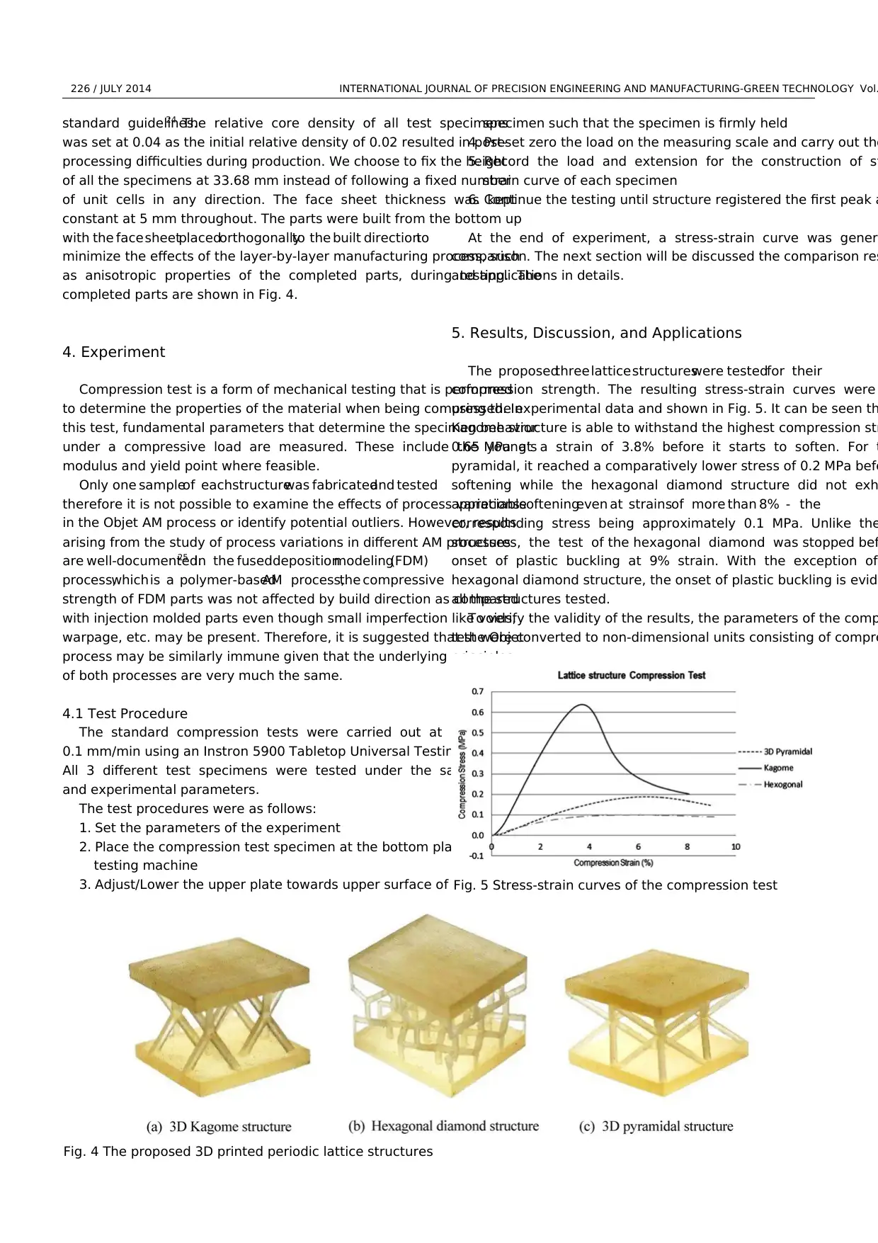
standard guidelines.24 The relative core density of all test specimens
was set at 0.04 as the initial relative density of 0.02 resulted in post-
processing difficulties during production. We choose to fix the height
of all the specimens at 33.68 mm instead of following a fixed number
of unit cells in any direction. The face sheet thickness was kept
constant at 5 mm throughout. The parts were built from the bottom up
with the face sheetplacedorthogonallyto the built directionto
minimize the effects of the layer-by-layer manufacturing process, such
as anisotropic properties of the completed parts, during testing. The
completed parts are shown in Fig. 4.
4. Experiment
Compression test is a form of mechanical testing that is performed
to determine the properties of the material when being compressed. In
this test, fundamental parameters that determine the specimen behavior
under a compressive load are measured. These include the young’s
modulus and yield point where feasible.
Only one sampleof eachstructurewas fabricatedand tested
therefore it is not possible to examine the effects of process variations
in the Objet AM process or identify potential outliers. However, results
arising from the study of process variations in different AM processes
are well-documented.25 In the fuseddepositionmodeling(FDM)
process,which is a polymer-basedAM process,the compressive
strength of FDM parts was not affected by build direction as compared
with injection molded parts even though small imperfection like voids,
warpage, etc. may be present. Therefore, it is suggested that the Objet
process may be similarly immune given that the underlying principles
of both processes are very much the same.
4.1 Test Procedure
The standard compression tests were carried out at a feed rate of
0.1 mm/min using an Instron 5900 Tabletop Universal Testing System.
All 3 different test specimens were tested under the same conditions
and experimental parameters.
The test procedures were as follows:
1. Set the parameters of the experiment
2. Place the compression test specimen at the bottom plate of the
testing machine
3. Adjust/Lower the upper plate towards upper surface of the test
specimen such that the specimen is firmly held
4. Preset zero the load on the measuring scale and carry out the
5. Record the load and extension for the construction of st
strain curve of each specimen
6. Continue the testing until structure registered the first peak a
At the end of experiment, a stress-strain curve was gener
comparison. The next section will be discussed the comparison res
and applications in details.
5. Results, Discussion, and Applications
The proposedthree lattice structureswere testedfor their
compression strength. The resulting stress-strain curves were
using the experimental data and shown in Fig. 5. It can be seen th
Kagome structure is able to withstand the highest compression str
0.65 MPa at a strain of 3.8% before it starts to soften. For t
pyramidal, it reached a comparatively lower stress of 0.2 MPa befo
softening while the hexagonal diamond structure did not exh
appreciablesofteningeven at strainsof more than 8% - the
corresponding stress being approximately 0.1 MPa. Unlike the
structures, the test of the hexagonal diamond was stopped bef
onset of plastic buckling at 9% strain. With the exception of
hexagonal diamond structure, the onset of plastic buckling is evide
all the structures tested.
To verify the validity of the results, the parameters of the comp
test were converted to non-dimensional units consisting of compre
Fig. 4 The proposed 3D printed periodic lattice structures
Fig. 5 Stress-strain curves of the compression test
Paraphrase This Document
Need a fresh take? Get an instant paraphrase of this document with our AI Paraphraser
INTERNATIONAL JOURNAL OF PRECISION ENGINEERING AND MANUFACTURING-GREEN TECHNOLOGY Vol. 1, No. 3 JULY 2014 / 227
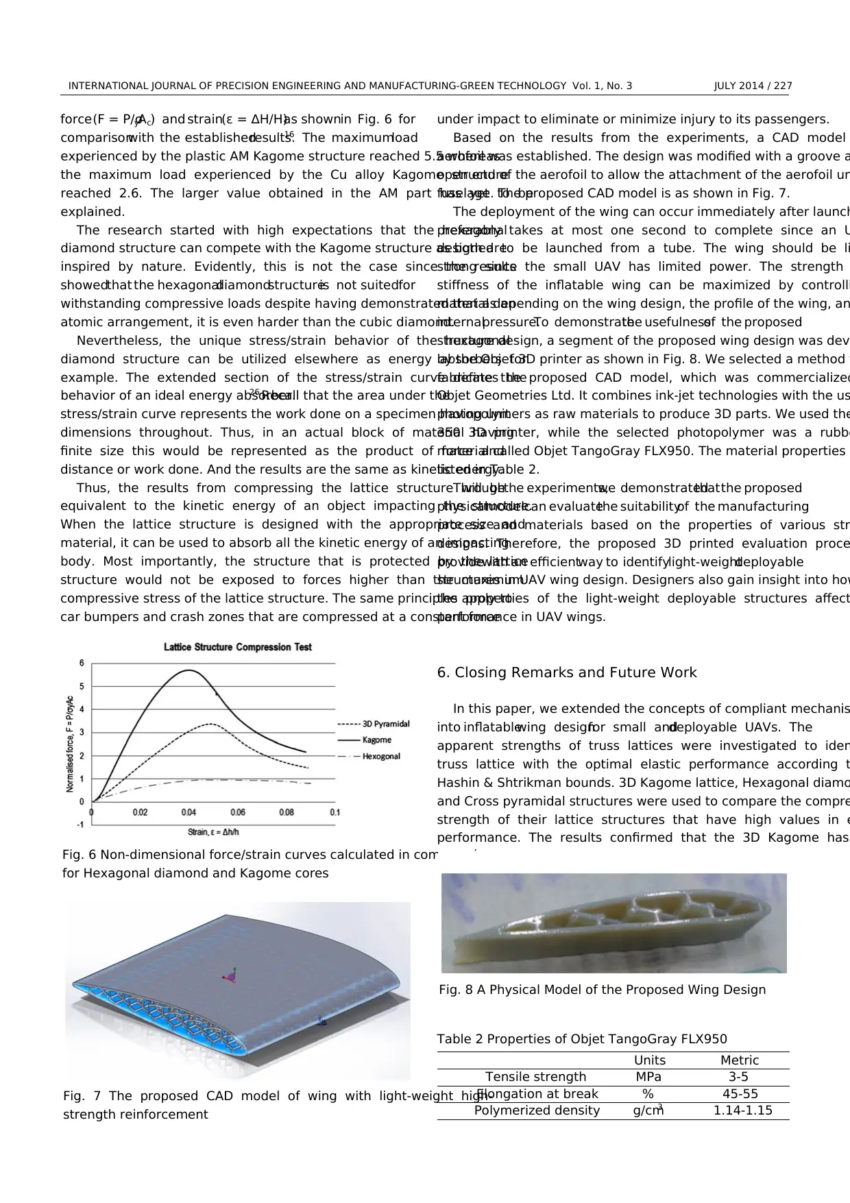
force (F = P/σyAc) and strain(ε = ∆H/H)as shownin Fig. 6 for
comparisonwith the establishedresults.16 The maximumload
experienced by the plastic AM Kagome structure reached 5.5 whereas
the maximum load experienced by the Cu alloy Kagome structure
reached 2.6. The larger value obtained in the AM part has yet to be
explained.
The research started with high expectations that the hexagonal
diamond structure can compete with the Kagome structure as both are
inspired by nature. Evidently, this is not the case since the results
showedthat the hexagonaldiamondstructureis not suitedfor
withstanding compressive loads despite having demonstrated that as an
atomic arrangement, it is even harder than the cubic diamond.
Nevertheless, the unique stress/strain behavior of the hexagonal
diamond structure can be utilized elsewhere as energy absorbers for
example. The extended section of the stress/strain curve defines the
behavior of an ideal energy absorber.26 Recall that the area under the
stress/strain curve represents the work done on a specimen having unit
dimensions throughout. Thus, in an actual block of material having
finite size this would be represented as the product of force and
distance or work done. And the results are the same as kinetic energy.
Thus, the results from compressing the lattice structure will be
equivalent to the kinetic energy of an object impacting the structure.
When the lattice structure is designed with the appropriate size and
material, it can be used to absorb all the kinetic energy of an impacting
body. Most importantly, the structure that is protected by the lattice
structure would not be exposed to forces higher than the maximum
compressive stress of the lattice structure. The same principles apply to
car bumpers and crash zones that are compressed at a constant force
under impact to eliminate or minimize injury to its passengers.
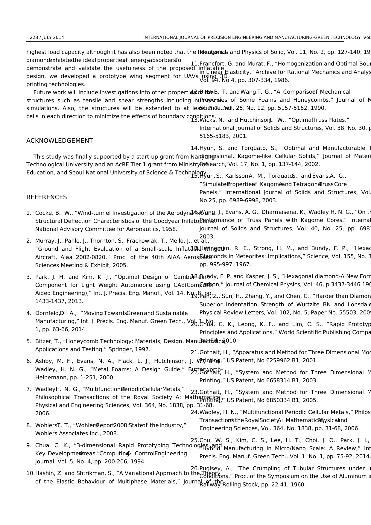
Based on the results from the experiments, a CAD model
aerofoil was established. The design was modified with a groove a
open end of the aerofoil to allow the attachment of the aerofoil un
fuselage. The proposed CAD model is as shown in Fig. 7.
The deployment of the wing can occur immediately after launch
preferably takes at most one second to complete since an U
designed to be launched from a tube. The wing should be li
strong since the small UAV has limited power. The strength
stiffness of the inflatable wing can be maximized by controlli
material depending on the wing design, the profile of the wing, an
internalpressure.To demonstratethe usefulnessof the proposed
structure design, a segment of the proposed wing design was deve
by the Objet 3D printer as shown in Fig. 8. We selected a method t
fabricate the proposed CAD model, which was commercialized
Objet Geometries Ltd. It combines ink-jet technologies with the us
photopolymers as raw materials to produce 3D parts. We used the
350 3D printer, while the selected photopolymer was a rubbe
material called Objet TangoGray FLX950. The material properties a
listed in Table 2.
Throughthe experiments,we demonstratedthat the proposed
physicalmodelcan evaluatethe suitabilityof the manufacturing
process and materials based on the properties of various str
designs. Therefore, the proposed 3D printed evaluation proce
providewith an efficientway to identifylight-weightdeployable
structures in UAV wing design. Designers also gain insight into how
the properties of the light-weight deployable structures affect
performance in UAV wings.
6. Closing Remarks and Future Work
In this paper, we extended the concepts of compliant mechanis
into inflatablewing designfor small anddeployable UAVs. The
apparent strengths of truss lattices were investigated to iden
truss lattice with the optimal elastic performance according t
Hashin & Shtrikman bounds. 3D Kagome lattice, Hexagonal diamo
and Cross pyramidal structures were used to compare the compre
strength of their lattice structures that have high values in e
performance. The results confirmed that the 3D Kagome has
Fig. 6 Non-dimensional force/strain curves calculated in compression
for Hexagonal diamond and Kagome cores
Fig. 7 The proposed CAD model of wing with light-weight high-
strength reinforcement
Table 2 Properties of Objet TangoGray FLX950
Units Metric
Tensile strength MPa 3-5
Elongation at break % 45-55
Polymerized density g/cm3 1.14-1.15
Fig. 8 A Physical Model of the Proposed Wing Design
force (F = P/σyAc) and strain(ε = ∆H/H)as shownin Fig. 6 for
comparisonwith the establishedresults.16 The maximumload
experienced by the plastic AM Kagome structure reached 5.5 whereas
the maximum load experienced by the Cu alloy Kagome structure
reached 2.6. The larger value obtained in the AM part has yet to be
explained.
The research started with high expectations that the hexagonal
diamond structure can compete with the Kagome structure as both are
inspired by nature. Evidently, this is not the case since the results
showedthat the hexagonaldiamondstructureis not suitedfor
withstanding compressive loads despite having demonstrated that as an
atomic arrangement, it is even harder than the cubic diamond.
Nevertheless, the unique stress/strain behavior of the hexagonal
diamond structure can be utilized elsewhere as energy absorbers for
example. The extended section of the stress/strain curve defines the
behavior of an ideal energy absorber.26 Recall that the area under the
stress/strain curve represents the work done on a specimen having unit
dimensions throughout. Thus, in an actual block of material having
finite size this would be represented as the product of force and
distance or work done. And the results are the same as kinetic energy.
Thus, the results from compressing the lattice structure will be
equivalent to the kinetic energy of an object impacting the structure.
When the lattice structure is designed with the appropriate size and
material, it can be used to absorb all the kinetic energy of an impacting
body. Most importantly, the structure that is protected by the lattice
structure would not be exposed to forces higher than the maximum
compressive stress of the lattice structure. The same principles apply to
car bumpers and crash zones that are compressed at a constant force
under impact to eliminate or minimize injury to its passengers.
Based on the results from the experiments, a CAD model
aerofoil was established. The design was modified with a groove a
open end of the aerofoil to allow the attachment of the aerofoil un
fuselage. The proposed CAD model is as shown in Fig. 7.
The deployment of the wing can occur immediately after launch
preferably takes at most one second to complete since an U
designed to be launched from a tube. The wing should be li
strong since the small UAV has limited power. The strength
stiffness of the inflatable wing can be maximized by controlli
material depending on the wing design, the profile of the wing, an
internalpressure.To demonstratethe usefulnessof the proposed
structure design, a segment of the proposed wing design was deve
by the Objet 3D printer as shown in Fig. 8. We selected a method t
fabricate the proposed CAD model, which was commercialized
Objet Geometries Ltd. It combines ink-jet technologies with the us
photopolymers as raw materials to produce 3D parts. We used the
350 3D printer, while the selected photopolymer was a rubbe
material called Objet TangoGray FLX950. The material properties a
listed in Table 2.
Throughthe experiments,we demonstratedthat the proposed
physicalmodelcan evaluatethe suitabilityof the manufacturing
process and materials based on the properties of various str
designs. Therefore, the proposed 3D printed evaluation proce
providewith an efficientway to identifylight-weightdeployable
structures in UAV wing design. Designers also gain insight into how
the properties of the light-weight deployable structures affect
performance in UAV wings.
6. Closing Remarks and Future Work
In this paper, we extended the concepts of compliant mechanis
into inflatablewing designfor small anddeployable UAVs. The
apparent strengths of truss lattices were investigated to iden
truss lattice with the optimal elastic performance according t
Hashin & Shtrikman bounds. 3D Kagome lattice, Hexagonal diamo
and Cross pyramidal structures were used to compare the compre
strength of their lattice structures that have high values in e
performance. The results confirmed that the 3D Kagome has
Fig. 6 Non-dimensional force/strain curves calculated in compression
for Hexagonal diamond and Kagome cores
Fig. 7 The proposed CAD model of wing with light-weight high-
strength reinforcement
Table 2 Properties of Objet TangoGray FLX950
Units Metric
Tensile strength MPa 3-5
Elongation at break % 45-55
Polymerized density g/cm3 1.14-1.15
Fig. 8 A Physical Model of the Proposed Wing Design
228 / JULY 2014 INTERNATIONAL JOURNAL OF PRECISION ENGINEERING AND MANUFACTURING-GREEN TECHNOLOGY Vol.
highest load capacity although it has also been noted that the hexagonal
diamondexhibitedthe ideal propertiesof energyabsorbers.To
demonstrate and validate the usefulness of the proposed inflatable
design, we developed a prototype wing segment for UAVs using 3D
printing technologies.
Future work will include investigations into other properties of the
structures such as tensile and shear strengths including numerical
simulations. Also, the structures will be extended to at least 5-7 unit
cells in each direction to minimize the effects of boundary conditions.
ACKNOWLEDGEMENT
This study was finally supported by a start-up grant from Nanyang
Technological University and an AcRF Tier 1 grant from Ministry of
Education, and Seoul National University of Science & Technology
REFERENCES
1. Cocke, B. W., “Wind-tunnel Investigation of the Aerodynamic and
Structural Deflection Characteristics of the Goodyear Inflatoplane,”
National Advisory Committee for Aeronautics, 1958.
2. Murray, J., Pahle, J., Thornton, S., Frackowiak, T., Mello, J., et al.,
“Ground and Flight Evaluation of a Small-scale Inflatable-Winged
Aircraft, Aiaa 2002-0820,” Proc. of the 40th AIAA Aerospace
Sciences Meeting & Exhibit, 2005.
3. Park, J. H. and Kim, K. J., “Optimal Design of Camber Link
Component for Light Weight Automobile using CAE(Computer
Aided Engineering),” Int. J. Precis. Eng. Manuf., Vol. 14, No. 8, pp.
1433-1437, 2013.
4. Dornfeld,D. A., “Moving TowardsGreen and Sustainable
Manufacturing,” Int. J. Precis. Eng. Manuf. Green Tech., Vol. 1, No.
1, pp. 63-66, 2014.
5. Bitzer, T., “Honeycomb Technology: Materials, Design, Manufacturing,
Applications and Testing,” Springer, 1997.
6. Ashby, M. F., Evans, N. A., Flack, L. J., Hutchinson, J. W., and
Wadley, H. N. G., “Metal Foams: A Design Guide,” Butterworth-
Heinemann, pp. 1-251, 2000.
7. Wadley,H. N. G., “MultifunctionalPeriodicCellularMetals,”
Philosophical Transactions of the Royal Society A: Mathematical,
Physical and Engineering Sciences, Vol. 364, No. 1838, pp. 31-68,
2006.
8. Wohlers,T. T., “WohlersReport2008:Stateof the Industry,”
Wohlers Associates Inc., 2008.
9. Chua, C. K., “3-dimensional Rapid Prototyping Technologies and
Key DevelopmentAreas,”Computing& ControlEngineering
Journal, Vol. 5, No. 4, pp. 200-206, 1994.
10.Hashin, Z. and Shtrikman, S., “A Variational Approach to the Theory
of the Elastic Behaviour of Multiphase Materials,” Journal of the
Mechanics and Physics of Solid, Vol. 11, No. 2, pp. 127-140, 196
11.Francfort, G. and Murat, F., “Homogenization and Optimal Boun
in Linear Elasticity,” Archive for Rational Mechanics and Analys
Vol. 94, No.4, pp. 307-334, 1986.
12.Bhat,B. T. and Wang,T. G., “A Comparisonof Mechanical
Properties of Some Foams and Honeycombs,” Journal of M
Science, Vol. 25, No. 12, pp. 5157-5162, 1990.
13.Wicks, N. and Hutchinson,J. W., “OptimalTruss Plates,”
International Journal of Solids and Structures, Vol. 38, No. 30, p
5165-5183, 2001.
14.Hyun, S. and Torquato, S., “Optimal and Manufacturable T
dimensional, Kagome-like Cellular Solids,” Journal of Materi
Research, Vol. 17, No. 1, pp. 137-144, 2002.
15.Hyun, S., Karlsson,A. M., Torquato,S., and Evans,A. G.,
“SimulatedPropertiesof Kagoméand TetragonalTruss Core
Panels,” International Journal of Solids and Structures, Vol.
No.25, pp. 6989-6998, 2003.
16.Wang, J., Evans, A. G., Dharmasena, K., Wadley H. N. G., “On th
Performance of Truss Panels with Kagome Cores,” Internat
Journal of Solids and Structures, Vol. 40, No. 25, pp. 6981
2003.
17.Hanneman, R. E., Strong, H. M., and Bundy, F. P., “Hexag
Diamonds in Meteorites: Implications,” Science, Vol. 155, No. 3
pp. 995-997, 1967.
18.Bundy, F. P. and Kasper, J. S., “Hexagonal diamond-A New Form
Carbon,” Journal of Chemical Physics, Vol. 46, p.3437-3446 196
19.Pan, Z., Sun, H., Zhang, Y., and Chen, C., “Harder than Diamon
Superior Indentation Strength of Wurtzite BN and Lonsdale
Physical Review Letters, Vol. 102, No. 5, Paper No. 55503, 2009
20.Chua, C. K., Leong, K. F., and Lim, C. S., “Rapid Prototyp
Principles and Applications,” World Scientific Publishing Compa
3rd Ed., 2010.
21.Gothait, H., “Apparatus and Method for Three Dimensional Mod
Printing,” US Patent, No 6259962 B1, 2001.
22.Gothait, H., “System and Method for Three Dimensional M
Printing,” US Patent, No 6658314 B1, 2003.
23.Gothait, H., “System and Method for Three Dimensional M
Printing,” US Patent, No 6850334 B1, 2005.
24.Wadley, H. N., “Multifunctional Periodic Cellular Metals,” Philoso
Transactionsof the RoyalSocietyA: Mathematical,Physicaland
Engineering Sciences, Vol. 364, No. 1838, pp. 31-68, 2006.
25.Chu, W. S., Kim, C. S., Lee, H. T., Choi, J. O., Park, J. I.,
“Hybrid Manufacturing in Micro/Nano Scale: A Review,” Int
Precis. Eng. Manuf. Green Tech., Vol. 1, No. 1, pp. 75-92, 2014.
26.Puglsey, A., “The Crumpling of Tubular Structures under Im
Conditions,” Proc. of the Symposium on the Use of Aluminum in
Railway Rolling Stock, pp. 22-41, 1960.
⊘ This is a preview!⊘
Do you want full access?
Subscribe today to unlock all pages.
Trusted by 1+ million students worldwide
1 out of 6

Your All-in-One AI-Powered Toolkit for Academic Success.
+13062052269
info@desklib.com
Available 24*7 on WhatsApp / Email
![[object Object]](/_next/static/media/star-bottom.7253800d.svg)
Unlock your academic potential
Copyright © 2020–2026 A2Z Services. All Rights Reserved. Developed and managed by ZUCOL.