Fundamentals of Computing 4CS015 Workshop 5 Assignment Submission

Verified

Added on  2020/04/21

|4
|606
|1175
Homework Assignment
AI Summary
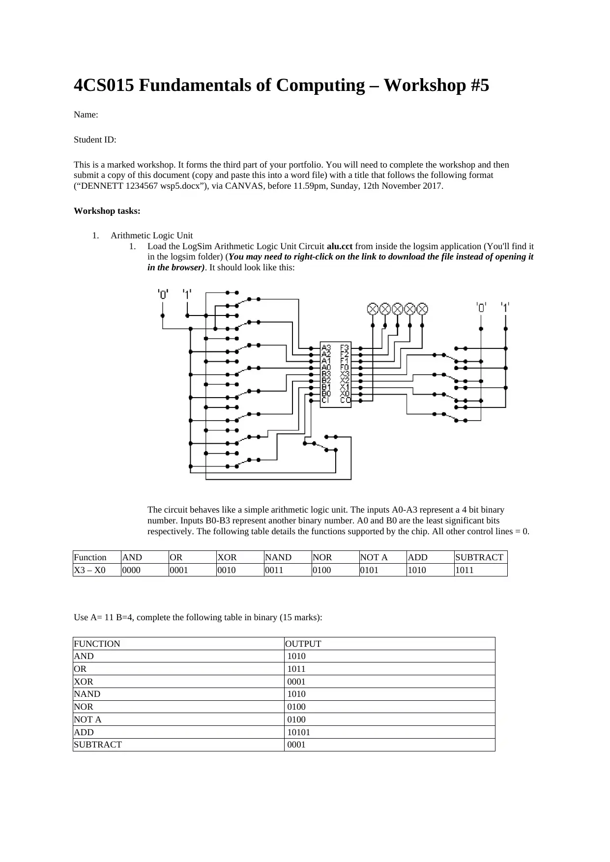
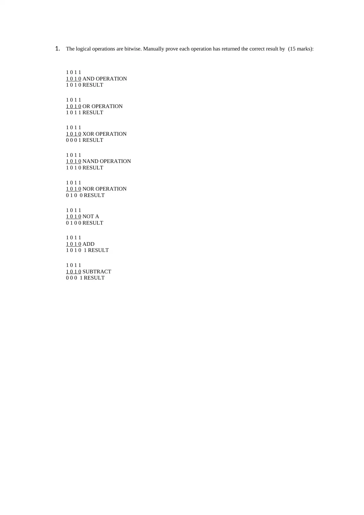
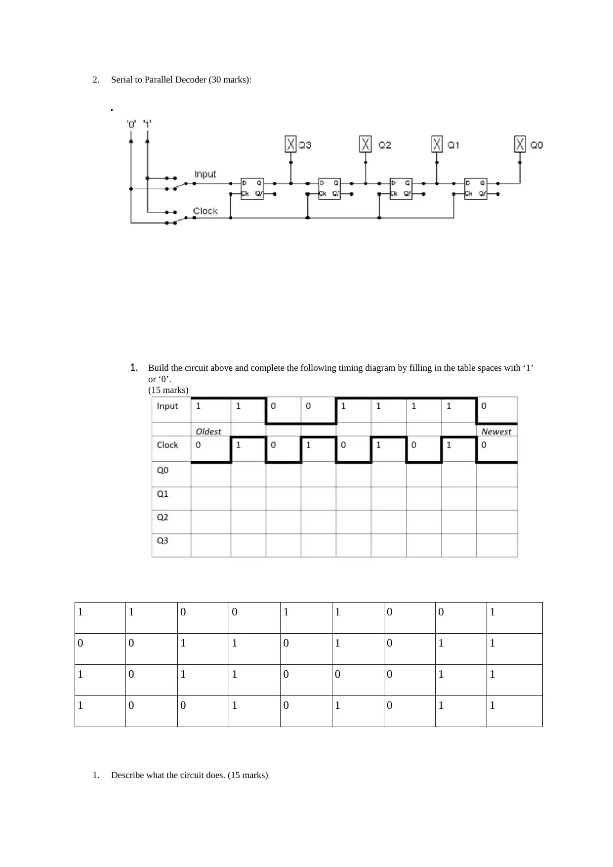
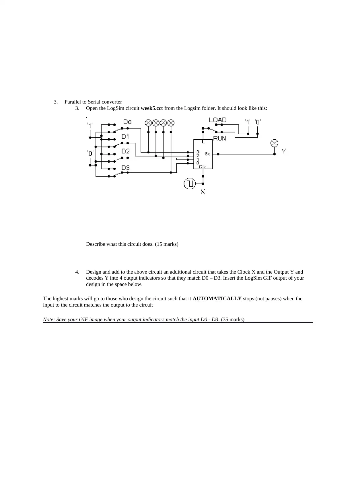
This document presents a completed assignment for a Fundamentals of Computing workshop (4CS015). The assignment focuses on understanding and implementing digital logic circuits. The first section involves working with an Arithmetic Logic Unit (ALU) in LogSim, requiring the student to determine outputs for various logical and arithmetic operations given specific binary inputs. The student is then asked to manually prove each operation's result. The second part of the assignment involves building and analyzing a serial-to-parallel decoder circuit, completing a timing diagram, and describing the circuit's function. The final section tasks the student with analyzing a parallel-to-serial converter circuit and designing an additional circuit that decodes the output to match the input indicators, with the added requirement that the circuit automatically stops when the input and output match. This workshop emphasizes practical application of digital logic concepts and circuit design using the LogSim software.
Document Page
4CS015 Fundamentals of Computing – Workshop #5
Name:
Student ID:
This is a marked workshop. It forms the third part of your portfolio. You will need to complete the workshop and then
submit a copy of this document (copy and paste this into a word file) with a title that follows the following format
(“DENNETT 1234567 wsp5.docx”), via CANVAS, before 11.59pm, Sunday, 12th November 2017.
Workshop tasks:
1. Arithmetic Logic Unit
1. Load the LogSim Arithmetic Logic Unit Circuit alu.cct from inside the logsim application (You'll find it
in the logsim folder) (You may need to right-click on the link to download the file instead of opening it
in the browser). It should look like this:
The circuit behaves like a simple arithmetic logic unit. The inputs A0-A3 represent a 4 bit binary
number. Inputs B0-B3 represent another binary number. A0 and B0 are the least significant bits
respectively. The following table details the functions supported by the chip. All other control lines = 0.
Function AND OR XOR NAND NOR NOT A ADD SUBTRACT
X3 – X0 0000 0001 0010 0011 0100 0101 1010 1011
Use A= 11 B=4, complete the following table in binary (15 marks):
FUNCTION OUTPUT
AND 1010
OR 1011
XOR 0001
NAND 1010
NOR 0100
NOT A 0100
ADD 10101
SUBTRACT 0001
tabler-icon-diamond-filled.svg

Paraphrase This Document

Need a fresh take? Get an instant paraphrase of this document with our AI Paraphraser
Document Page
1. The logical operations are bitwise. Manually prove each operation has returned the correct result by (15 marks):
1 0 1 1
1 0 1 0 AND OPERATION
1 0 1 0 RESULT
1 0 1 1
1 0 1 0 OR OPERATION
1 0 1 1 RESULT
1 0 1 1
1 0 1 0 XOR OPERATION
0 0 0 1 RESULT
1 0 1 1
1 0 1 0 NAND OPERATION
1 0 1 0 RESULT
1 0 1 1
1 0 1 0 NOR OPERATION
0 1 0 0 RESULT
1 0 1 1
1 0 1 0 NOT A
0 1 0 0 RESULT
1 0 1 1
1 0 1 0 ADD
1 0 1 0 1 RESULT
1 0 1 1
1 0 1 0 SUBTRACT
0 0 0 1 RESULT
Document Page
2. Serial to Parallel Decoder (30 marks):
1. Build the circuit above and complete the following timing diagram by filling in the table spaces with ‘1’
or ‘0’.
(15 marks)
1 1 0 0 1 1 0 0 1
0 0 1 1 0 1 0 1 1
1 0 1 1 0 0 0 1 1
1 0 0 1 0 1 0 1 1
1. Describe what the circuit does. (15 marks)
Document Page
3. Parallel to Serial converter
3. Open the LogSim circuit week5.cct from the Logsim folder. It should look like this:
Describe what this circuit does. (15 marks)
4. Design and add to the above circuit an additional circuit that takes the Clock X and the Output Y and
decodes Y into 4 output indicators so that they match D0 – D3. Insert the LogSim GIF output of your
design in the space below.
The highest marks will go to those who design the circuit such that it AUTOMATICALLY stops (not pauses) when the
input to the circuit matches the output to the circuit
Note: Save your GIF image when your output indicators match the input D0 - D3. (35 marks)
chevron_up_icon
1 out of 4
circle_padding
hide_on_mobile
zoom_out_icon
[object Object]