5ENT1013 Dynamics Coursework: University of Hertfordshire - Solution

Verified

Added on  2023/06/11

|8
|1417
|74
Homework Assignment
AI Summary
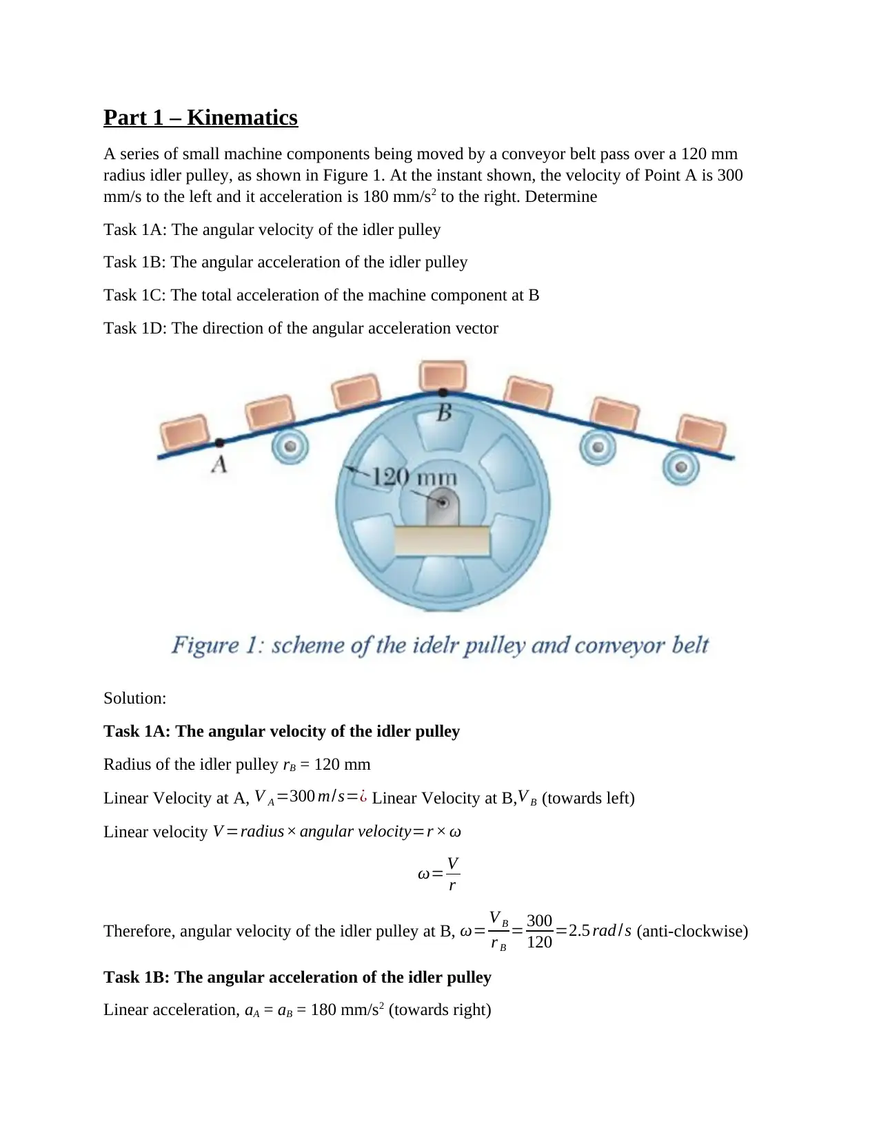
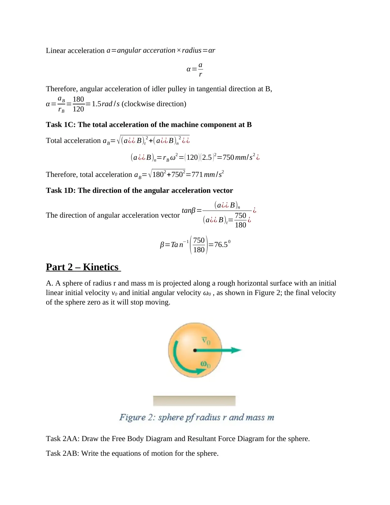
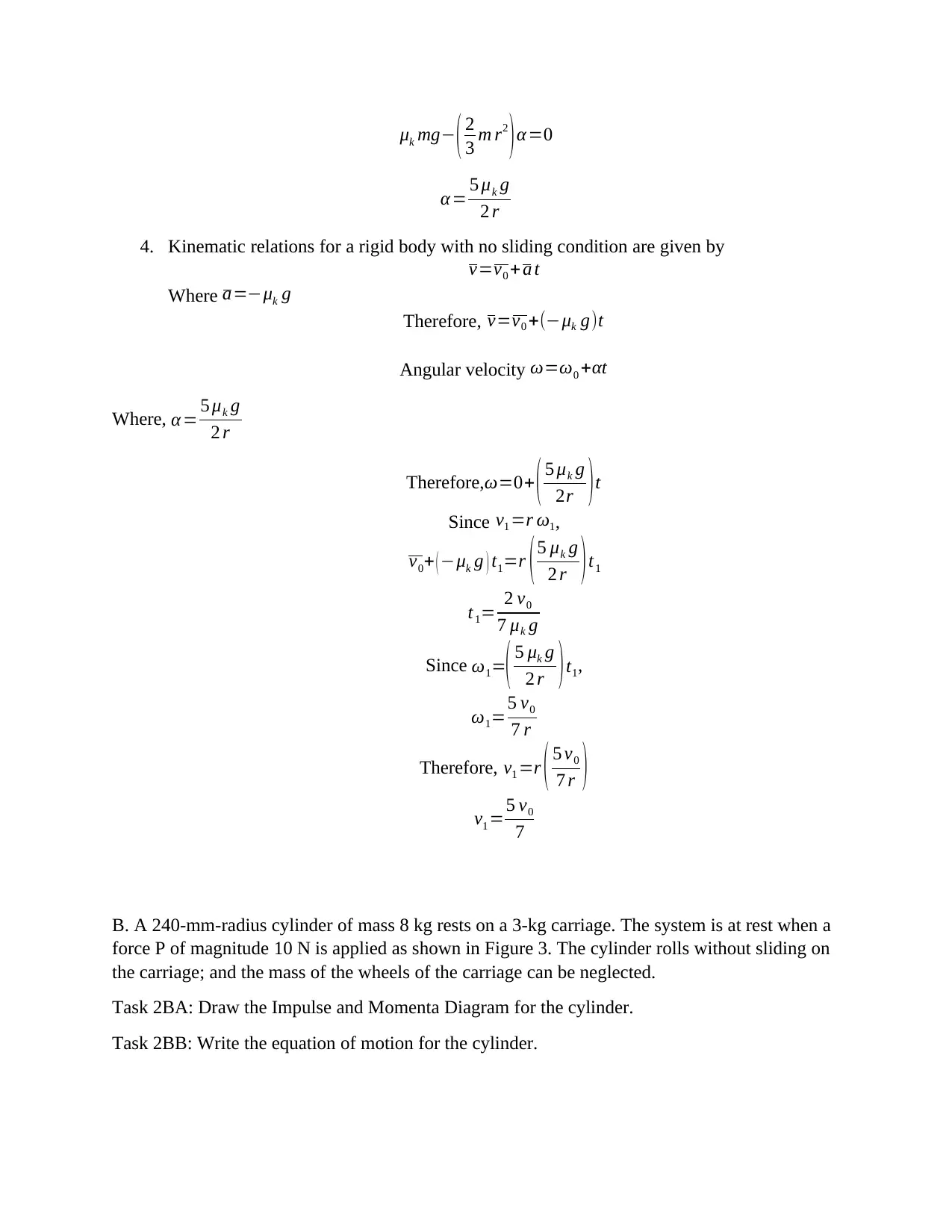
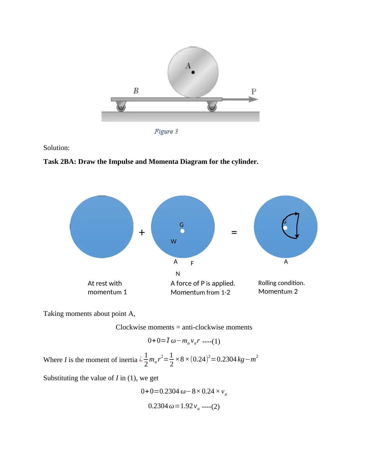
This assignment solution covers three main areas of dynamics: kinematics, kinetics, and vibrations. The kinematics section focuses on calculating angular velocity and acceleration of an idler pulley, along with the total acceleration of a machine component. The kinetics section includes free body diagrams and equations of motion for a sphere on a rough surface, as well as the analysis of a cylinder resting on a carriage with an applied force. Finally, the vibrations section derives a differential equation for a damped angular oscillation system and determines the undamped natural frequency, damping ratio, and damped natural frequency. The University of Hertfordshire's Dynamics coursework 5ENT1013 is thoroughly addressed.
tabler-icon-diamond-filled.svg

Contribute Materials

Your contribution can guide someone’s learning journey. Share your documents today.
Document Page
Part 1 – Kinematics
A series of small machine components being moved by a conveyor belt pass over a 120 mm
radius idler pulley, as shown in Figure 1. At the instant shown, the velocity of Point A is 300
mm/s to the left and it acceleration is 180 mm/s2 to the right. Determine
Task 1A: The angular velocity of the idler pulley
Task 1B: The angular acceleration of the idler pulley
Task 1C: The total acceleration of the machine component at B
Task 1D: The direction of the angular acceleration vector
Solution:
Task 1A: The angular velocity of the idler pulley
Radius of the idler pulley rB = 120 mm
Linear Velocity at A, V A =300 m/s=¿ Linear Velocity at B,V B (towards left)
Linear velocity V =radius× angular velocity=r × ω
ω= V
r
Therefore, angular velocity of the idler pulley at B, ω= V B
r B
= 300
120 =2.5 rad /s (anti-clockwise)
Task 1B: The angular acceleration of the idler pulley
Linear acceleration, aA = aB = 180 mm/s2 (towards right)
tabler-icon-diamond-filled.svg

Secure Best Marks with AI Grader

Need help grading? Try our AI Grader for instant feedback on your assignments.
Document Page
Linear acceleration a=angular acceration ×radius=αr
α= a
r
Therefore, angular acceleration of idler pulley in tangential direction at B,
α = aB
rB
=180
120 =1.5rad /s (clockwise direction)
Task 1C: The total acceleration of the machine component at B
Total acceleration aB= (a¿¿ B)t
2 +( a¿¿ B)n
2 ¿ ¿
(a ¿¿ B)n=rB ω2 = ( 120 ) ( 2.5 )2=750 mm/s2 ¿
Therefore, total acceleration aB= 1802 +7502=771 mm /s2
Task 1D: The direction of the angular acceleration vector
The direction of angular acceleration vector tanβ = (a¿¿ B)n
(a¿¿ B)t= 750
180 ¿
¿
β=Ta n1
( 750
180 )=76.50
Part 2 – Kinetics
A. A sphere of radius r and mass m is projected along a rough horizontal surface with an initial
linear initial velocity v0 and initial angular velocity ω0 , as shown in Figure 2; the final velocity
of the sphere zero as it will stop moving.
Task 2AA: Draw the Free Body Diagram and Resultant Force Diagram for the sphere.
Task 2AB: Write the equations of motion for the sphere.
Document Page
G
W
N
= G
r
Solution:
Task 2AA: Draw the Free Body Diagram and Resultant Force Diagram for the sphere.
Step 1:
Free body diagram:
Fig. 1.1 Free-body-diagram
Task 2AB: Write the equations of motion for the sphere.
Step 2:
Solve the equilibrium equations with the following conventions:
Rotation: Clockwise +ve Forces: Towards right +ve Upward +ve
Anti-clockwise −ve Towards left −ve Downward −ve
1. Algebraic sum of horizontal forces F x=0
m a=μk mg
a=μk g
2. Algebraic sum of vertical forces F y=0
NW =0
Nmg=0
N=mg
3. Algebraic sum of all the moments M G =0
FrI α=0
Document Page
μk mg ( 2
3 m r2
)α=0
α= 5 μk g
2 r
4. Kinematic relations for a rigid body with no sliding condition are given by
v=v0 +a t
Where a=μk g
Therefore, v=v0 +(μk g)t
Angular velocity ω=ω0 +αt
Where, α= 5 μk g
2 r
Therefore,ω=0+ ( 5 μk g
2r )t
Since v1 =r ω1,
v0+ ( μk g ) t1=r ( 5 μk g
2 r ) t1
t1= 2 v0
7 μk g
Since ω1=( 5 μk g
2 r )t1,
ω1=5 v0
7 r
Therefore, v1 =r ( 5 v0
7 r )
v1 =5 v0
7
B. A 240-mm-radius cylinder of mass 8 kg rests on a 3-kg carriage. The system is at rest when a
force P of magnitude 10 N is applied as shown in Figure 3. The cylinder rolls without sliding on
the carriage; and the mass of the wheels of the carriage can be neglected.
Task 2BA: Draw the Impulse and Momenta Diagram for the cylinder.
Task 2BB: Write the equation of motion for the cylinder.
tabler-icon-diamond-filled.svg

Secure Best Marks with AI Grader

Need help grading? Try our AI Grader for instant feedback on your assignments.
Document Page
At rest with
momentum 1
A force of P is applied.
Momentum from 1-2
Rolling condition.
Momentum 2
G
W
FA
=
G
r+
A
N
Solution:
Task 2BA: Draw the Impulse and Momenta Diagram for the cylinder.
Taking moments about point A,
Clockwise moments = anti-clockwise moments
0+0=I ωma va r ----(1)
Where I is the moment of inertia ¿ 1
2 ma r2=1
2 ×8 ×(0.24)2=0.2304 kgm2
Substituting the value of I in (1), we get
0+ 0=0.2304 ω8× 0.24 × va
0.2304 ω=1.92 va ----(2)
Document Page
A force of P is applied for
1.2 sec. Impulse from 1-2
G
W
=
G
r+
At rest with
momentum 1
Rolling condition.
Momentum 2
APt
Resolving the components along horizontal direction, we get
0+ Pt =ma va +mb vb
0+10 ×1.2=8 va +3 vb ----(3)
Task 2BB: Write the equation of motion for the cylinder.
For a rigid body rolling without slipping, velocity va=vb
va=vb0.24 ω ----(4)
To get the values of velocities, solve equations (2), (3), and (4).
Therefore, angular velocity ω=5.68 rad /s
Velocity of the cylinder va=0.706 m/s
Velocity of the carriage vb=2.12 m/s
Part 3 – Vibrations
In the system shown in Figure 4 a mass m is attached to a light rigid arm OA freely pivoted at O,
and makes small damped angular oscillations in the horizontal plane when displaced with a small
angular displacement θ and then released.
Task 3A: Show that the motion can be described by the following differential equation:
¨θ+ 4 c
9 m ˙θ+ 16 k
9 m θ=0
Document Page
Given that the standard form is ˙θ+2 ζ ωn ˙θ+ ωn
2 θ=0 and taking the values for the parameters of
the system given in Figure 4, determine:
Task 3B: The undamped natural frequency 𝜔𝑛 in rad/s and hence its equivalent 𝑓𝑛 in Hz
Task 3C: The damping ratio ζ
Task 3D: The damped natural frequency 𝜔𝑑 in rad/s and hence its equivalent 𝑓𝑑 in Hz
Solution:
Task 3A:
The equation of motion of spring-mas-damper vibratory system is given by
m ¨x + c ˙x+ kx=0 ----(1)
Displacement of the spring x=
From Figure 4, Inertia force ¿ m ¨x =m ( 3 l )2 ¨θ ----(2)
Damping force¿ c ˙x=c ( ( 2 l ) ˙θ) ----(3)
spring force ¿ kx =k ( 4 ) ----(4)
About point O, using equations (1), (2), (3), and (4) we get
m ¿
m ¿ ----(5)
tabler-icon-diamond-filled.svg

Paraphrase This Document

Need a fresh take? Get an instant paraphrase of this document with our AI Paraphraser
Document Page
¨θ+ 4 c
9 m ˙θ+ 16 k
9 m θ=0
Task 3B: The undamped natural frequency 𝜔𝑛 in rad/s and hence its equivalent 𝑓𝑛 in Hz
Undamped natural frequency, ωn= k
m rad /s
ωn= 1.5 ×10³
6 =15.81rad / s
Frequency, f n= ωn
2 π
f n= 15.81
2 π =2.52 Hz .
Task 3C: The damping ratio ζ
Damping ratio ζ = Damping coefficient c
critical dampingCc
Critical damping cc=2 km=2 1.5 × 103 × 6=94.87 N sec/m
Damping ratio ζ = 200
94.87 =2.108
System is overdamped since the damping ratio is more than unity.
Task 3D: The damped natural frequency 𝜔𝑑 in rad/s and hence its equivalent 𝑓𝑑 in Hz
Damped natural frequency ωd=ωn ζ21
ωd=15.81 2.10821
ωd=29.34 rad /s
f n= ωd
2 π = 29.34
2 π =4.67 Hz .
chevron_up_icon
1 out of 8
circle_padding
hide_on_mobile
zoom_out_icon
logo.png

Your All-in-One AI-Powered Toolkit for Academic Success.

Available 24*7 on WhatsApp / Email

[object Object]