Shri Mata Vaishno Devi University: 5G Network Survey and Technologies
VerifiedAdded on 2022/10/18
|27
|22798
|222
Essay
AI Summary
This essay presents a detailed survey of 5G network architecture and emerging technologies, focusing on the advancements needed to meet the increasing demands for capacity, data rates, and quality of service. The paper explores the evolution of wireless technologies from 1G to 5G, highlighting key technologies such as massive MIMO and device-to-device communication (D2D). It also examines emerging technologies including interference management, spectrum sharing, ultra-dense networks, and cloud technologies. The essay proposes a general 5G cellular network architecture and includes a review of current research projects. The survey emphasizes the challenges and facilitators of 5G, such as higher capacity, data rates, and reduced latency, along with the role of IEEE 802.11 standards. The paper provides a comprehensive overview of the progression of wireless technologies and their impact on modern communication, as well as the evolution of 5G cellular network architecture.
SPECIAL SECTION ON RECENT ADVANCES IN SOFTWARE DEFIN
NETWORKING FOR 5G NETWORKS
Received July 11, 2015, accepted July 22, 2015, date of publication July 28, 2015, date of current version August 7, 2015.
Digital Object Identifier 10.1109/ACCESS.2015.2461602
A Survey of 5G Network: Architecture and
Emerging Technologies
AKHIL GUPTA, (Student Member, IEEE), AND RAKESH KUMAR JHA, (Senior Member, IEEE)
School of Electronics and Communication Engineering, Shri Mata Vaishno Devi University, Katra 182320, India
Corresponding author: A. Gupta (akhilgupta112001@gmail.com)
ABSTRACTIn the near future,i.e.,beyond 4G,some of the prime objectives or demands that need to
be addressed are increased capacity,improved data rate,decreased latency,and better quality of service.
To meet these demands, drastic improvements need to be made in cellular network architecture. This pape
presents the results of a detailed survey on the fifth generation (5G) cellular network architecture and som
of the key emerging technologies that are helpful in improving the architecture and meeting the demands
users. In this detailed survey, the prime focus is on the 5G cellular network architecture, massive multiple
input multiple output technology, and device-to-device communication (D2D). Along with this, some of the
emerging technologies that are addressed in this paper include interference management, spectrum sharin
with cognitive radio,ultra-dense networks,multi-radio access technology association,full duplex radios,
millimeter wave solutions for 5G cellular networks, and cloud technologies for 5G radio access networks
and software defined networks. In this paper, a general probable 5G cellular network architecture is propos
which shows that D2D, small cell access points, network cloud, and the Internet of Things can be a part of
5G cellular network architecture.A detailed survey is included regarding current research projects being
conducted in different countries by research groups and institutions that are working on 5G technologies.
INDEX TERMS 5G, cloud, D2D, massive MIMO, mm-wave, relay, small-cell.
I. INTRODUCTION
Today and in the recentfuture,to fulfillthe presumptions
and challenges of the near future,the wireless based net-
works of today will have to advance in various ways. Recent
technology constituent like high-speed packet access (HSPA)
and long-term evolution(LTE) will be launchedas a
segmentof the advancementof currentwirelessbased
technologies.Nevertheless,auxiliary components may also
constitute future new wireless based technologies,which
may adjunctthe evolved technologies.Specimen ofthese
new technology components are different ways of accessing
spectrum and considerably higherfrequency ranges,the
instigation of massive antenna configurations, direct device-
to-device communication, and ultra-dense deployments [1].
Since itsinitiation in the late 1970s,mobile wireless
communication has come across from analog voice calls to
currentmodern technologies adeptof providing high qual-
ity mobile broadband services with end-user data rates of
severalmegabits per second overwide areas and tens,or
even hundreds, of megabits per second locally. The extensive
improvements in terms of potentiality of mobile communica-
tion networks, along with the initiation of new types of mobile
devices such as smart phones and tablets, have produced an
eruption of new applications which will be used in cases
mobile connectivity and a resultantexponentialgrowth in
network traffic. This paper presents our view on the futu
wireless communication for 2020 and beyond. In this pa
we describe the key challenges that will be encountered
future wireless communication while enabling the netwo
society. Along with this, some technology routes that ma
taken to fulfill these challenges [1].
The imagination of our future is a networked society w
unbounded access to information and sharing of data wh
is accessible everywhere and every time for everyone an
everything. To realize this imagination, new technology
ponents need to be examined for the evolution of existin
wireless based technologies.Presentwireless based tech-
nologies, like the 3rd Generation Partnership Project (3G
LTE technology, HSPA and Wi-Fi, will be incorporating ne
technology components that will be helping to meet the
of the future. Nevertheless, there may be certain scenar
cannot be adequately addressed along with the evolutio
ongoing existing technologies. The instigation of comple
new wireless based technologies will complement the cu
technologies which are needed for the long term realiza
of the networked society [2].
1206
2169-3536 2015 IEEE. Translations and content mining are permitted for academic research only.
Personal use is also permitted, but republication/redistribution requires IEEE permission.
See http://www.ieee.org/publications_standards/publications/rights/index.html for more information.
VOLUME 3, 2015
Paraphrase This Document
Need a fresh take? Get an instant paraphrase of this document with our AI Paraphraser
A. Gupta, R. K. Jha:Survey of 5G Network:Architecture and Emerging Technologies
The remainderof the paperis organized asfollows:
In SectionII, we presentthe evolutionof wireless
technologies.Section IIIgives the detailed description of
the proposedgeneral5G cellular networkarchitecture.
Section IV comprisesof the detailed explanation ofthe
emerging technologies for 5G wireless networks.We con-
clude ourpaperin Section V.A list of currentresearch
projects based on 5G technologies is shown in the appendix.
II. EVOLUTION OF WIRELESS TECHNOLOGIES
G. Marconi,an Italian inventor,unlocksthe path of
recent day wireless communications by communicating the
letter ‘S’ along a distance of 3Km in the form of three dot
Morse code with the help of electromagnetic waves.After
this inception,wireless communications have become an
importantpartof presentday society.Since satellite com-
munication,television and radio transmission has advanced
to pervasive mobile telephone, wireless communications has
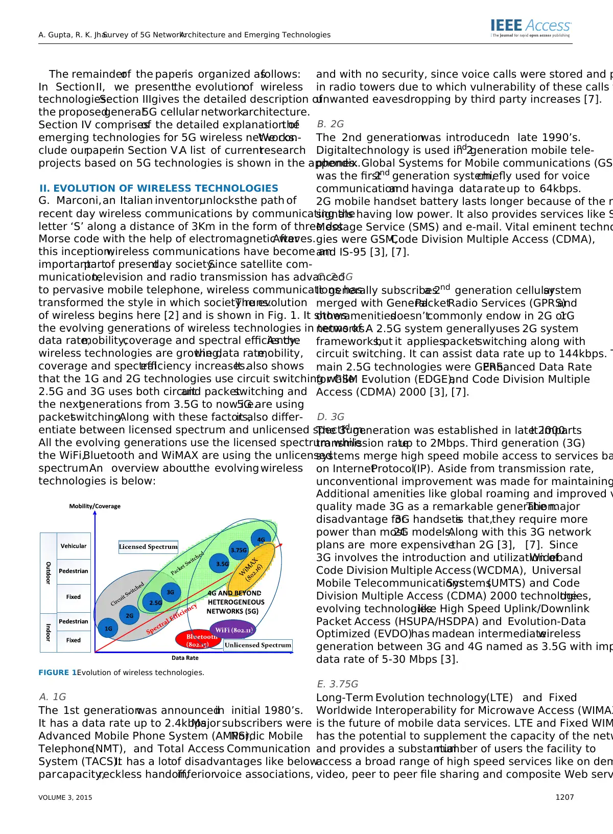
transformed the style in which society runs.The evolution
of wireless begins here [2] and is shown in Fig. 1. It shows
the evolving generations of wireless technologies in terms of
data rate,mobility,coverage and spectral efficiency.As the
wireless technologies are growing,the data rate,mobility,
coverage and spectralefficiency increases.It also shows
that the 1G and 2G technologies use circuit switching while
2.5G and 3G uses both circuitand packetswitching and
the nextgenerations from 3.5G to now i.e.5G are using
packetswitching.Along with these factors,it also differ-
entiate between licensed spectrum and unlicensed spectrum.
All the evolving generations use the licensed spectrum while
the WiFi,Bluetooth and WiMAX are using the unlicensed
spectrum.An overview aboutthe evolving wireless
technologies is below:
FIGURE 1.Evolution of wireless technologies.
A. 1G
The 1st generationwas announcedin initial 1980’s.
It has a data rate up to 2.4kbps.Major subscribers were
Advanced Mobile Phone System (AMPS),Nordic Mobile
Telephone(NMT), and Total Access Communication
System (TACS).It has a lotof disadvantages like below
parcapacity,reckless handoff,inferiorvoice associations,
and with no security, since voice calls were stored and p
in radio towers due to which vulnerability of these calls f
unwanted eavesdropping by third party increases [7].
B. 2G
The 2nd generationwas introducedin late 1990’s.
Digitaltechnology is used in 2nd generation mobile tele-
phones. Global Systems for Mobile communications (GSM
was the first2nd generation system,chiefly used for voice
communicationand havinga datarate up to 64kbps.
2G mobile handset battery lasts longer because of the r
signals having low power. It also provides services like S
Message Service (SMS) and e-mail. Vital eminent techno
gies were GSM,Code Division Multiple Access (CDMA),
and IS-95 [3], [7].
C. 2.5G
It generally subscribesa 2nd generation cellularsystem
merged with GeneralPacketRadio Services (GPRS)and
otheramenitiesdoesn’tcommonly endow in 2G or1G
networks.A 2.5G system generallyuses 2G system
frameworks,but it appliespacketswitching along with
circuit switching. It can assist data rate up to 144kbps. T
main 2.5G technologies were GPRS,Enhanced Data Rate
for GSM Evolution (EDGE),and Code Division Multiple
Access (CDMA) 2000 [3], [7].
D. 3G
The 3rd generation was established in late 2000.It imparts
transmission rateup to 2Mbps. Third generation (3G)
systems merge high speed mobile access to services ba
on InternetProtocol(IP). Aside from transmission rate,
unconventional improvement was made for maintaining
Additional amenities like global roaming and improved v
quality made 3G as a remarkable generation.The major
disadvantage for3G handsetsis that,they require more
power than most2G models.Along with this 3G network
plans are more expensivethan 2G [3], [7]. Since
3G involves the introduction and utilization ofWideband
Code Division Multiple Access (WCDMA), Universal
Mobile TelecommunicationsSystems(UMTS) and Code
Division Multiple Access (CDMA) 2000 technologies,the
evolving technologieslike High Speed Uplink/Downlink
Packet Access (HSUPA/HSDPA) and Evolution-Data
Optimized (EVDO)has madean intermediatewireless
generation between 3G and 4G named as 3.5G with imp
data rate of 5-30 Mbps [3].
E. 3.75G
Long-Term Evolution technology(LTE) and Fixed
Worldwide Interoperability for Microwave Access (WIMAX
is the future of mobile data services. LTE and Fixed WIM
has the potential to supplement the capacity of the netw
and provides a substantialnumber of users the facility to
access a broad range of high speed services like on dem
video, peer to peer file sharing and composite Web serv
VOLUME 3, 2015 1207
The remainderof the paperis organized asfollows:
In SectionII, we presentthe evolutionof wireless
technologies.Section IIIgives the detailed description of
the proposedgeneral5G cellular networkarchitecture.
Section IV comprisesof the detailed explanation ofthe
emerging technologies for 5G wireless networks.We con-
clude ourpaperin Section V.A list of currentresearch
projects based on 5G technologies is shown in the appendix.
II. EVOLUTION OF WIRELESS TECHNOLOGIES
G. Marconi,an Italian inventor,unlocksthe path of
recent day wireless communications by communicating the
letter ‘S’ along a distance of 3Km in the form of three dot
Morse code with the help of electromagnetic waves.After
this inception,wireless communications have become an
importantpartof presentday society.Since satellite com-
munication,television and radio transmission has advanced
to pervasive mobile telephone, wireless communications has
transformed the style in which society runs.The evolution
of wireless begins here [2] and is shown in Fig. 1. It shows
the evolving generations of wireless technologies in terms of
data rate,mobility,coverage and spectral efficiency.As the
wireless technologies are growing,the data rate,mobility,
coverage and spectralefficiency increases.It also shows
that the 1G and 2G technologies use circuit switching while
2.5G and 3G uses both circuitand packetswitching and
the nextgenerations from 3.5G to now i.e.5G are using
packetswitching.Along with these factors,it also differ-
entiate between licensed spectrum and unlicensed spectrum.
All the evolving generations use the licensed spectrum while
the WiFi,Bluetooth and WiMAX are using the unlicensed
spectrum.An overview aboutthe evolving wireless
technologies is below:
FIGURE 1.Evolution of wireless technologies.
A. 1G
The 1st generationwas announcedin initial 1980’s.
It has a data rate up to 2.4kbps.Major subscribers were
Advanced Mobile Phone System (AMPS),Nordic Mobile
Telephone(NMT), and Total Access Communication
System (TACS).It has a lotof disadvantages like below
parcapacity,reckless handoff,inferiorvoice associations,
and with no security, since voice calls were stored and p
in radio towers due to which vulnerability of these calls f
unwanted eavesdropping by third party increases [7].
B. 2G
The 2nd generationwas introducedin late 1990’s.
Digitaltechnology is used in 2nd generation mobile tele-
phones. Global Systems for Mobile communications (GSM
was the first2nd generation system,chiefly used for voice
communicationand havinga datarate up to 64kbps.
2G mobile handset battery lasts longer because of the r
signals having low power. It also provides services like S
Message Service (SMS) and e-mail. Vital eminent techno
gies were GSM,Code Division Multiple Access (CDMA),
and IS-95 [3], [7].
C. 2.5G
It generally subscribesa 2nd generation cellularsystem
merged with GeneralPacketRadio Services (GPRS)and
otheramenitiesdoesn’tcommonly endow in 2G or1G
networks.A 2.5G system generallyuses 2G system
frameworks,but it appliespacketswitching along with
circuit switching. It can assist data rate up to 144kbps. T
main 2.5G technologies were GPRS,Enhanced Data Rate
for GSM Evolution (EDGE),and Code Division Multiple
Access (CDMA) 2000 [3], [7].
D. 3G
The 3rd generation was established in late 2000.It imparts
transmission rateup to 2Mbps. Third generation (3G)
systems merge high speed mobile access to services ba
on InternetProtocol(IP). Aside from transmission rate,
unconventional improvement was made for maintaining
Additional amenities like global roaming and improved v
quality made 3G as a remarkable generation.The major
disadvantage for3G handsetsis that,they require more
power than most2G models.Along with this 3G network
plans are more expensivethan 2G [3], [7]. Since
3G involves the introduction and utilization ofWideband
Code Division Multiple Access (WCDMA), Universal
Mobile TelecommunicationsSystems(UMTS) and Code
Division Multiple Access (CDMA) 2000 technologies,the
evolving technologieslike High Speed Uplink/Downlink
Packet Access (HSUPA/HSDPA) and Evolution-Data
Optimized (EVDO)has madean intermediatewireless
generation between 3G and 4G named as 3.5G with imp
data rate of 5-30 Mbps [3].
E. 3.75G
Long-Term Evolution technology(LTE) and Fixed
Worldwide Interoperability for Microwave Access (WIMAX
is the future of mobile data services. LTE and Fixed WIM
has the potential to supplement the capacity of the netw
and provides a substantialnumber of users the facility to
access a broad range of high speed services like on dem
video, peer to peer file sharing and composite Web serv
VOLUME 3, 2015 1207
A. Gupta, R. K. Jha:Survey of 5G Network:Architecture and Emerging Technologies
Along with this,a supplementary spectrum is accessible
which accredit operators manage their network very compli-
antly and offers better coverage with improved performance
for less cost [4]–[7].
F. 4G
4G is generally referred as the descendant of the 3G and 2G
standards.3rd GenerationPartnershipProject (3GPP)
is presentlystandardizingLong Term Evolution(LTE)
Advanced as forthcoming 4G standard along with Mobile
Worldwide Interoperability for Microwave Access (WIMAX).
A 4G system improvesthe prevailingcommunication
networks by imparting a complete and reliable solution based
on IP. Amenities like voice,data and multimedia willbe
imparted to subscribers on every time and everywhere basis
and at quite higher data rates as related to earlier generations.
Applications thatare being made to use a 4G network are
MultimediaMessagingService(MMS), Digital Video
Broadcasting (DVB),and video chat,High Definition TV
content and mobile TV [2], [4]–[6].
G. 5G
With an exponentialincrease in the demand of the users,
4G will now be easily replacedwith 5G with an
advanced access technology named Beam Division Multiple
Access (BDMA) and Non- and quasi-orthogonalor Filter
Bank multicarrier(FBMC) multiple access.The concept
behind BDMA technique is explained by considering the case
of the base station communicating with the mobile stations.
In this communication,an orthogonalbeam is allocated to
each mobile station and BDMA technique willdivide that
antenna beam according to locations of the mobile stations
for giving multiple accesses to the mobile stations,which
correspondingly increase the capacity ofthe system [8].
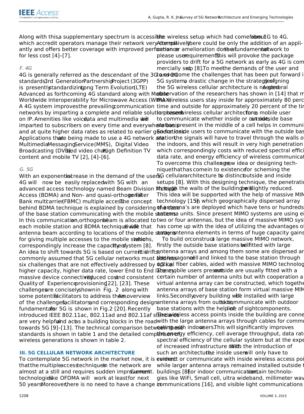
An idea to shift towards 5G is based on current drifts,it is
commonly assumed that 5G cellular networks must address
six challenges that are not effectively addressed by 4G i.e.
higher capacity, higher data rate, lower End to End latency,
massive device connectivity,reduced costand consistent
Quality of Experienceprovisioning[22], [23]. These
challengesare conciselyshownin Fig. 2 along with
some potentialfacilitators to address them.An overview
of the challenges,facilitators,and corresponding design
fundamentalsfor 5G is shown in Fig.2 [20]. Recently
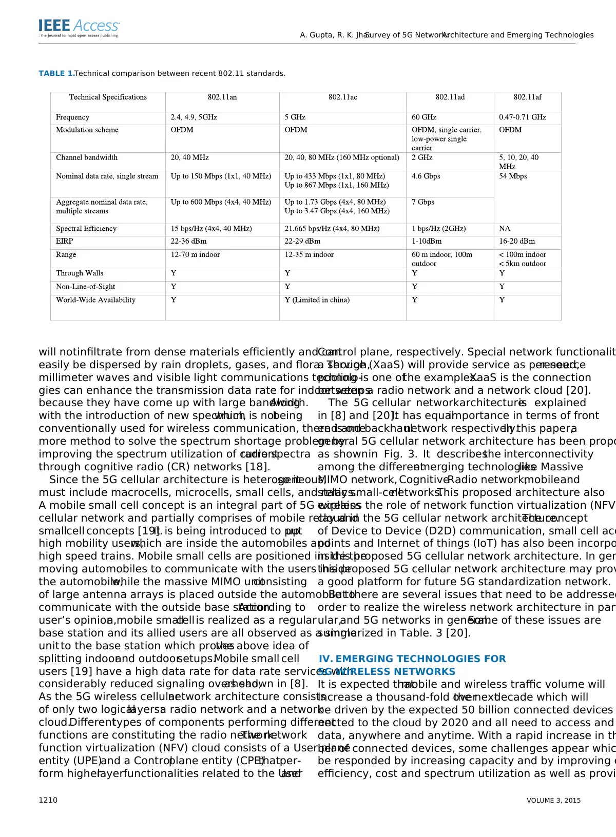
introduced IEEE 802.11ac, 802.11ad and 802.11af standards
are very helpfuland actas a building blocks in the road
towards 5G [9]–[13]. The technical comparison between these
standards is shown in table 1 and the detailed comparison of
wireless generations is shown in table 2.
III. 5G CELLULAR NETWORK ARCHITECTURE
To contemplate 5G network in the market now, it is evident
thatthe multipleaccesstechniquesin the network are
almost at a still and requires sudden improvement.Current
technologieslike OFDMA will work at leastfor next
50 years.Moreover,there is no need to have a change in
the wireless setup which had come aboutfrom 1G to 4G.
Alternatively,there could be only the addition of an appli-
cation or amelioration done atthe fundamentalnetwork to
please userrequirements.This will provoke the package
providers to drift for a 5G network as early as 4G is com
mercially setup [8].To meetthe demands of the user and
to overcome the challenges that has been put forward in
5G system,a drastic change in the strategy ofdesigning
the 5G wireless cellular architecture is needed.A general
observation of the researchers has shown in [14] that m
the wireless users stay inside for approximately 80 perc
time and outside for approximately 20 percent of the tim
In presentwireless cellular architecture,for a mobile user
to communicate whether inside or outside,an outside base
station present in the middle of a cell helps in communic
So for inside users to communicate with the outside bas
station,the signals will have to travel through the walls of
the indoors, and this will result in very high penetration
which correspondingly costs with reduced spectral effici
data rate, and energy efficiency of wireless communicat
To overcome this challenge,a new idea or designing tech-
niquethathas comein to existencefor scheming the
5G cellulararchitecture isto distinctoutside and inside
setups [8]. With this designing technique, the penetratio
through the walls of the building willbe slightly reduced.
This idea will be supported with the help of massive MIM
technology [15],in which geographically dispersed array
of antenna’s are deployed which have tens or hundreds
antenna units. Since present MIMO systems are using ei
two or four antennas, but the idea of massive MIMO syst
has come up with the idea of utilizing the advantages of
array antenna elements in terms of huge capacity gains
To build orconstructa large massive MIMO network,
firstly the outside base stations willbe fitted with large
antenna arrays and among them some are dispersed aro
the hexagonalcell and linked to the base station through
optical fiber cables, aided with massive MIMO technolog
The mobile users presentoutside are usually fitted with a
certain number of antenna units but with cooperation a
virtual antenna array can be constructed, which togethe
antenna arrays of base station form virtual massive MIM
links.Secondly,every building willbe installed with large
antenna arrays from outside,to communicate with outdoor
base stations with the help ofline of sightcomponents.
The wireless access points inside the building are conne
with the large antenna arrays through cables for commu
cating with indoorusers.This will significantly improves
the energy efficiency, cell average throughput, data rate
spectral efficiency of the cellular system but at the expe
of increased infrastructure cost.With the introduction of
such an architecture,the inside userswill only have to
connect or communicate with inside wireless access poi
while larger antenna arrays remained installed outside t
buildings [8].For indoor communication,certain technolo-
gies like WiFi, Small cell, ultra wideband, millimeter wav
communications [16], and visible light communications
1208 VOLUME 3, 2015
Along with this,a supplementary spectrum is accessible
which accredit operators manage their network very compli-
antly and offers better coverage with improved performance
for less cost [4]–[7].
F. 4G
4G is generally referred as the descendant of the 3G and 2G
standards.3rd GenerationPartnershipProject (3GPP)
is presentlystandardizingLong Term Evolution(LTE)
Advanced as forthcoming 4G standard along with Mobile
Worldwide Interoperability for Microwave Access (WIMAX).
A 4G system improvesthe prevailingcommunication
networks by imparting a complete and reliable solution based
on IP. Amenities like voice,data and multimedia willbe
imparted to subscribers on every time and everywhere basis
and at quite higher data rates as related to earlier generations.
Applications thatare being made to use a 4G network are
MultimediaMessagingService(MMS), Digital Video
Broadcasting (DVB),and video chat,High Definition TV
content and mobile TV [2], [4]–[6].
G. 5G
With an exponentialincrease in the demand of the users,
4G will now be easily replacedwith 5G with an
advanced access technology named Beam Division Multiple
Access (BDMA) and Non- and quasi-orthogonalor Filter
Bank multicarrier(FBMC) multiple access.The concept
behind BDMA technique is explained by considering the case
of the base station communicating with the mobile stations.
In this communication,an orthogonalbeam is allocated to
each mobile station and BDMA technique willdivide that
antenna beam according to locations of the mobile stations
for giving multiple accesses to the mobile stations,which
correspondingly increase the capacity ofthe system [8].
An idea to shift towards 5G is based on current drifts,it is
commonly assumed that 5G cellular networks must address
six challenges that are not effectively addressed by 4G i.e.
higher capacity, higher data rate, lower End to End latency,
massive device connectivity,reduced costand consistent
Quality of Experienceprovisioning[22], [23]. These
challengesare conciselyshownin Fig. 2 along with
some potentialfacilitators to address them.An overview
of the challenges,facilitators,and corresponding design
fundamentalsfor 5G is shown in Fig.2 [20]. Recently
introduced IEEE 802.11ac, 802.11ad and 802.11af standards
are very helpfuland actas a building blocks in the road
towards 5G [9]–[13]. The technical comparison between these
standards is shown in table 1 and the detailed comparison of
wireless generations is shown in table 2.
III. 5G CELLULAR NETWORK ARCHITECTURE
To contemplate 5G network in the market now, it is evident
thatthe multipleaccesstechniquesin the network are
almost at a still and requires sudden improvement.Current
technologieslike OFDMA will work at leastfor next
50 years.Moreover,there is no need to have a change in
the wireless setup which had come aboutfrom 1G to 4G.
Alternatively,there could be only the addition of an appli-
cation or amelioration done atthe fundamentalnetwork to
please userrequirements.This will provoke the package
providers to drift for a 5G network as early as 4G is com
mercially setup [8].To meetthe demands of the user and
to overcome the challenges that has been put forward in
5G system,a drastic change in the strategy ofdesigning
the 5G wireless cellular architecture is needed.A general
observation of the researchers has shown in [14] that m
the wireless users stay inside for approximately 80 perc
time and outside for approximately 20 percent of the tim
In presentwireless cellular architecture,for a mobile user
to communicate whether inside or outside,an outside base
station present in the middle of a cell helps in communic
So for inside users to communicate with the outside bas
station,the signals will have to travel through the walls of
the indoors, and this will result in very high penetration
which correspondingly costs with reduced spectral effici
data rate, and energy efficiency of wireless communicat
To overcome this challenge,a new idea or designing tech-
niquethathas comein to existencefor scheming the
5G cellulararchitecture isto distinctoutside and inside
setups [8]. With this designing technique, the penetratio
through the walls of the building willbe slightly reduced.
This idea will be supported with the help of massive MIM
technology [15],in which geographically dispersed array
of antenna’s are deployed which have tens or hundreds
antenna units. Since present MIMO systems are using ei
two or four antennas, but the idea of massive MIMO syst
has come up with the idea of utilizing the advantages of
array antenna elements in terms of huge capacity gains
To build orconstructa large massive MIMO network,
firstly the outside base stations willbe fitted with large
antenna arrays and among them some are dispersed aro
the hexagonalcell and linked to the base station through
optical fiber cables, aided with massive MIMO technolog
The mobile users presentoutside are usually fitted with a
certain number of antenna units but with cooperation a
virtual antenna array can be constructed, which togethe
antenna arrays of base station form virtual massive MIM
links.Secondly,every building willbe installed with large
antenna arrays from outside,to communicate with outdoor
base stations with the help ofline of sightcomponents.
The wireless access points inside the building are conne
with the large antenna arrays through cables for commu
cating with indoorusers.This will significantly improves
the energy efficiency, cell average throughput, data rate
spectral efficiency of the cellular system but at the expe
of increased infrastructure cost.With the introduction of
such an architecture,the inside userswill only have to
connect or communicate with inside wireless access poi
while larger antenna arrays remained installed outside t
buildings [8].For indoor communication,certain technolo-
gies like WiFi, Small cell, ultra wideband, millimeter wav
communications [16], and visible light communications
1208 VOLUME 3, 2015
⊘ This is a preview!⊘
Do you want full access?
Subscribe today to unlock all pages.
Trusted by 1+ million students worldwide
A. Gupta, R. K. Jha:Survey of 5G Network:Architecture and Emerging Technologies
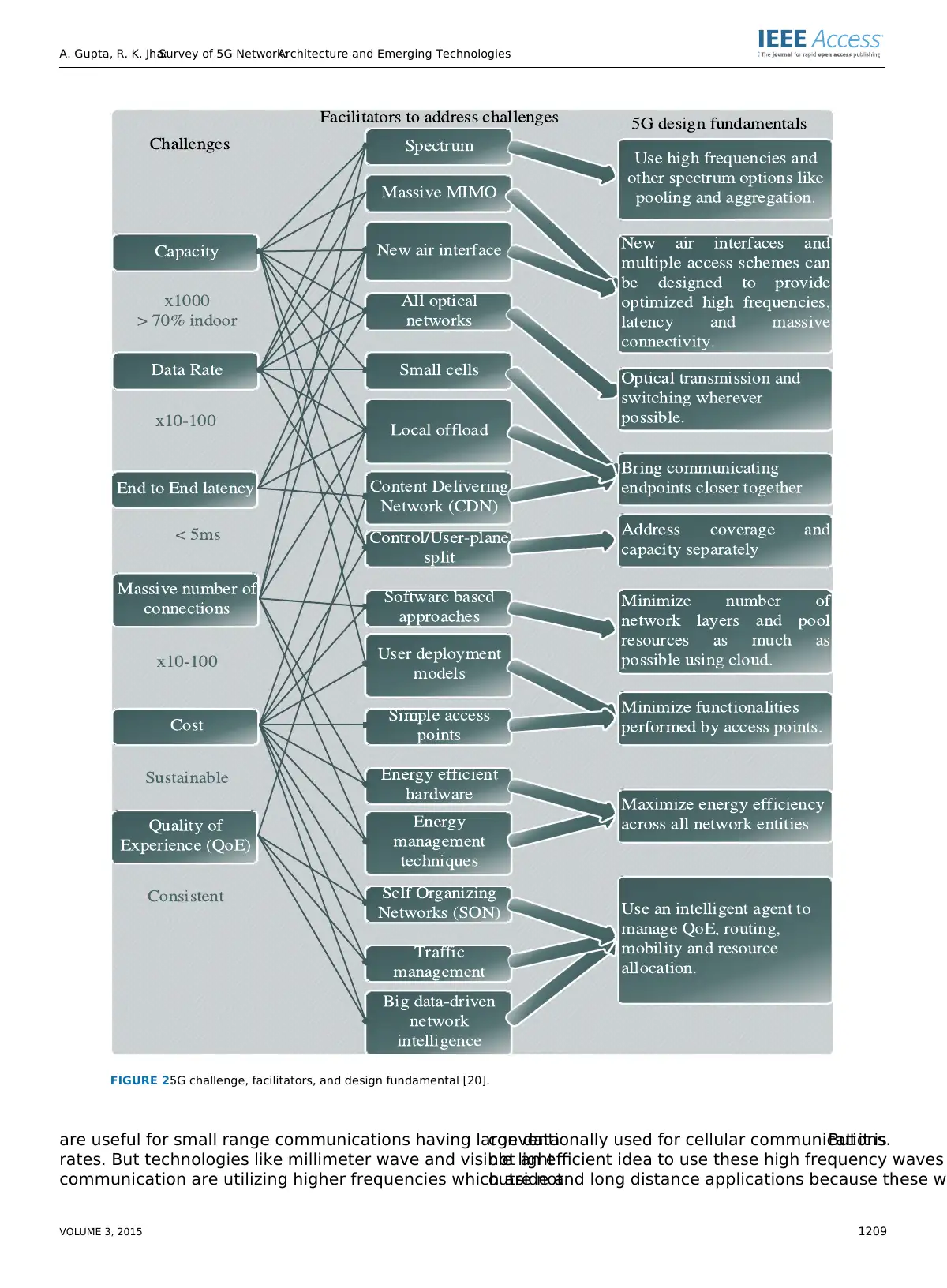
FIGURE 2.5G challenge, facilitators, and design fundamental [20].
are useful for small range communications having large data
rates. But technologies like millimeter wave and visible light
communication are utilizing higher frequencies which are not
conventionally used for cellular communications.But it is
not an efficient idea to use these high frequency waves
outside and long distance applications because these wa
VOLUME 3, 2015 1209
Paraphrase This Document
Need a fresh take? Get an instant paraphrase of this document with our AI Paraphraser
A. Gupta, R. K. Jha:Survey of 5G Network:Architecture and Emerging Technologies
TABLE 1.Technical comparison between recent 802.11 standards.
will notinfiltrate from dense materials efficiently and can
easily be dispersed by rain droplets, gases, and flora. Though,
millimeter waves and visible light communications technolo-
gies can enhance the transmission data rate for indoor setups
because they have come up with large bandwidth.Along
with the introduction of new spectrum,which is notbeing
conventionally used for wireless communication, there is one
more method to solve the spectrum shortage problem by
improving the spectrum utilization of currentradio spectra
through cognitive radio (CR) networks [18].
Since the 5G cellular architecture is heterogeneous,so it
must include macrocells, microcells, small cells, and relays.
A mobile small cell concept is an integral part of 5G wireless
cellular network and partially comprises of mobile relay and
smallcell concepts [19].It is being introduced to putup
high mobility users,which are inside the automobiles and
high speed trains. Mobile small cells are positioned inside the
moving automobiles to communicate with the users inside
the automobile,while the massive MIMO unitconsisting
of large antenna arrays is placed outside the automobile to
communicate with the outside base station.According to
user’s opinion,a mobile smallcell is realized as a regular
base station and its allied users are all observed as a single
unit to the base station which provesthe above idea of
splitting indoorand outdoorsetups.Mobile small cell
users [19] have a high data rate for data rate services with
considerably reduced signaling overhead,as shown in [8].
As the 5G wireless cellularnetwork architecture consists
of only two logicallayers:a radio network and a network
cloud.Differenttypes of components performing different
functions are constituting the radio network.The network
function virtualization (NFV) cloud consists of a User plane
entity (UPE)and a Controlplane entity (CPE)thatper-
form higherlayerfunctionalities related to the Userand
Control plane, respectively. Special network functionalit
a service (XaaS) will provide service as per need,resource
pooling is one ofthe examples.XaaS is the connection
between a radio network and a network cloud [20].
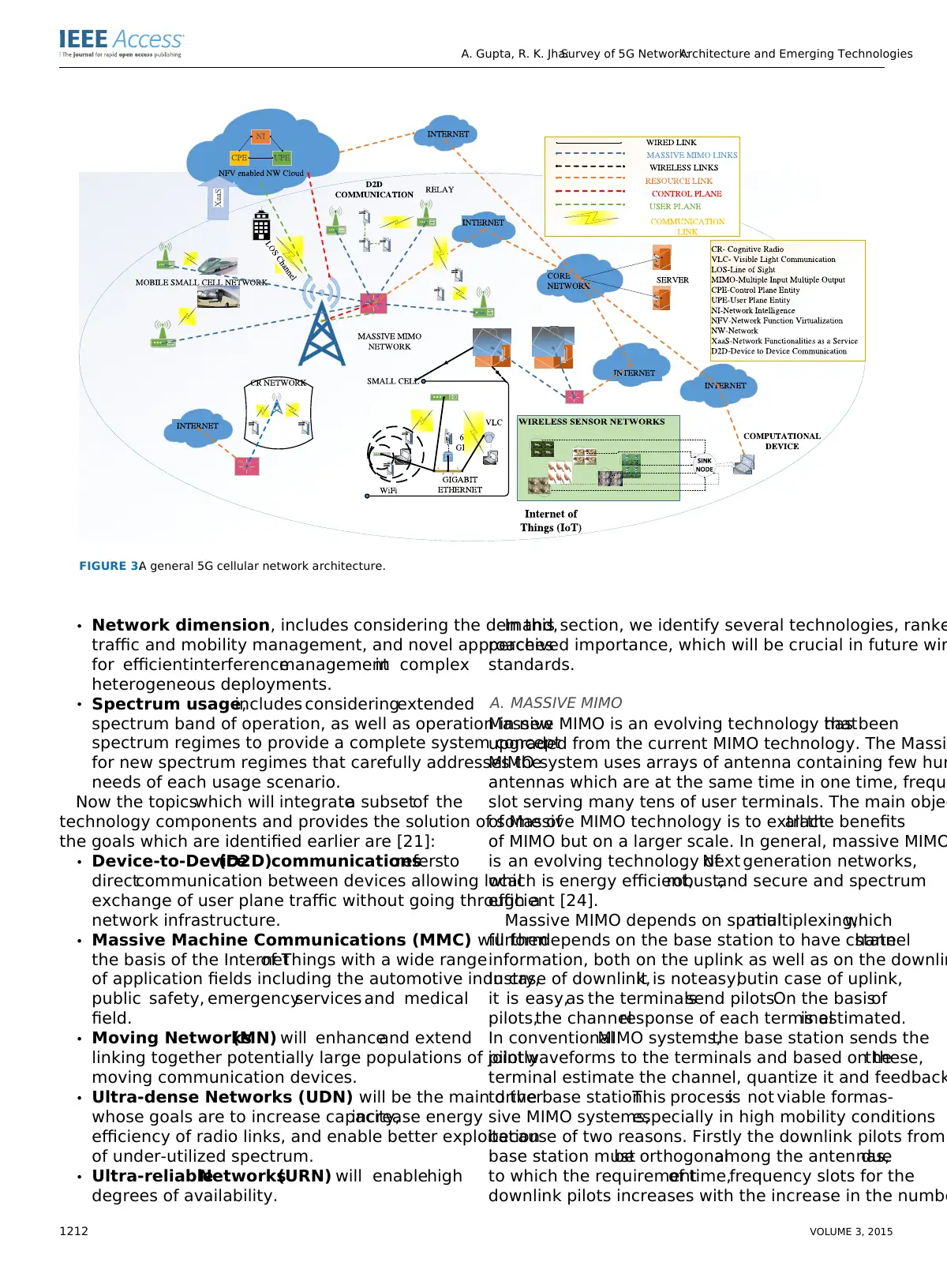
The 5G cellular networkarchitectureis explained
in [8] and [20].It has equalimportance in terms of front
end and backhaulnetwork respectively.In this paper,a
general 5G cellular network architecture has been propo
as shownin Fig. 3. It describesthe interconnectivity
among the differentemerging technologieslike Massive
MIMO network, CognitiveRadio network,mobileand
static small-cellnetworks.This proposed architecture also
explains the role of network function virtualization (NFV)
cloud in the 5G cellular network architecture.The concept
of Device to Device (D2D) communication, small cell acc
points and Internet of things (IoT) has also been incorpo
in this proposed 5G cellular network architecture. In gen
this proposed 5G cellular network architecture may prov
a good platform for future 5G standardization network.
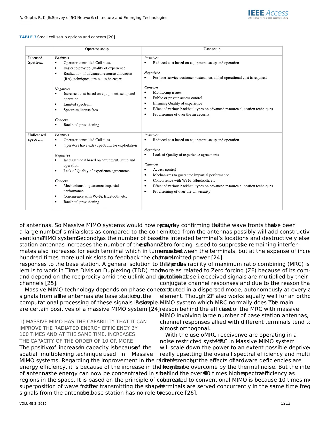
But there are several issues that need to be addressed
order to realize the wireless network architecture in part
ular,and 5G networks in general.Some of these issues are
summarized in Table. 3 [20].
IV. EMERGING TECHNOLOGIES FOR
5G WIRELESS NETWORKS
It is expected thatmobile and wireless traffic volume will
increase a thousand-fold overthe nextdecade which will
be driven by the expected 50 billion connected devices
nected to the cloud by 2020 and all need to access and
data, anywhere and anytime. With a rapid increase in th
ber of connected devices, some challenges appear whic
be responded by increasing capacity and by improving e
efficiency, cost and spectrum utilization as well as provi
1210 VOLUME 3, 2015
TABLE 1.Technical comparison between recent 802.11 standards.
will notinfiltrate from dense materials efficiently and can
easily be dispersed by rain droplets, gases, and flora. Though,
millimeter waves and visible light communications technolo-
gies can enhance the transmission data rate for indoor setups
because they have come up with large bandwidth.Along
with the introduction of new spectrum,which is notbeing
conventionally used for wireless communication, there is one
more method to solve the spectrum shortage problem by
improving the spectrum utilization of currentradio spectra
through cognitive radio (CR) networks [18].
Since the 5G cellular architecture is heterogeneous,so it
must include macrocells, microcells, small cells, and relays.
A mobile small cell concept is an integral part of 5G wireless
cellular network and partially comprises of mobile relay and
smallcell concepts [19].It is being introduced to putup
high mobility users,which are inside the automobiles and
high speed trains. Mobile small cells are positioned inside the
moving automobiles to communicate with the users inside
the automobile,while the massive MIMO unitconsisting
of large antenna arrays is placed outside the automobile to
communicate with the outside base station.According to
user’s opinion,a mobile smallcell is realized as a regular
base station and its allied users are all observed as a single
unit to the base station which provesthe above idea of
splitting indoorand outdoorsetups.Mobile small cell
users [19] have a high data rate for data rate services with
considerably reduced signaling overhead,as shown in [8].
As the 5G wireless cellularnetwork architecture consists
of only two logicallayers:a radio network and a network
cloud.Differenttypes of components performing different
functions are constituting the radio network.The network
function virtualization (NFV) cloud consists of a User plane
entity (UPE)and a Controlplane entity (CPE)thatper-
form higherlayerfunctionalities related to the Userand
Control plane, respectively. Special network functionalit
a service (XaaS) will provide service as per need,resource
pooling is one ofthe examples.XaaS is the connection
between a radio network and a network cloud [20].
The 5G cellular networkarchitectureis explained
in [8] and [20].It has equalimportance in terms of front
end and backhaulnetwork respectively.In this paper,a
general 5G cellular network architecture has been propo
as shownin Fig. 3. It describesthe interconnectivity
among the differentemerging technologieslike Massive
MIMO network, CognitiveRadio network,mobileand
static small-cellnetworks.This proposed architecture also
explains the role of network function virtualization (NFV)
cloud in the 5G cellular network architecture.The concept
of Device to Device (D2D) communication, small cell acc
points and Internet of things (IoT) has also been incorpo
in this proposed 5G cellular network architecture. In gen
this proposed 5G cellular network architecture may prov
a good platform for future 5G standardization network.
But there are several issues that need to be addressed
order to realize the wireless network architecture in part
ular,and 5G networks in general.Some of these issues are
summarized in Table. 3 [20].
IV. EMERGING TECHNOLOGIES FOR
5G WIRELESS NETWORKS
It is expected thatmobile and wireless traffic volume will
increase a thousand-fold overthe nextdecade which will
be driven by the expected 50 billion connected devices
nected to the cloud by 2020 and all need to access and
data, anywhere and anytime. With a rapid increase in th
ber of connected devices, some challenges appear whic
be responded by increasing capacity and by improving e
efficiency, cost and spectrum utilization as well as provi
1210 VOLUME 3, 2015
A. Gupta, R. K. Jha:Survey of 5G Network:Architecture and Emerging Technologies
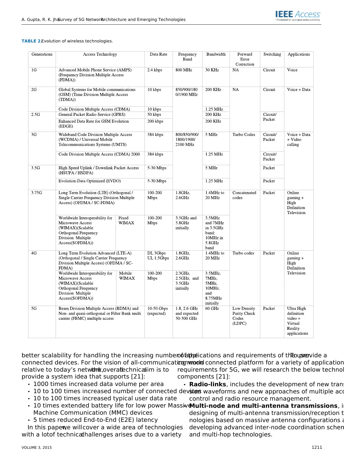
TABLE 2.Evolution of wireless technologies.
better scalability for handling the increasing number of the
connected devices. For the vision of all-communicating world
relative to today’s network,the overalltechnicalaim is to
provide a system idea that supports [21]:
• 1000 times increased data volume per area
• 10 to 100 times increased number of connected devices
• 10 to 100 times increased typical user data rate
• 10 times extended battery life for low power Massive
Machine Communication (MMC) devices
• 5 times reduced End-to-End (E2E) latency
In this paper,we willcover a wide area of technologies
with a lotof technicalchallenges arises due to a variety
of applications and requirements of the user.To provide a
common connected platform for a variety of application
requirements for 5G, we will research the below technol
components [21]:
• Radio-links, includes the development of new trans
sion waveforms and new approaches of multiple acc
control and radio resource management.
• Multi-node and multi-antenna transmissions, in
designing of multi-antenna transmission/reception te
nologies based on massive antenna configurations a
developing advanced inter-node coordination schem
and multi-hop technologies.
VOLUME 3, 2015 1211
⊘ This is a preview!⊘
Do you want full access?
Subscribe today to unlock all pages.
Trusted by 1+ million students worldwide
A. Gupta, R. K. Jha:Survey of 5G Network:Architecture and Emerging Technologies
FIGURE 3.A general 5G cellular network architecture.
• Network dimension, includes considering the demand,
traffic and mobility management, and novel approaches
for efficientinterferencemanagementin complex
heterogeneous deployments.
• Spectrum usage,includes consideringextended
spectrum band of operation, as well as operation in new
spectrum regimes to provide a complete system concept
for new spectrum regimes that carefully addresses the
needs of each usage scenario.
Now the topicswhich will integratea subsetof the
technology components and provides the solution of some of
the goals which are identified earlier are [21]:
• Device-to-Device(D2D)communicationsrefersto
directcommunication between devices allowing local
exchange of user plane traffic without going through a
network infrastructure.
• Massive Machine Communications (MMC) will form
the basis of the Internetof Things with a wide range
of application fields including the automotive industry,
public safety, emergencyservices and medical
field.
• Moving Networks(MN) will enhanceand extend
linking together potentially large populations of jointly
moving communication devices.
• Ultra-dense Networks (UDN) will be the main driver
whose goals are to increase capacity,increase energy
efficiency of radio links, and enable better exploitation
of under-utilized spectrum.
• Ultra-reliableNetworks(URN) will enablehigh
degrees of availability.
In this section, we identify several technologies, ranke
perceived importance, which will be crucial in future wir
standards.
A. MASSIVE MIMO
Massive MIMO is an evolving technology thathas been
upgraded from the current MIMO technology. The Massiv
MIMO system uses arrays of antenna containing few hun
antennas which are at the same time in one time, freque
slot serving many tens of user terminals. The main objec
of Massive MIMO technology is to extractall the benefits
of MIMO but on a larger scale. In general, massive MIMO
is an evolving technology ofNext generation networks,
which is energy efficient,robust,and secure and spectrum
efficient [24].
Massive MIMO depends on spatialmultiplexing,which
furtherdepends on the base station to have channelstate
information, both on the uplink as well as on the downlin
In case of downlink,it is noteasy,butin case of uplink,
it is easy,as the terminalssend pilots.On the basisof
pilots,the channelresponse of each terminalis estimated.
In conventionalMIMO systems,the base station sends the
pilotwaveforms to the terminals and based on these,the
terminal estimate the channel, quantize it and feedback
to the base station.This processis not viable formas-
sive MIMO systems,especially in high mobility conditions
because of two reasons. Firstly the downlink pilots from
base station mustbe orthogonalamong the antennas,due
to which the requirementof time,frequency slots for the
downlink pilots increases with the increase in the numbe
1212 VOLUME 3, 2015
Paraphrase This Document
Need a fresh take? Get an instant paraphrase of this document with our AI Paraphraser
A. Gupta, R. K. Jha:Survey of 5G Network:Architecture and Emerging Technologies
TABLE 3.Small cell setup options and concern [20].
of antennas. So Massive MIMO systems would now require
a large numberof similarslots as compared to the con-
ventionalMIMO system.Secondly,as the number of base
station antennas increases the number of the channelesti-
mates also increases for each terminal which in turn needed
hundred times more uplink slots to feedback the channel
responses to the base station. A general solution to this prob-
lem is to work in Time Division Duplexing (TDD) mode
and depend on the reciprocity amid the uplink and downlink
channels [25].
Massive MIMO technology depends on phase coherent
signals from allthe antennas atthe base station,butthe
computational processing of these signals is simple.Below
are certain positives of a massive MIMO system [24]:
1) MASSIVE MIMO HAS THE CAPABILITY THAT IT CAN
IMPROVE THE RADIATED ENERGY EFFICIENCY BY
100 TIMES AND AT THE SAME TIME, INCREASES
THE CAPACITY OF THE ORDER OF 10 OR MORE
The positiveof increasein capacity isbecauseof the
spatial multiplexing technique used in Massive
MIMO systems. Regarding the improvement in the radiated
energy efficiency, it is because of the increase in the number
of antennas,the energy can now be concentrated in small
regions in the space. It is based on the principle of coherent
superposition of wave fronts.After transmitting the shaped
signals from the antennas,the base station has no role to
play by confirming thatall the wave fronts thathave been
emitted from the antennas possibly will add constructive
the intended terminal’s locations and destructively elsew
Zero forcing isused to suppressthe remaining interfer-
ence between the terminals, but at the expense of incre
transmitted power [24].
The desirability of maximum ratio combining (MRC) is
more as related to Zero forcing (ZF) because of its com-
putationalease i.e.received signals are multiplied by their
conjugate channel responses and due to the reason that
executed in a dispersed mode, autonomously at every a
element. Though ZF also works equally well for an ortho
MIMO system which MRC normally does not.The main
reason behind the efficientuse of the MRC with massive
MIMO involving large number of base station antennas,
channel responses allied with different terminals tend to
almost orthogonal.
With the use ofMRC receiver,we are operating in a
noise restricted system.MRC in Massive MIMO system
will scale down the power to an extent possible deprived
really upsetting the overall spectral efficiency and multi
interference,butthe effects ofhardware deficiencies are
likely to be overcome by the thermal noise. But the inte
behind the overall10 times higherspectralefficiency as
compared to conventional MIMO is because 10 times mo
terminals are served concurrently in the same time freq
resource [26].
VOLUME 3, 2015 1213
A. Gupta, R. K. Jha:Survey of 5G Network:Architecture and Emerging Technologies
2) MASSIVE MIMO SYSTEMS CAN BE PUT TOGETHER
WITH THE HELP OF LOW POWER AND
LESS COSTLY COMPONENTS
Massive MIMO has come up with a changewith
respectto concept,schemesand execution.Massive
MIMO systems use hundreds of less expensive amplifiers in
respect to expensive ultra-linear 50 Watt amplifiers because
earlier are having an outputpower in the milliwattrange,
which is much betterthan the latterwhich are generally
being used in conventional systems.It is dissimilar to con-
ventional array schemes, as it will use only a little antenna’s
that are being fed from high power amplifiers but having a
notable impact.The most significant improvement is about
the removal of a large number of expensive and massive items
like large coaxial cables [24].
With the use of a large number of antennas in massive
MIMO technology the noise,fading and hardware deficits
will be averaged because signals from a large numberof
antennas are combined together in the free space. It condenses
the limits on precision and linearity of every single amplifier
and radio frequency chain and altogetherwhatmatters is
their collective action.This willincrease the robustness of
massive MIMO againstfading and failure ofone of the
antenna elements.
A massive MIMO system has degrees of freedom in excess.
For example,with 100 antennas,10 terminals are showing
presence while the remaining 90 degrees offreedom are
still available.These available degrees of freedom can be
exploited by using them for signalshaping which willbe
hardware friendly. Specifically, each antenna with the use of
very cheap and power proficient radio frequency amplifiers
can transmit signals having small peak to average ratio [27]
and constant envelope [28] at a modest price of increased total
radiated power. With the help of constant envelope multiuser
precoding,the signals transmitted from each antenna are
neither being formed in terms of beam nor by weighing of
a symbol. Rather, a wave field is created and sampled with
respectto the location ofthe terminals and they can see
precisely the signals whatwe intended to make them see.
Massive MIMO has a vital property which makes it possible.
The massive MIMO channel has large null spaces in which
nearly everything can be engaged withoutdisturbing the
terminals.Precisely modules can be placed into this null
spacethatmakesthe transmitted waveformsfulfill the
preferred envelope restraints.Nevertheless,the operative
channels amid the base station and every terminal,can be
proceeded without the involvement of PSK type modulation
and can take any signal constellation as input [24].
The considerable improvementin the energy efficiency
facilitates massive MIMO systems to work two steps of lower
magnitude than with existing technology on the total output
RF power. This is important because the cellular base stations
are consuming a lot of power and it is an area of concern.
In addition, if base stations that consume less power could be
driven by renewable resources like solar or wind and therefore
it is helpfulto deploy base stations to the places where
electricity is notavailable.Along with this,the increased
concerns of electromagnetic exposure willbe considerably
less.
3) MASSIVE MIMO PERMITS A SUBSTANTIAL DECREASE
IN LATENCY ON THE AIR INTERFACE
Latency is the prime area of concern in the next generat
networks.In wireless communication,the main cause of
latency is fading.This phenomenon occurs amid the base
station and terminal, i.e. when the signal is transmitted
the base station,it travels through differentmultiple paths
because of the phenomenon’s like scattering, reflection
diffraction before itreaches the terminal.When the signal
through these multiple paths reaches the terminal it will
fere either constructively or destructively, and the case
following waves from these multiple paths interfere dest
tively, the received signal strength reduces to a conside
low point. If the terminal is caught in a fading dip, then i
to wait for the transmission channel to change until any
can be received.Massive MIMO,due to a large number of
antennas and with the idea of beam forming can avoid f
dips and now latency cannot be further decreased [24].
4) MASSIVE MIMO MAKES THE MULTIPLE
ACCESS LAYER SIMPLE
With the arrivalof Massive MIMO,the channelstrength-
ens and now frequency domain scheduling is notenough.
OFDM provides, each subcarrier in a massive MIMO syst
with considerably the same channel gain due to which e
and every terminal can be provided with complete band
which reduces most of the physical layer control signalin
terminated [24].
5) MASSIVE MIMO INCREASES THE STRENGTH EQUALLY
AGAINST UNINTENDED MAN MADE INTERFERENCE
AND INTENDED JAMMING
Jammingof the wirelesssystemsof the civilian is a
prime area of concern and poses a serious threatto cyber
security.Owing to limited bandwidth,the distribution of
information overfrequency justis not possible.Massive
MIMO offers the methodsof improving robustnessof
wireless communications with the help of multiple anten
It provides with an excess of degrees of freedom thatcan
be useful for canceling the signals from intended jamme
If massive MIMO systems use joint channel estimation a
decoding instead ofuplink pilots forchannelestimation,
then the problem from the intended jammers is conside
reduced [24].
The advantagesof massiveMIMO systems can be
reviewed from an information theoreticpoint of view.
Massive MIMO systems can obtain the promising multi-
plexing gain ofmassive pointto pointMIMO systems,
while eliminating problems due to unfavorable propagat
environments [29].
1214 VOLUME 3, 2015
⊘ This is a preview!⊘
Do you want full access?
Subscribe today to unlock all pages.
Trusted by 1+ million students worldwide
A. Gupta, R. K. Jha:Survey of 5G Network:Architecture and Emerging Technologies
Let us study a massive MIMO system having L cells, where
every cell has K attended single antenna users and one base
station with N antennas. hi,k ,l,nrepresent the channel coeffi-
cient from the k-th user in the l-th cell to the n-th antenna of
the i-th base station, which is equivalent to a complex small
scale fading factor time an amplitude factor that interprets for
geometric attenuation and large-scale fading:
hi,k ,l,n= gi,k ,l,n
p di,k ,l (1)
Where gi,k ,l,nand di,k ,lrepresent complex small scale fad-
ing and large scale fading coefficients, respectively. The small
scale fading coefficients are implicit to be diverse for diverse
users or for diverse antennas atevery base station though
the large scale fading coefficients are the same for diverse
antennas atthe same base station,butare user dependent.
Then, the channel matrix from all K users in the l-th cell to
the i-th base station can be expressed as
Hi,l =
hi,1,l,1 · · · hi,K ,l,1
... ... ...
hi,1,l,N · · · hi,K ,l,N
= Gi,l D1/2
i,l (2)
Where
Gi,l =
gi,1,l,1 · · · gi,K ,l,1
... ... ...
gi,1,l,N · · · gi.K ,l,N
(3)
Di,c =
di,1,l · · · . . .
... ... ...
. . . · · · di.K ,l
(4)
Let us study a single cell (L = 1) massive MIMO system
with K singled antennausersand a basestation with
N antennas. For ease, the cell and the base station indices are
plunged when single cell systems are deliberated [29].
a: UPLINK
The received signal vector at a single base station for uplink
signal transmission is denoted as yu ∈ CN ∗1, can be stated as:
yu = √ ρuHxu + nu (5)
where xu ∈ C K ∗1is the signalvectorfrom allusers,
H ∈ C N∗K is the uplink channel matrix defined in (2) by
reducing the cell and the base station indices, nu ∈ CN ∗1is
a zero mean noise vector with complex Gaussian distribution
and identity covariance matrix, and ρu is the uplink transmit
power. The transmitted symbol from the k-th user, xu
k, is the
k-th element of xu = [xu
1, . . . ., xu
K ]T with [|xu
k|2] = 1.
The column channel vectors from diverse users are asymp-
totically orthogonalas the number of antennas atthe base
station,N, grows to infinity by supposing thatthe small
scale fading coefficients for diverse users is independent [30].
Then, we have
HH H = D1/2GH GD1/2 ≈ ND1/2IK D1/2 = ND (6)
An exhaustive debate about this result can be seen in
Centered on the result in (6), the overall achievable rate
users come to be
C = log2 det(I + ρuHH H )
≈ log2 det(I + N ρuD)
=
KX
k=1
log2 (1 + Nρudk)
bits
s
Hz (7)
Capacity in (7)can be achieved atthe base station by
simple MF processing.When MF processing is used,the
base station processes the signalvector by multiplying the
conjugate transpose of the channel, as
HH yu = HH √ ρuHxu + nu
≈ N√ ρuDxu + HH nu (8)
where (6) is used. Note that the channel vectors are a
totically orthogonal when the number of antennas at the
station grows to infinity.So,HH does not shade the noise.
Since D is a diagonal matrix,the MF processing splits the
signals from diverse users into diverse streams and ther
asymptotically no inter user interference. So now the sig
transmission can be treated as a SISO channel transmis
for each user. From (8), the signal to noise ratio (SNR) fo
k-th user is N ρudk. Subsequently, the attainable rate by usi
MF is similar as the limit in (7), which indicates that simp
MF processing at the base station is best when the num
antennas at the base station, N, grows to infinity.
b: DOWNLINK
yd ∈ CK ∗1can be denoted as the received signal vector a
all K users. Massive MIMO works properly in time division
duplexing (TDD) mode as discussed in [29], where the d
link channelis the transpose of the uplink channelmatrix.
Then, the received signal vector can be expressed as
yd = √ ρdHT xd + nd (9)
where xd ∈ CN ∗1is the signal vector transmitted by the
base station,nd ∈ CK ∗1is an additive noise and ρd is the
transmit power of the downlink. Let us assume, E[|xd|2] = 1
for normalizing transmitting power.
As discussed in [29], the base station usually has chan
state information equivalent to all users based on uplink
transmission. So, it is likely for the base station to do po
allocation for maximizing the sum transmission rate. The
capacity of the system with power allocation is [32]
C = max
p log2 det(IN + ρdHPHH )
≈ max
p log2 det(IK + ρdNPD)
bits
s
Hz (10)
where (6) is used and P is a positive diagonal matrix w
the power allocations (p1, . . . .., pk) as its diagonal elements
andP K
k=1pk = 1
If the MF precoder is used, the transmitted signal vect
xd = H ∗ D−1/2P1/2sd (11)
VOLUME 3, 2015 1215
Paraphrase This Document
Need a fresh take? Get an instant paraphrase of this document with our AI Paraphraser
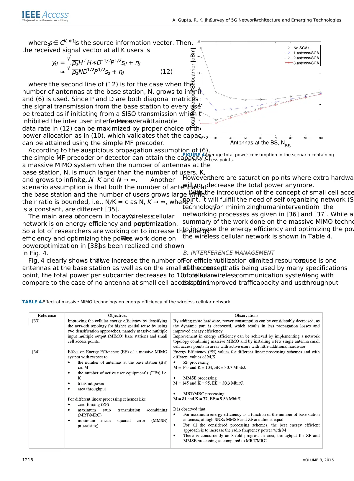
A. Gupta, R. K. Jha:Survey of 5G Network:Architecture and Emerging Technologies
where sd ∈ CK ∗1is the source information vector. Then,
the received signal vector at all K users is
yd = √ ρdHT H∗D−1/2P1/2sd + nd
≈ √ ρdND1/2P1/2sd + nd (12)
where the second line of (12) is for the case when the
number of antennas at the base station, N, grows to infinity,
and (6) is used. Since P and D are both diagonal matrices so
the signal transmission from the base station to every user can
be treated as if initiating from a SISO transmission which thus
inhibited the inter user interference.The overallattainable
data rate in (12) can be maximized by proper choice of the
power allocation as in (10), which validates that the capacity
can be attained using the simple MF precoder.
According to the auspicious propagation assumption of (6),
the simple MF precoder or detector can attain the capacity of
a massive MIMO system when the number of antennas at the
base station, N, is much larger than the number of users, K,
and grows to infinity,i.e.,N K and N → ∞. Another
scenario assumption is that both the number of antennas at
the base station and the number of users grows large while
their ratio is bounded, i.e., N/K = c as N, K → ∞, where c
is a constant, are different [35].
The main area ofconcern in today’swirelesscellular
network is on energy efficiency and poweroptimization.
So a lot of researchers are working on to increase the energy
efficiency and optimizing the power.The work done on
poweroptimization in [33]has been realized and shown
in Fig. 4.
Fig. 4 clearly shows thatif we increase the number of
antennas at the base station as well as on the small cell access
point, the total power per subcarrier decreases to 10 fold as
compare to the case of no antenna at small cell access point.
FIGURE 4.Average total power consumption in the scenario containing
small cell access points.
However,there are saturation points where extra hardwar
will not decrease the total power anymore.
With the introduction of the concept of small cell acce
point, it will fulfill the need of self organizing network (SO
technologyfor minimizinghumaninterventionin the
networking processes as given in [36] and [37]. While a
summary of the work done on the massive MIMO techno
to increase the energy efficiency and optimizing the pow
the wireless cellular network is shown in Table 4.
B. INTERFERENCE MANAGEMENT
For efficientutilization oflimited resources,reuse is one
of the conceptthatis being used by many specifications
of cellularwirelesscommunication systems.Along with
this, for improved trafficcapacity and userthroughput
TABLE 4.Effect of massive MIMO technology on energy efficiency of the wireless cellular network.
1216 VOLUME 3, 2015
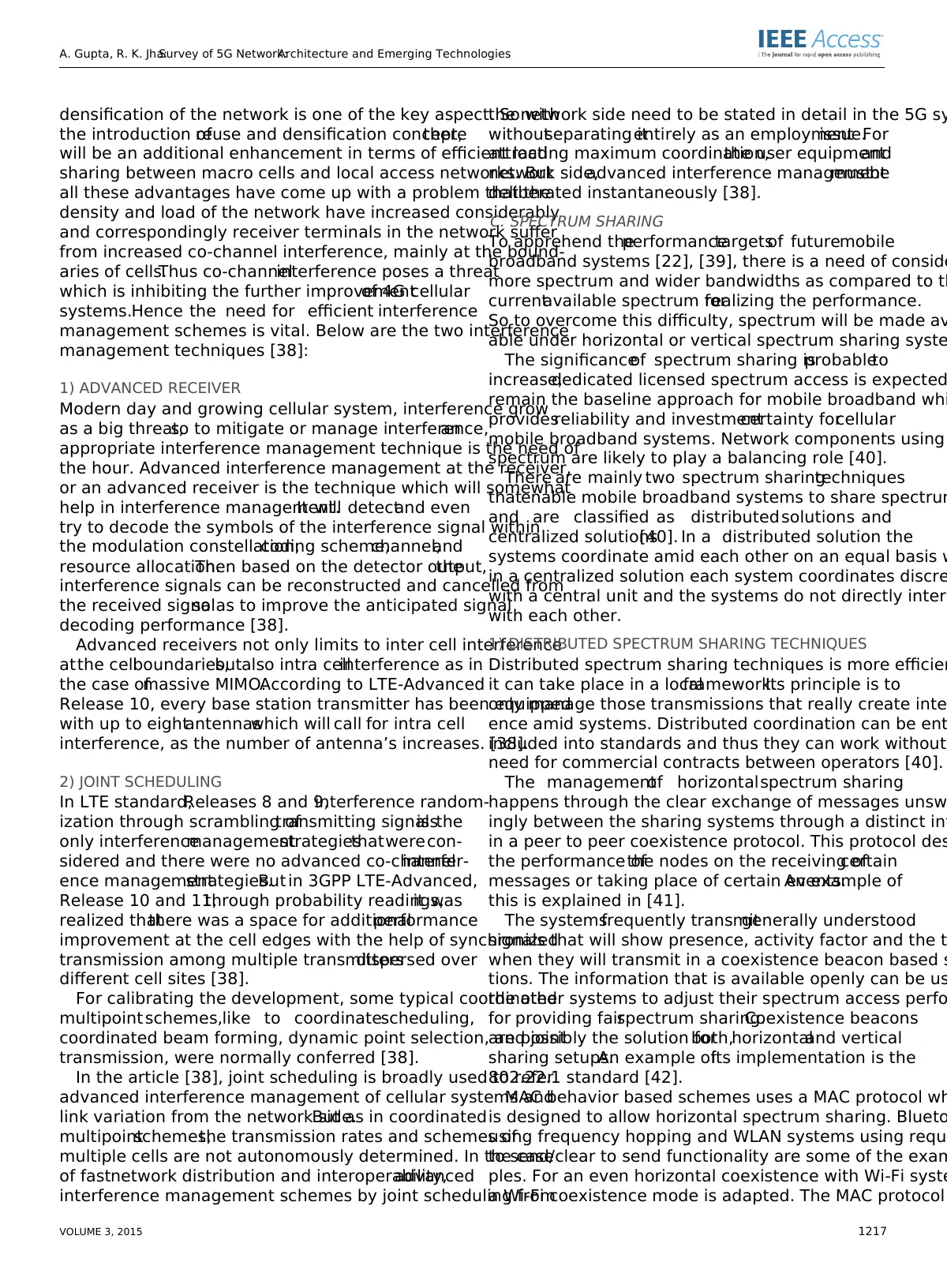
A. Gupta, R. K. Jha:Survey of 5G Network:Architecture and Emerging Technologies
densification of the network is one of the key aspect. So with
the introduction ofreuse and densification concept,there
will be an additional enhancement in terms of efficient load
sharing between macro cells and local access networks. But
all these advantages have come up with a problem that the
density and load of the network have increased considerably
and correspondingly receiver terminals in the network suffer
from increased co-channel interference, mainly at the bound-
aries of cells.Thus co-channelinterference poses a threat
which is inhibiting the further improvementof 4G cellular
systems.Hence the need for efficient interference
management schemes is vital. Below are the two interference
management techniques [38]:
1) ADVANCED RECEIVER
Modern day and growing cellular system, interference grow
as a big threat,so to mitigate or manage interference,an
appropriate interference management technique is the need of
the hour. Advanced interference management at the receiver,
or an advanced receiver is the technique which will somewhat
help in interference management.It will detectand even
try to decode the symbols of the interference signal within
the modulation constellation,coding scheme,channel,and
resource allocation.Then based on the detector output,the
interference signals can be reconstructed and cancelled from
the received signalso as to improve the anticipated signal
decoding performance [38].
Advanced receivers not only limits to inter cell interference
atthe cellboundaries,butalso intra cellinterference as in
the case ofmassive MIMO.According to LTE-Advanced
Release 10, every base station transmitter has been equipped
with up to eightantennaswhich will call for intra cell
interference, as the number of antenna’s increases. [38].
2) JOINT SCHEDULING
In LTE standard,Releases 8 and 9,interference random-
ization through scrambling oftransmitting signalsis the
only interferencemanagementstrategiesthatwerecon-
sidered and there were no advanced co-channelinterfer-
ence managementstrategies.But in 3GPP LTE-Advanced,
Release 10 and 11,through probability readings,it was
realized thatthere was a space for additionalperformance
improvement at the cell edges with the help of synchronized
transmission among multiple transmittersdispersed over
different cell sites [38].
For calibrating the development, some typical coordinated
multipoint schemes,like to coordinatescheduling,
coordinated beam forming, dynamic point selection, and joint
transmission, were normally conferred [38].
In the article [38], joint scheduling is broadly used to refer
advanced interference management of cellular systems and
link variation from the network side.But as in coordinated
multipointschemes,the transmission rates and schemes of
multiple cells are not autonomously determined. In the case
of fastnetwork distribution and interoperability,advanced
interference management schemes by joint scheduling from
the network side need to be stated in detail in the 5G sy
withoutseparating itentirely as an employmentissue.For
attracting maximum coordination,the user equipmentand
network side,advanced interference managementmustbe
deliberated instantaneously [38].
C. SPECTRUM SHARING
To apprehend theperformancetargetsof futuremobile
broadband systems [22], [39], there is a need of conside
more spectrum and wider bandwidths as compared to th
currentavailable spectrum forrealizing the performance.
So to overcome this difficulty, spectrum will be made av
able under horizontal or vertical spectrum sharing syste
The significanceof spectrum sharing isprobableto
increase,dedicated licensed spectrum access is expected
remain the baseline approach for mobile broadband whi
providesreliability and investmentcertainty forcellular
mobile broadband systems. Network components using
spectrum are likely to play a balancing role [40].
There are mainly two spectrum sharingtechniques
thatenable mobile broadband systems to share spectrum
and are classified as distributed solutions and
centralized solutions[40]. In a distributed solution the
systems coordinate amid each other on an equal basis w
in a centralized solution each system coordinates discre
with a central unit and the systems do not directly intera
with each other.
1) DISTRIBUTED SPECTRUM SHARING TECHNIQUES
Distributed spectrum sharing techniques is more efficien
it can take place in a localframework.Its principle is to
only manage those transmissions that really create inter
ence amid systems. Distributed coordination can be ent
included into standards and thus they can work without
need for commercial contracts between operators [40].
The managementof horizontalspectrum sharing
happens through the clear exchange of messages unsw
ingly between the sharing systems through a distinct int
in a peer to peer coexistence protocol. This protocol des
the performance ofthe nodes on the receiving ofcertain
messages or taking place of certain events.An example of
this is explained in [41].
The systemsfrequently transmitgenerally understood
signals that will show presence, activity factor and the t
when they will transmit in a coexistence beacon based s
tions. The information that is available openly can be us
the other systems to adjust their spectrum access perfo
for providing fairspectrum sharing.Coexistence beacons
are possibly the solution forboth,horizontaland vertical
sharing setups.An example ofits implementation is the
802.22.1 standard [42].
MAC behavior based schemes uses a MAC protocol wh
is designed to allow horizontal spectrum sharing. Blueto
using frequency hopping and WLAN systems using reque
to send/clear to send functionality are some of the exam
ples. For an even horizontal coexistence with Wi-Fi syste
a Wi-Fi coexistence mode is adapted. The MAC protocol
VOLUME 3, 2015 1217
⊘ This is a preview!⊘
Do you want full access?
Subscribe today to unlock all pages.
Trusted by 1+ million students worldwide
1 out of 27
Related Documents


Your All-in-One AI-Powered Toolkit for Academic Success.
+13062052269
info@desklib.com
Available 24*7 on WhatsApp / Email
![[object Object]](/_next/static/media/star-bottom.7253800d.svg)
Unlock your academic potential
Copyright © 2020–2026 A2Z Services. All Rights Reserved. Developed and managed by ZUCOL.