Design of a 5 GHz Wi-Fi Receiver Low Noise Amplifier Report
VerifiedAdded on 2022/08/28
|11
|1681
|25
Report
AI Summary
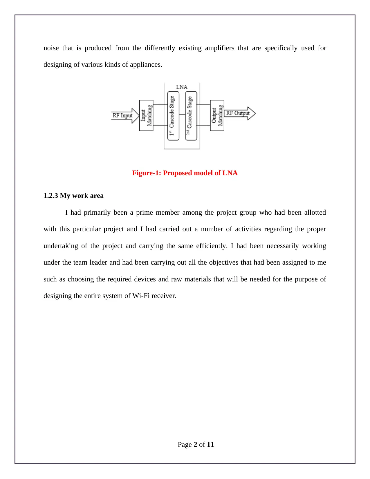
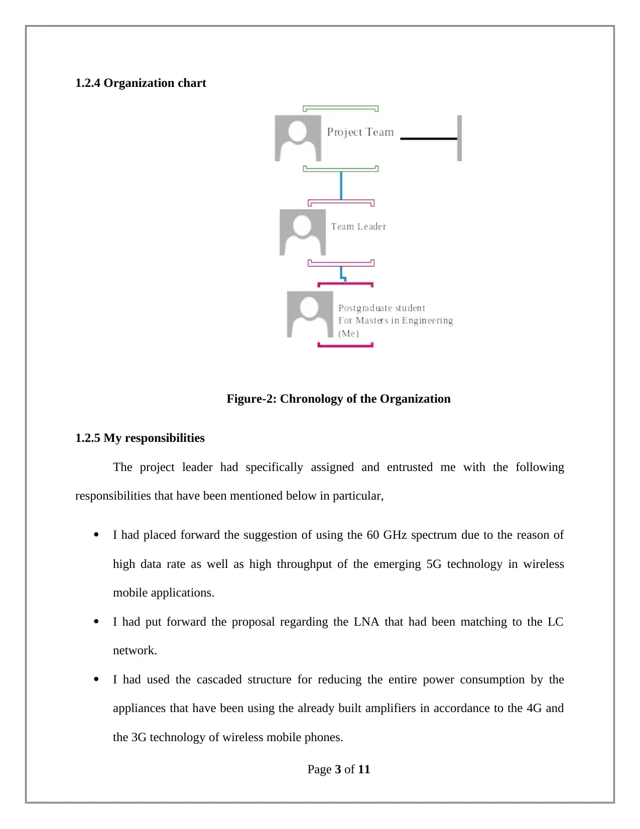
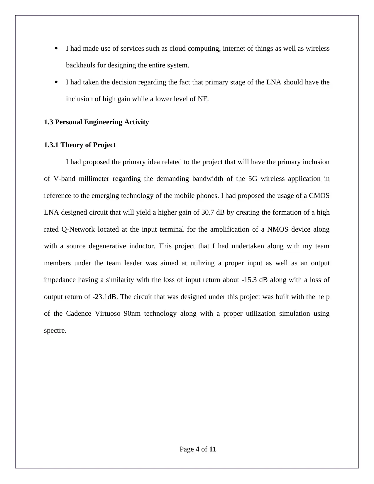
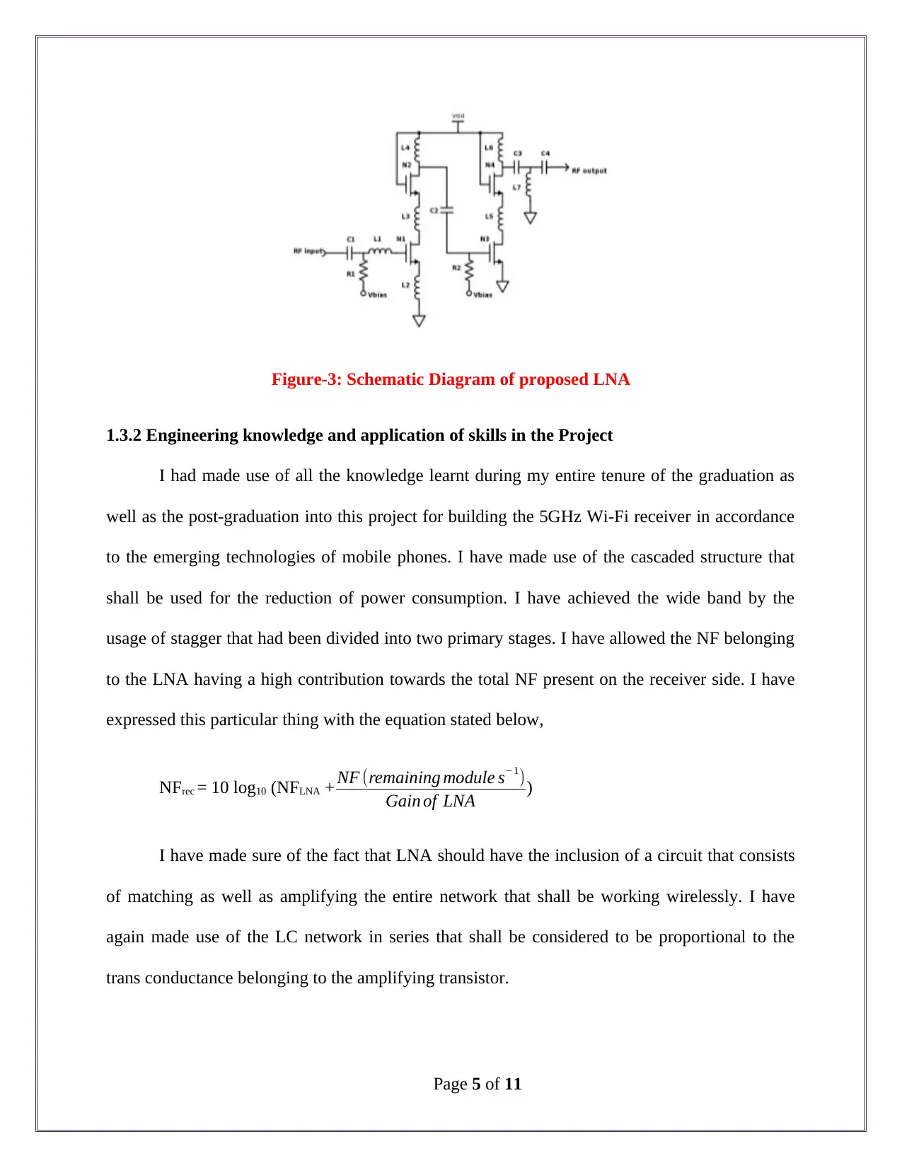
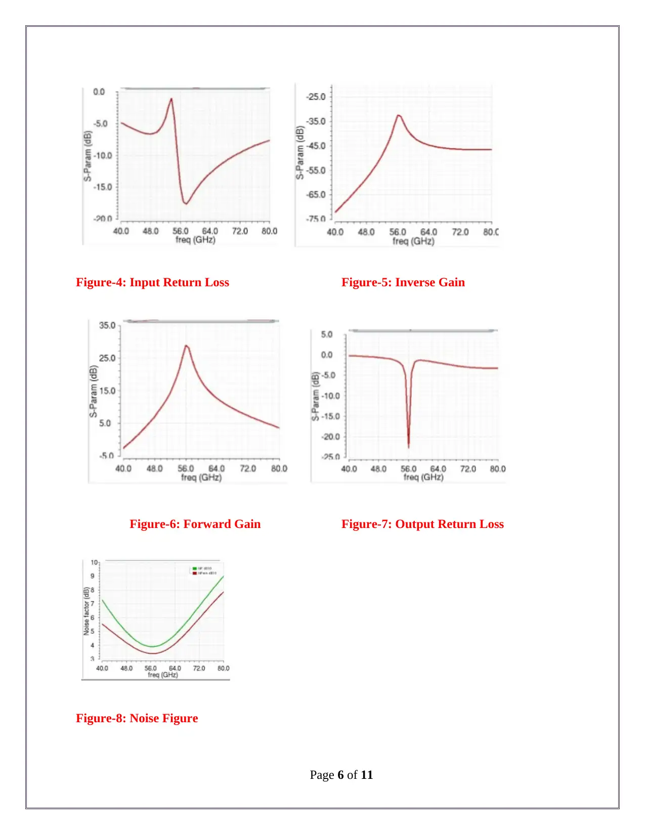
This report details the design of a 5 GHz Wi-Fi receiver Low Noise Amplifier (LNA) undertaken at Macquarie University. The project aimed to design an LNA to amplify received RF input signals while minimizing noise, crucial for wireless network access. The report covers the design process, including the...

Competency Demonstration Report (CDR)
Career Episode 2
Career Episode 2
Paraphrase This Document
Need a fresh take? Get an instant paraphrase of this document with our AI Paraphraser

1.0 Career Episode- 2
1.1 Introduction
Project Name: - Design of a 5-GHz Wi-Fi Receiver Low Noise Amplifier.
Location of the Project: - Macquarie University, Sydney, Australia.
Duration of the project: - [Please fill].
Organization: - Macquarie University.
Position within Project: - Masters of Engineering (Electronics Engineering Major)
postgraduate student.
1.2 Background
1.2.1 Characteristics of the Project
This project carries the primary objective of designing a 5 GHz Wi-Fi receiver that is a
low noise amplifier. This project has the primary requirements of building a Wi-Fi receiver that
will produce much lower levels of noise when placed inside an electronic appliance for a better
and an efficient functioning of the same. This project that I had undertaken shares a complete
relevance with the wireless applications in regards to the 5G technology.
1.2.2 Objective of the Project
The primary aim that was associated with this project was to design a 5 GHz Wi-Fi
receiver Low noise amplifier to attain a high gain as well as a linear wideband cascaded Low
Noise Amplifier (LNA) divided into two stages that will be operating at a range of 52 to that of
60 GHz primarily. This project also had the objective associated with the design to reduce the
Page 1 of 11

noise that is produced from the differently existing amplifiers that are specifically used for
designing of various kinds of appliances.
Figure-1: Proposed model of LNA
1.2.3 My work area
I had primarily been a prime member among the project group who had been allotted
with this particular project and I had carried out a number of activities regarding the proper
undertaking of the project and carrying the same efficiently. I had been necessarily working
under the team leader and had been carrying out all the objectives that had been assigned to me
such as choosing the required devices and raw materials that will be needed for the purpose of
designing the entire system of Wi-Fi receiver.
Page 2 of 11
You're viewing a preview
Unlock full access by subscribing today!

1.2.4 Organization chart
Figure-2: Chronology of the Organization
1.2.5 My responsibilities
The project leader had specifically assigned and entrusted me with the following
responsibilities that have been mentioned below in particular,
I had placed forward the suggestion of using the 60 GHz spectrum due to the reason of
high data rate as well as high throughput of the emerging 5G technology in wireless
mobile applications.
I had put forward the proposal regarding the LNA that had been matching to the LC
network.
I had used the cascaded structure for reducing the entire power consumption by the
appliances that have been using the already built amplifiers in accordance to the 4G and
the 3G technology of wireless mobile phones.
Page 3 of 11
Paraphrase This Document
Need a fresh take? Get an instant paraphrase of this document with our AI Paraphraser

I had made use of services such as cloud computing, internet of things as well as wireless
backhauls for designing the entire system.
I had taken the decision regarding the fact that primary stage of the LNA should have the
inclusion of high gain while a lower level of NF.
1.3 Personal Engineering Activity
1.3.1 Theory of Project
I had proposed the primary idea related to the project that will have the primary inclusion
of V-band millimeter regarding the demanding bandwidth of the 5G wireless application in
reference to the emerging technology of the mobile phones. I had proposed the usage of a CMOS
LNA designed circuit that will yield a higher gain of 30.7 dB by creating the formation of a high
rated Q-Network located at the input terminal for the amplification of a NMOS device along
with a source degenerative inductor. This project that I had undertaken along with my team
members under the team leader was aimed at utilizing a proper input as well as an output
impedance having a similarity with the loss of input return about -15.3 dB along with a loss of
output return of -23.1dB. The circuit that was designed under this project was built with the help
of the Cadence Virtuoso 90nm technology along with a proper utilization simulation using
spectre.
Page 4 of 11

Figure-3: Schematic Diagram of proposed LNA
1.3.2 Engineering knowledge and application of skills in the Project
I had made use of all the knowledge learnt during my entire tenure of the graduation as
well as the post-graduation into this project for building the 5GHz Wi-Fi receiver in accordance
to the emerging technologies of mobile phones. I have made use of the cascaded structure that
shall be used for the reduction of power consumption. I have achieved the wide band by the
usage of stagger that had been divided into two primary stages. I have allowed the NF belonging
to the LNA having a high contribution towards the total NF present on the receiver side. I have
expressed this particular thing with the equation stated below,
NFrec = 10 log10 (NFLNA + NF (remaining module s−1)
Gain of LNA )
I have made sure of the fact that LNA should have the inclusion of a circuit that consists
of matching as well as amplifying the entire network that shall be working wirelessly. I have
again made use of the LC network in series that shall be considered to be proportional to the
trans conductance belonging to the amplifying transistor.
Page 5 of 11
You're viewing a preview
Unlock full access by subscribing today!

Figure-4: Input Return Loss Figure-5: Inverse Gain
Figure-6: Forward Gain Figure-7: Output Return Loss
Figure-8: Noise Figure
Page 6 of 11
Figure-6: Forward Gain Figure-7: Output Return Loss
Figure-8: Noise Figure
Page 6 of 11
Paraphrase This Document
Need a fresh take? Get an instant paraphrase of this document with our AI Paraphraser

Figure-9: Comparison within proposed LNA with existing LNA’s
1.3.3 Tasks performed by me
The team leader had assigned me with the following tasks that I had carried out with
diligence during the entire procedure of the project. These are,
I had placed forward the proposal of using a CMOS LNA circuit that will necessarily
yield a higher rate of gain such as the like of 30.7dB by creating a formation of a high Q-
Network in reference to the input terminal for the amplification of the NMOS device.
I had placed forward the decision of using a Cadence Virtuoso 90nm technology for
designing the entire circuit.
I had proposed the usage of a LNA circuit that has the inclusion of matching as well as
amplifying the network.
I had written the quality factor of LC series network that is completely having an inverse
proportion to the transconductance belonging to the amplifying transistor.
Page 7 of 11

I had made a list of all the appliances as well as the devices that will be necessary for
designing the receiver in accordance to the applications of technology related to mobile
phones.
1.3.4 Issues identified and mitigated
Issues
I had identified the issue that the 3G and the 4G technology in accordance to the mobile
phone applications have a limitation below 6 GHz along with the occupancy of multiple
applications for mobile.
I had identified that the usage of two stage cascaded LNA that operates at 55 GHz
consists of NF having the value of 3.6dB that results in high rate of power consumption
along with lower amounts of gain.
Page 8 of 11
You're viewing a preview
Unlock full access by subscribing today!

Mitigation
In reference to the first issue that I had specifically identified, 5G millimeter wave is
considered to be a promising solution that I had placed forward in regards to the users of
the recent 5G technology.
To decrease the amount of power consumption, I had made proper utilization of the LNA
that has the primary inclusion of advantages in regards to the gain as well as the amount
of power consumption with the help of NF.
1.3.5 Collaborated work
I had been assigned for a number of activities and I had again entrusted myself with
multiple activities that I had carried out diligently with the help of my team member and under
the guidance of the team leader. I had specifically implemented my knowledge within the field of
my expertise in reference to the one that I gathered through the entire time of my graduation and
post-graduation within this project to design and build the 5G Wi-Fi receiver that will have a
lower rate of power consumption along with higher rate of inputs in reference to the usage of
various technologies with the help of mobile phones.
1.4 Summary
1.4.1 Overview of the Project
The entire project that I had undertaken along with my team members was to design a
5GHz Wi-Fi Receiver Low Noise Amplifier with the usage of various required applications and
devices that are necessarily needed. I have carried out the entire project with the usage of 5G
millimeter wave that will be the most effective solution for the users. The project has the primary
Page 9 of 11
Paraphrase This Document
Need a fresh take? Get an instant paraphrase of this document with our AI Paraphraser

objective to decrease the power consumption on a normal basis by the usage of LNA circuit
having the inclusion of NF.
1.4.2 Meeting of the goals
The primary goal that was a particular reason to undertake this project had been to
decrease the consumption of power by the amplifiers used within the 3G as well as 4G
technology. The objectives in accordance to the initial requirements of designing a 5G Wi-Fi
receiver has been successfully accomplished with the proper implementation of all the required
devices as well as the applications of engineering knowledge from all the members of the project
team.
1.4.3 Personal Contribution
I had diligently worked towards the responsibilities that have been entrusted upon me by
the team leader such as choosing the type of circuit that will be utilized for designing the entire
system of the project. I had calculated the power consumption of the previous amplifiers and
made suggestions of the amplifier that needs to be used in order to reduce the total consumption
of power in regards to the 5G technology of the mobile phones. I had lastly taken decisions
regarding the usage of other devices that had helped towards designing a more efficient circuit
for the undertaken project.
Page 10 of 11
1 out of 11
Related Documents

Your All-in-One AI-Powered Toolkit for Academic Success.
+13062052269
info@desklib.com
Available 24*7 on WhatsApp / Email
Unlock your academic potential
© 2024 | Zucol Services PVT LTD | All rights reserved.