Computer Organisation and Design: 8-Bit Arithmetic Logic Unit Project

Verified

Added on  2021/05/30

|14
|1400
|306
Project
AI Summary
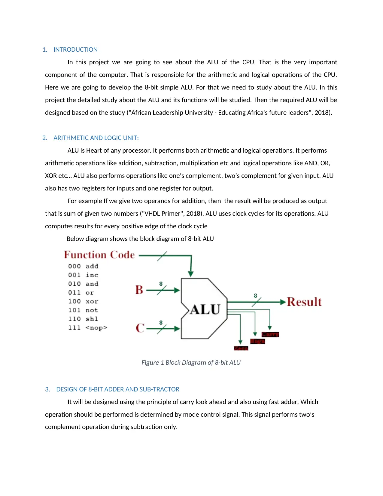
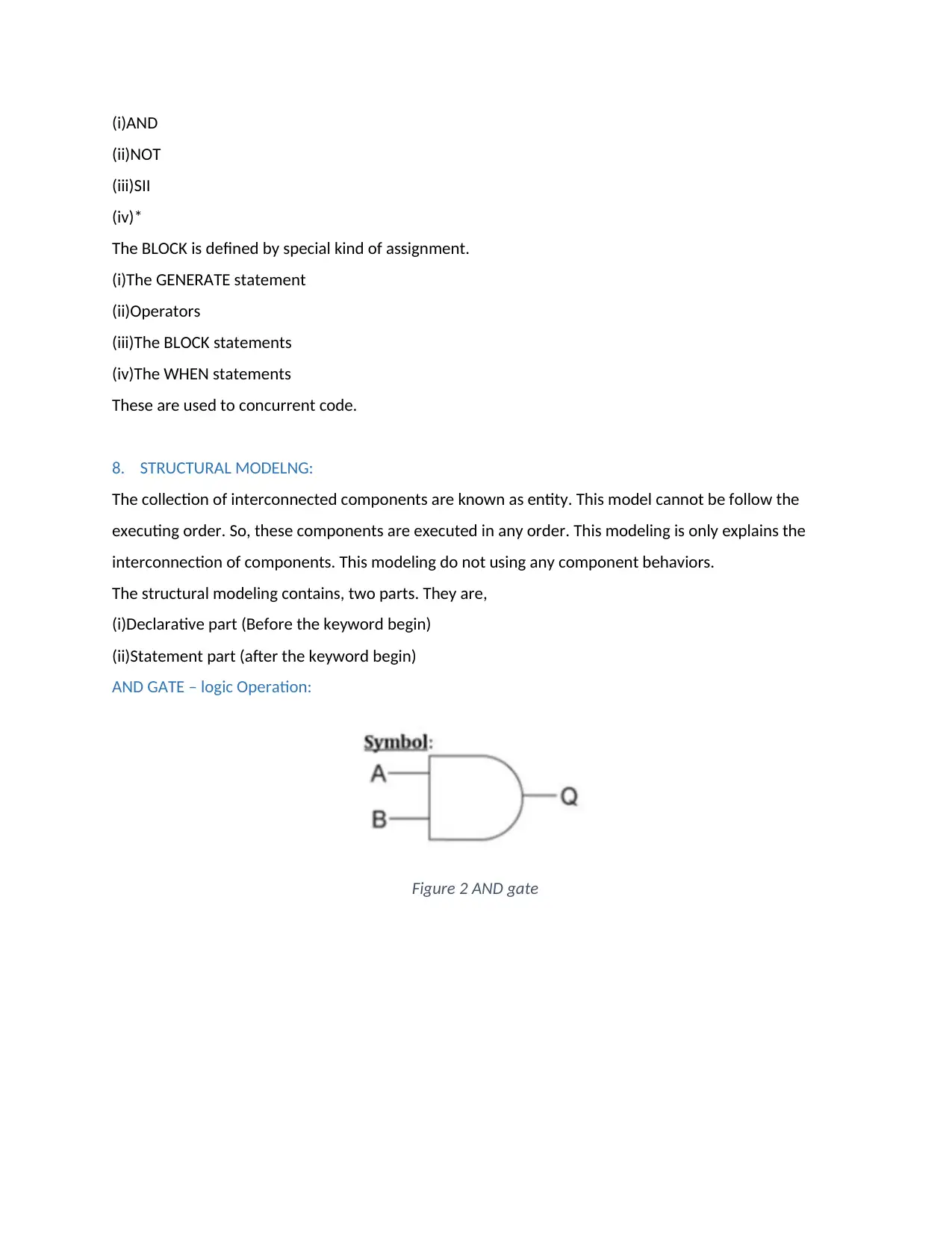
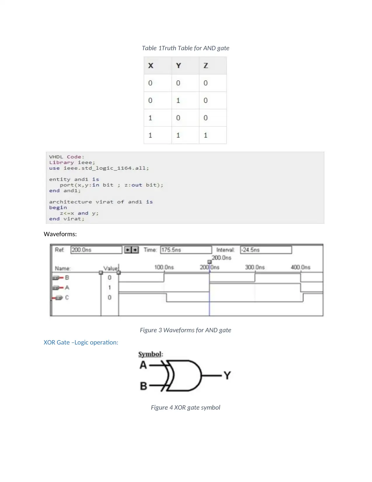
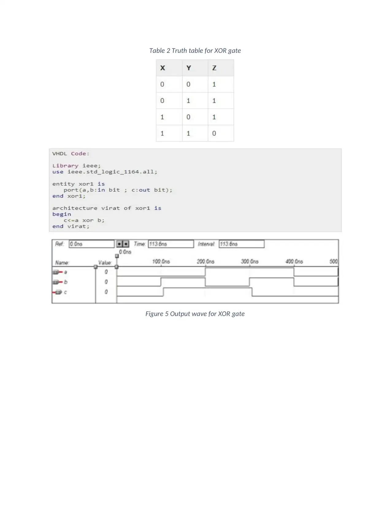
This project report details the design and implementation of an 8-bit Arithmetic Logic Unit (ALU). The project begins with an abstract and acknowledgment, followed by an introduction to the ALU and its significance in computer systems. The report then delves into the key components of the ALU, including the design of an 8-bit adder and subtractor, and an 8-bit logical block. The design process utilizes VHDL, with discussions on behavioral, dataflow, and structural modeling techniques. The report also includes the design and implementation of AND and XOR gates, with truth tables and waveform diagrams to illustrate their functionality. The VHDL code for a simple ALU is provided, showcasing the application of VHDL in designing digital systems. The project concludes with a summary of the design process, the successful testing of the system, and a list of references.
Document Page
Computer Organisation and Design
tabler-icon-diamond-filled.svg

Paraphrase This Document

Need a fresh take? Get an instant paraphrase of this document with our AI Paraphraser
Document Page
ABSTRACT
Arithmetic Logical Unit was the major part of the processing unit in all the devices that are
capable to perform the logical as well as arithmetic operations. In this report the detailed overview of
the simple 8- bit processor was studied. The key functions of the ALU was studied. By the appropriate
method all the required needs of the CPU was identified. Then the 8-bit processor was developed by the
aid of required tools and techniques. Then the test was carried out to check the functionality of the
designed CPU.
Document Page
ACKNOWLEDGEMENT
During this project work many of the peoples surrounded me helped to complete this project. Their help
was valuable for me to complete this project in a successful manner. So here I would convey my thanks
to all who helped to me directly or indirectly to complete this project.
Document Page
CONTENTS
ABSTRACT....................................................................................................................................................1
ACKNOWLEDGEMENT.................................................................................................................................2
LIST OF FIGURES..........................................................................................................................................4
LIST OF TABLES............................................................................................................................................5
1. INTRODUCTION...................................................................................................................................6
2. ARITHMETIC AND LOGIC UNIT:............................................................................................................6
3. DESIGN OF 8-BIT ADDER AND SUB-TRACTOR......................................................................................6
4. DESIGN OF 8-BIT LOGICAL BLOCK........................................................................................................7
5. VHDL DESIGN:......................................................................................................................................7
6. BEHAVIORAL MODELING:....................................................................................................................8
7. DATAFLOW MODELING:......................................................................................................................8
8. STRUCTURAL MODELNG:.....................................................................................................................9
AND GATE – logic Operation:...................................................................................................................9
XOR Gate –Logic operation:...................................................................................................................10
9. VHDL CODE FOR A SIMPLE ALU.........................................................................................................12
10. CONCLUSION.....................................................................................................................................12
REFERENCES..............................................................................................................................................13
tabler-icon-diamond-filled.svg

Paraphrase This Document

Need a fresh take? Get an instant paraphrase of this document with our AI Paraphraser
Document Page
LIST OF FIGURES
Figure 1 Block Diagram of 8-bit ALU............................................................................................................6
Figure 2 AND gate........................................................................................................................................9
Figure 3 Waveforms for AND gate.............................................................................................................10
Figure 4 XOR gate symbol..........................................................................................................................10
Figure 5 Output wave for XOR gate...........................................................................................................11
Document Page
LIST OF TABLES
Table 1Truth Table for AND gate...............................................................................................................10
Table 2 Truth table for XOR gate...............................................................................................................11
Document Page
1. INTRODUCTION
In this project we are going to see about the ALU of the CPU. That is the very important
component of the computer. That is responsible for the arithmetic and logical operations of the CPU.
Here we are going to develop the 8-bit simple ALU. For that we need to study about the ALU. In this
project the detailed study about the ALU and its functions will be studied. Then the required ALU will be
designed based on the study ("African Leadership University - Educating Africa's future leaders", 2018).
2. ARITHMETIC AND LOGIC UNIT:
ALU is Heart of any processor. It performs both arithmetic and logical operations. It performs
arithmetic operations like addition, subtraction, multiplication etc and logical operations like AND, OR,
XOR etc… ALU also performs operations like one’s complement, two’s complement for given input. ALU
also has two registers for inputs and one register for output.
For example If we give two operands for addition, then the result will be produced as output
that is sum of given two numbers ("VHDL Primer", 2018). ALU uses clock cycles for its operations. ALU
computes results for every positive edge of the clock cycle
Below diagram shows the block diagram of 8-bit ALU
Figure 1 Block Diagram of 8-bit ALU
3. DESIGN OF 8-BIT ADDER AND SUB-TRACTOR
It will be designed using the principle of carry look ahead and also using fast adder. Which
operation should be performed is determined by mode control signal. This signal performs two’s
complement operation during subtraction only.
tabler-icon-diamond-filled.svg

Paraphrase This Document

Need a fresh take? Get an instant paraphrase of this document with our AI Paraphraser
Document Page
4. DESIGN OF 8-BIT LOGICAL BLOCK
Logical operations purely based on bits. This block performs all the operations like AND< OR
based on bits. It also contains parallel gates for performing required operations.
Design of comparator
Consider two inputs A and B. This comparator generates high signal for three cases.
1. If A greater than B
2. If A lesser then B
3. If A equals B
Now arise some question how these operations are performed in ALU. These operations are
performed using selection lines.
Below diagram shows selection lines for 8-bit ALU
SELECT LINES operation
000 Addition
001 Subtraction
010 AND
011 OR
100 NOT
101 XOR
110 2’s Complement
111 Compare
5. VHDL DESIGN:
VHDL is a programming language. Digital system models are constructed by using this language.
Three types of models are there,
(i)Behavioral model
(ii)Dataflow model
(iii)Structural model
VHDL is an entity. This entity is help to examine the hardware modules. The entity contents are,
(i)Architecture
(ii)Package declaration
(iii)Entity declaration
(iv)Package body
Document Page
(v)Configuration
Architecture:
It contains behavioral, structural, dataflow or mixed style.
Syntax:
The architecture statement is present between begin and end keywords. And the constants, variables
and components are present in declarative part.
Package body:
The set of data types, functions and data types are known as package. These things are declared once
we have to use any other VHDL design units.
6. BEHAVIORAL MODELING:
Entities are present in this modeling style. Entity means set of statements. This statements are executed
sequentially. Only the statements are present process, function or procedure.
There are three types of sections are present in code.
(i)Process
(ii)Function
(iii)Procedures
These are executed sequential order. Other statements are present in outside it.
They have no limitations for sequential logic. This is the major aspect of behavioral modeling. We have
to build combinational circuits and sequential circuits. IF, WAIT, CASE these are present in behavioral
statements. Sequential code only used to variables. The variable values only passed out indirectly.
7. DATAFLOW MODELING:
The flow of data present in entity. This entity is described using parallel (concurrent) signals.
WHEN and GENERATE concurrent statements are comes under VHDL.
Only the operators are used to assignments. The operators are,
Document Page
(i)AND
(ii)NOT
(iii)SII
(iv)*
The BLOCK is defined by special kind of assignment.
(i)The GENERATE statement
(ii)Operators
(iii)The BLOCK statements
(iv)The WHEN statements
These are used to concurrent code.
8. STRUCTURAL MODELNG:
The collection of interconnected components are known as entity. This model cannot be follow the
executing order. So, these components are executed in any order. This modeling is only explains the
interconnection of components. This modeling do not using any component behaviors.
The structural modeling contains, two parts. They are,
(i)Declarative part (Before the keyword begin)
(ii)Statement part (after the keyword begin)
AND GATE – logic Operation:
Figure 2 AND gate
tabler-icon-diamond-filled.svg

Paraphrase This Document

Need a fresh take? Get an instant paraphrase of this document with our AI Paraphraser
Document Page
Table 1Truth Table for AND gate
Waveforms:
Figure 3 Waveforms for AND gate
XOR Gate –Logic operation:
Figure 4 XOR gate symbol
Document Page
Table 2 Truth table for XOR gate
Figure 5 Output wave for XOR gate
chevron_up_icon
1 out of 14
circle_padding
hide_on_mobile
zoom_out_icon
[object Object]