AC Transmission Lines: Voltage Regulation and Power Flow

Verified

Added on  2022/11/18

|3
|468
|1
Practical Assignment
AI Summary
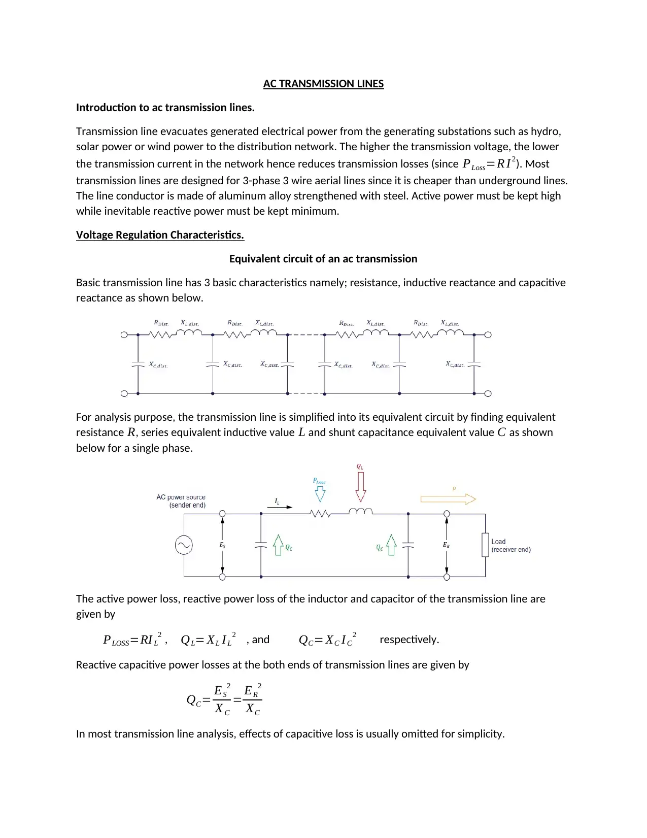
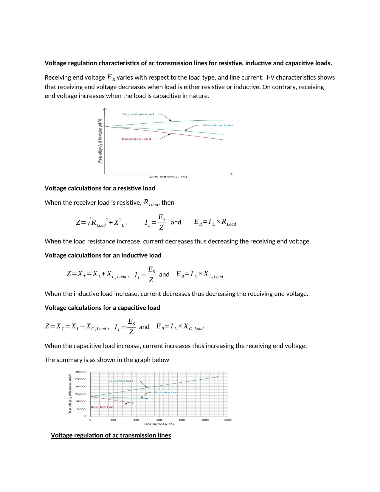
This assignment provides a comprehensive overview of AC transmission lines, detailing their fundamental characteristics and operational principles. It explores the essential aspects of voltage regulation, examining the behavior of transmission lines under resistive, inductive, and capacitive loads. The analysis includes voltage calculations and graphical representations to illustrate voltage variations. Furthermore, the assignment introduces the concept of 3-phase transmission lines, highlighting the impact of inductive reactance. The latter part of the assignment provides an introduction to FACTS devices such as SVC and STATCOM and also covers HVDC systems. The assignment also explains the importance of transmission lines in power systems, focusing on active and reactive power flow. The assignment also covers methods to control active and reactive power flow in interconnected power networks, and the use of regulating autotransformers. The manual includes exercises to help students understand the concepts of power transmission, including the compensation of voltage drops using shunt capacitors and the control of active and reactive power flow in interconnected power networks.
Document Page
AC TRANSMISSION LINES
Introduction to ac transmission lines.
Transmission line evacuates generated electrical power from the generating substations such as hydro,
solar power or wind power to the distribution network. The higher the transmission voltage, the lower
the transmission current in the network hence reduces transmission losses (since PLoss=R I2). Most
transmission lines are designed for 3-phase 3 wire aerial lines since it is cheaper than underground lines.
The line conductor is made of aluminum alloy strengthened with steel. Active power must be kept high
while inevitable reactive power must be kept minimum.
Voltage Regulation Characteristics.
Equivalent circuit of an ac transmission
Basic transmission line has 3 basic characteristics namely; resistance, inductive reactance and capacitive
reactance as shown below.
For analysis purpose, the transmission line is simplified into its equivalent circuit by finding equivalent
resistance R, series equivalent inductive value L and shunt capacitance equivalent value C as shown
below for a single phase.
The active power loss, reactive power loss of the inductor and capacitor of the transmission line are
given by
PLOSS=RI L
2 , QL= XL I L
2 , and QC= XC I C
2 respectively.
Reactive capacitive power losses at the both ends of transmission lines are given by
QC= ES
2
X C
= ER
2
XC
In most transmission line analysis, effects of capacitive loss is usually omitted for simplicity.
tabler-icon-diamond-filled.svg

Secure Best Marks with AI Grader

Need help grading? Try our AI Grader for instant feedback on your assignments.
Document Page
Voltage regulation characteristics of ac transmission lines for resistive, inductive and capacitive loads.
Receiving end voltage ER varies with respect to the load type, and line current. I-V characteristics shows
that receiving end voltage decreases when load is either resistive or inductive. On contrary, receiving
end voltage increases when the load is capacitive in nature.
Voltage calculations for a resistive load
When the receiver load is resistive, RLoad, then
Z= RLoad
2+ X2
L , I L= ES
Z and ER=I L × RLoad
When the load resistance increase, current decreases thus decreasing the receiving end voltage.
Voltage calculations for an inductive load
Z=XT =X L+ XL , Load , IL= ES
Z and ER=I L × X L, Load
When the inductive load increase, current decreases thus decreasing the receiving end voltage.
Voltage calculations for a capacitive load
Z=XT =X LXC , Load , I L= ES
Z and ER=I L × XC , Load
When the capacitive load increase, current increases thus increasing the receiving end voltage.
The summary is as shown in the graph below
Voltage regulation of ac transmission lines
Document Page
Transmission voltage variation indicates the extent of voltage variation in the receiver end ER . Voltage
transmission is determined by the type of the load and inductive reactance. Voltage variation is
determined by the equation below using receiving end no-load and full-load voltages.
Voltage regulation ( % )= { ENLEFL }
EFL
×100 %
Introduction to the 3-phase transmission Line module.
The model characteristics are similar to ac transmission line having inductive reactance. Modification of
the transmission line length on the module is achieved by adjusting inductive reactance chooser. The
higher the inductance adjusted the longer the transmission line.
chevron_up_icon
1 out of 3
circle_padding
hide_on_mobile
zoom_out_icon
logo.png

Your All-in-One AI-Powered Toolkit for Academic Success.

Available 24*7 on WhatsApp / Email

[object Object]