Additive Manufacturing: Processes, Materials, and Applications Report

Verified

Added on  2021/05/31

|6
|1992
|58
Report
AI Summary
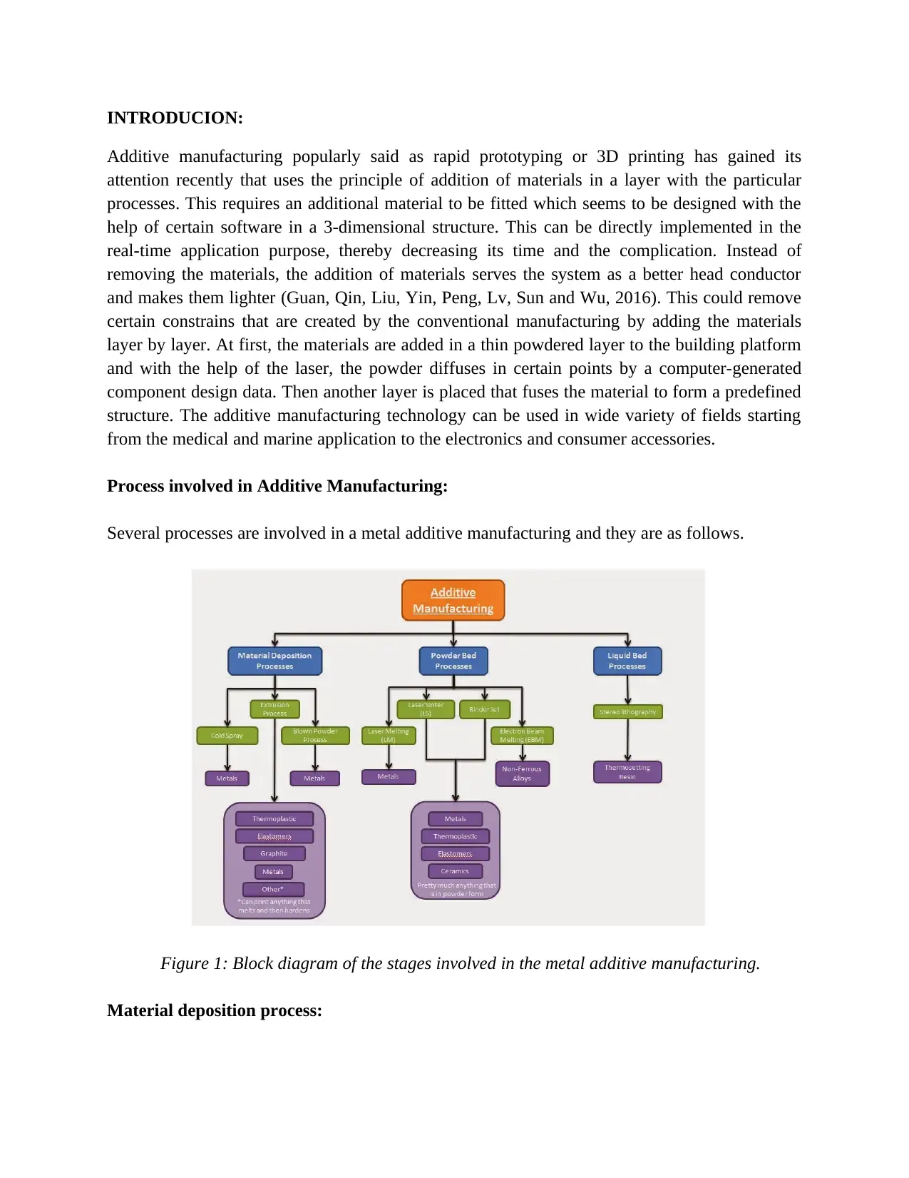
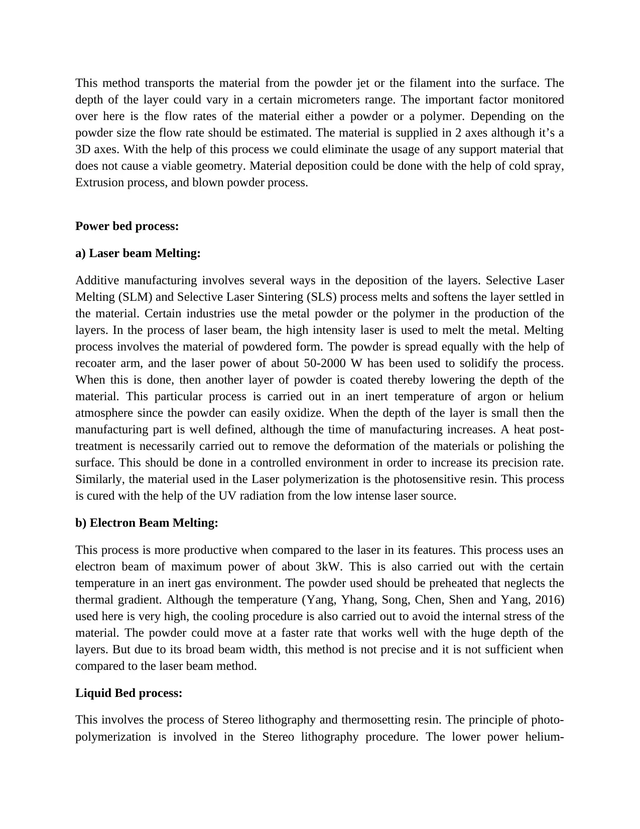
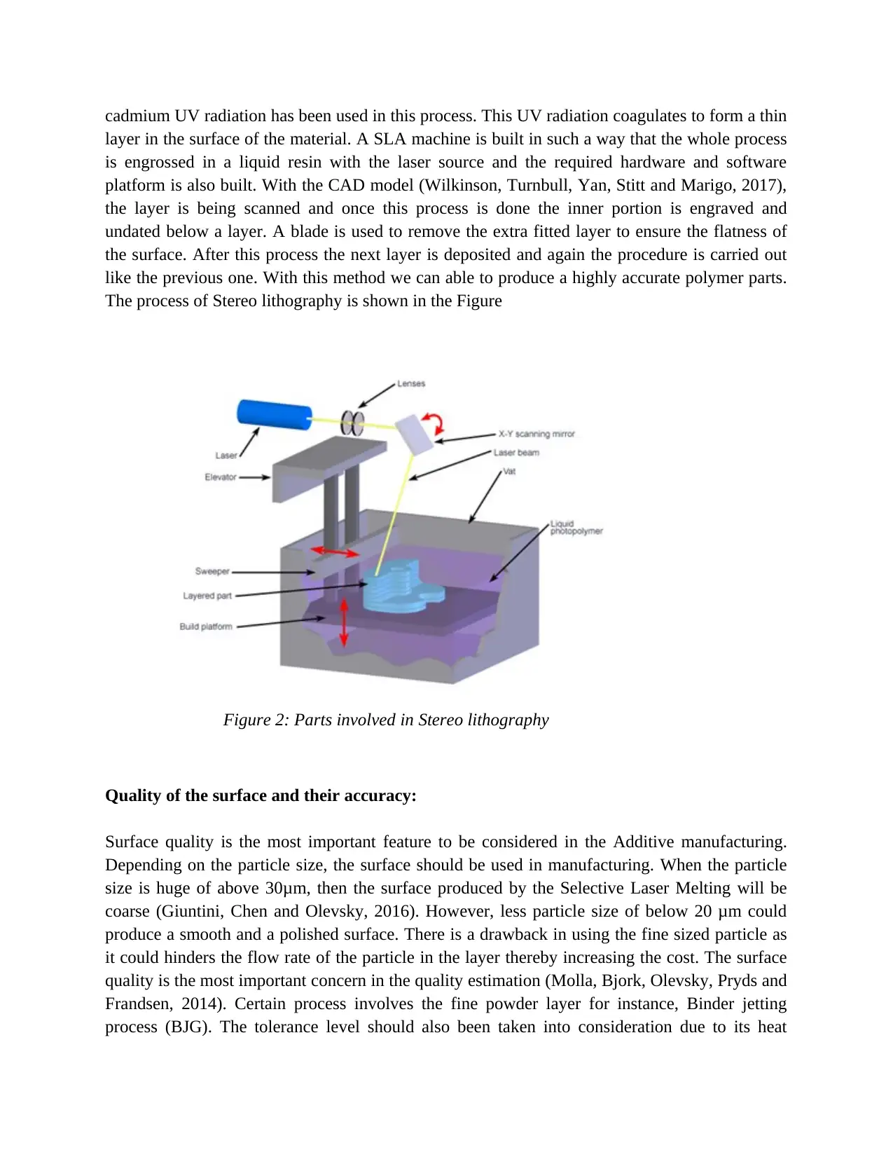
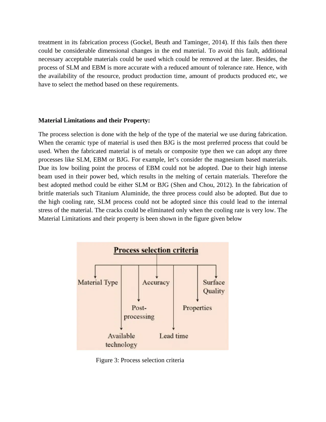
This report provides a comprehensive overview of additive manufacturing, also known as 3D printing. It begins with an introduction to the concept, highlighting its advantages over traditional manufacturing methods, such as the ability to build complex geometries and use lighter materials. The report then delves into the core processes involved in metal additive manufacturing, including material deposition (cold spray, extrusion, blown powder), powder bed processes (laser beam melting, electron beam melting), and liquid bed processes (stereo lithography). Each process is explained in detail, including the specific technologies used, their working principles, and their applications. The report also discusses the importance of surface quality and accuracy, factors that significantly impact the final product. It further addresses material limitations, detailing how the choice of material influences the selection of the manufacturing process. The report concludes by summarizing the key points and emphasizing the importance of considering various process variables and material properties for successful additive manufacturing. References to relevant research papers are also included.
Document Page
INTRODUCION:
Additive manufacturing popularly said as rapid prototyping or 3D printing has gained its
attention recently that uses the principle of addition of materials in a layer with the particular
processes. This requires an additional material to be fitted which seems to be designed with the
help of certain software in a 3-dimensional structure. This can be directly implemented in the
real-time application purpose, thereby decreasing its time and the complication. Instead of
removing the materials, the addition of materials serves the system as a better head conductor
and makes them lighter (Guan, Qin, Liu, Yin, Peng, Lv, Sun and Wu, 2016). This could remove
certain constrains that are created by the conventional manufacturing by adding the materials
layer by layer. At first, the materials are added in a thin powdered layer to the building platform
and with the help of the laser, the powder diffuses in certain points by a computer-generated
component design data. Then another layer is placed that fuses the material to form a predefined
structure. The additive manufacturing technology can be used in wide variety of fields starting
from the medical and marine application to the electronics and consumer accessories.
Process involved in Additive Manufacturing:
Several processes are involved in a metal additive manufacturing and they are as follows.
Figure 1: Block diagram of the stages involved in the metal additive manufacturing.
Material deposition process:
tabler-icon-diamond-filled.svg

Paraphrase This Document

Need a fresh take? Get an instant paraphrase of this document with our AI Paraphraser
Document Page
This method transports the material from the powder jet or the filament into the surface. The
depth of the layer could vary in a certain micrometers range. The important factor monitored
over here is the flow rates of the material either a powder or a polymer. Depending on the
powder size the flow rate should be estimated. The material is supplied in 2 axes although it’s a
3D axes. With the help of this process we could eliminate the usage of any support material that
does not cause a viable geometry. Material deposition could be done with the help of cold spray,
Extrusion process, and blown powder process.
Power bed process:
a) Laser beam Melting:
Additive manufacturing involves several ways in the deposition of the layers. Selective Laser
Melting (SLM) and Selective Laser Sintering (SLS) process melts and softens the layer settled in
the material. Certain industries use the metal powder or the polymer in the production of the
layers. In the process of laser beam, the high intensity laser is used to melt the metal. Melting
process involves the material of powdered form. The powder is spread equally with the help of
recoater arm, and the laser power of about 50-2000 W has been used to solidify the process.
When this is done, then another layer of powder is coated thereby lowering the depth of the
material. This particular process is carried out in an inert temperature of argon or helium
atmosphere since the powder can easily oxidize. When the depth of the layer is small then the
manufacturing part is well defined, although the time of manufacturing increases. A heat post-
treatment is necessarily carried out to remove the deformation of the materials or polishing the
surface. This should be done in a controlled environment in order to increase its precision rate.
Similarly, the material used in the Laser polymerization is the photosensitive resin. This process
is cured with the help of the UV radiation from the low intense laser source.
b) Electron Beam Melting:
This process is more productive when compared to the laser in its features. This process uses an
electron beam of maximum power of about 3kW. This is also carried out with the certain
temperature in an inert gas environment. The powder used should be preheated that neglects the
thermal gradient. Although the temperature (Yang, Yhang, Song, Chen, Shen and Yang, 2016)
used here is very high, the cooling procedure is also carried out to avoid the internal stress of the
material. The powder could move at a faster rate that works well with the huge depth of the
layers. But due to its broad beam width, this method is not precise and it is not sufficient when
compared to the laser beam method.
Liquid Bed process:
This involves the process of Stereo lithography and thermosetting resin. The principle of photo-
polymerization is involved in the Stereo lithography procedure. The lower power helium-
Document Page
cadmium UV radiation has been used in this process. This UV radiation coagulates to form a thin
layer in the surface of the material. A SLA machine is built in such a way that the whole process
is engrossed in a liquid resin with the laser source and the required hardware and software
platform is also built. With the CAD model (Wilkinson, Turnbull, Yan, Stitt and Marigo, 2017),
the layer is being scanned and once this process is done the inner portion is engraved and
undated below a layer. A blade is used to remove the extra fitted layer to ensure the flatness of
the surface. After this process the next layer is deposited and again the procedure is carried out
like the previous one. With this method we can able to produce a highly accurate polymer parts.
The process of Stereo lithography is shown in the Figure
Figure 2: Parts involved in Stereo lithography
Quality of the surface and their accuracy:
Surface quality is the most important feature to be considered in the Additive manufacturing.
Depending on the particle size, the surface should be used in manufacturing. When the particle
size is huge of above 30μm, then the surface produced by the Selective Laser Melting will be
coarse (Giuntini, Chen and Olevsky, 2016). However, less particle size of below 20 μm could
produce a smooth and a polished surface. There is a drawback in using the fine sized particle as
it could hinders the flow rate of the particle in the layer thereby increasing the cost. The surface
quality is the most important concern in the quality estimation (Molla, Bjork, Olevsky, Pryds and
Frandsen, 2014). Certain process involves the fine powder layer for instance, Binder jetting
process (BJG). The tolerance level should also been taken into consideration due to its heat
Document Page
treatment in its fabrication process (Gockel, Beuth and Taminger, 2014). If this fails then there
could be considerable dimensional changes in the end material. To avoid this fault, additional
necessary acceptable materials could be used which could be removed at the later. Besides, the
process of SLM and EBM is more accurate with a reduced amount of tolerance rate. Hence, with
the availability of the resource, product production time, amount of products produced etc, we
have to select the method based on these requirements.
Material Limitations and their Property:
The process selection is done with the help of the type of the material we use during fabrication.
When the ceramic type of material is used then BJG is the most preferred process that could be
used. When the fabricated material is of metals or composite type then we can adopt any three
processes like SLM, EBM or BJG. For example, let’s consider the magnesium based materials.
Due its low boiling point the process of EBM could not be adopted. Due to their high intense
beam used in their power bed, which results in the melting of certain materials. Therefore the
best adopted method could be either SLM or BJG (Shen and Chou, 2012). In the fabrication of
brittle materials such Titanium Aluminide, the three process could also be adopted. But due to
the high cooling rate, SLM process could not be adopted since this could lead to the internal
stress of the material. The cracks could be eliminated only when the cooling rate is very low. The
Material Limitations and their property is been shown in the figure given below
Figure 3: Process selection criteria
tabler-icon-diamond-filled.svg

Paraphrase This Document

Need a fresh take? Get an instant paraphrase of this document with our AI Paraphraser
Document Page
Conclusion:
Thus the working of the manufacturing process has been explained in this report. The
process variables such as the flow rate, Temperature plays a major role in this additive
manufacturing process. The Dimensions and the surface quality should be considered for the
proper end product of the material. Although, there are certain limitations in the process selection
the best method should be adapted depending on the materials used.
References:
Guan, K., Qin, W., Liu, Y., Yin, X.Q., Peng, C., Lv, M., Sun, Q. and Wu, J.Q. (2016). Evolution
of porosity, pore size and permeate flux of ceramic membranes during sintering process. J.
Membr. Sci. 520, 166–175.
Yang, D.L., Yhang, Y., Song, X.Z., Chen, Y.Z., Shen, Z.Q. and Yang, C. (2016) . Effects of
sintering temperature and holding time on porosity and shrinkage of glass tubes. Ceram. Int. 42,
5906–5910.
Wilkinson, S.K., Turnbull, S.A., Yan, Z., Stitt, E.H. and Marigo, M. (2017).A parametric
evaluation of powder flowability using a freeman rheometer through statistical and sensitivity
analysis: A discrete element method (DEM) study. Comput. Chem. Eng. 97, 161–174.
Giuntini, D., Chen, I.-W. and Olevsky, E.A. (2016). Sintering shape distortions controlled by
interface roughness in powder compositions. Scr. Mater. 124, 38–41.
Molla, T.T., Bjork, R., Olevsky, E., Pryds, N. and Frandsen, H.L (2014). Multi-scale modeling
of shape distortions during sintering of bi-layers. Comput. Mater. Sci. 88, 28–36
Vasinonta, A., Beuth, J. and Griffith, M. (2000). Process maps for controlling residual stress and
melt pool size in laser-based SFF processes. In Solid Freeform Fabrication Proceedings,
University of Texas at Austin, Austin, pp 200–208
Gockel, J., Beuth. J.and Taminger, K., (2014). Integrated control of solidification microstructure
and melt pool dimensionsin electron beam wire feed additive manufacturing of Ti-6Al-4V. Addit
Manuf 1–4: 119–126
Shen, N. and Chou, K. (2012). Numerical thermal analysis in electronbeam additive
manufacturing with preheating effects. Proceedings of the 23rd annual international solid
freeform fabrication symposium, pp 774–784
Document Page
Shen, N. & Chou, Y.K. (2012). Thermal modeling of electron beam additive manufacturing
process—powder sintering effects. Proc.the 7th ASME 2012 International Manufacturing
Science andEngineering Conference, pp 287–295
Ardila, L.C., Garciandia, F., Gonzalez-Diaz, J.B., Alvarez, P., Echeverria, A., Petite, M.M. and
Deffley, R. (2014). Ochoa, J. Effect of IN718 recycled powder reuse on properties of parts
manufactured by means of selective laser melting. Phys. Procedia . 56, 99–107.
chevron_up_icon
1 out of 6
circle_padding
hide_on_mobile
zoom_out_icon
[object Object]