Additive Manufacturing Process Optimization Over Traditional: Report
VerifiedAdded on 2023/01/16
|24
|8560
|71
Report
AI Summary
This report delves into the optimization of additive manufacturing (AM) processes compared to traditional manufacturing methods. It begins with an introduction to AM, highlighting its advantages like design flexibility and reduced energy consumption, and rapid prototyping. The report then explores the problem of selecting the right manufacturing equipment. It contrasts AM with traditional methods such as injection molding, CNC machining, plastic forming, and plastic joining, detailing their processes and limitations. Various AM techniques, including powder bed fusion, directed energy deposition, material extrusion, vat photopolymerization, binder jetting, and material jetting, are discussed. The report also includes a case study and concludes by summarizing the key findings and implications of choosing the optimal manufacturing process. The report provides a comparative analysis of manufacturing methodologies and the importance of selecting the most efficient and reliable process.
Optimizing of additive manufacturing process over traditional process &
its procedure
Abstract:
Additive Manufacturing (AM) involves the process of making an object with the model based on
the Computer aided design (CAD) technology. This involves the process of adding layer by layer
to the desired material to make an object gains its perfect shape that seems to be a contrast to
the Subtractive Manufacturing that involves removal of material from the work piece. AM could
also be called by several other names such as additive fabrication, 3-D printing and free-form
fabrication. These methodologies are still booming and finding their application in the field of
manufacturing process. This design technology is found to be highly flexible, robust and less
energy consumption. Rapid prototyping is the process of making a design of 3-Dimensional
model of a product or a part that utilizes the technology of Additive Manufacturing to view that
product or a part in the computer with the three dimensional view before implementing it as
hardware in larger quantities. Due to this there is a ramp increase in the technique that results
from rapid prototyping to the end-product of the user. Certain polymers, metals, composites
and several other materials could be used to print a set of layers that seems to be the
combination of several layers as a range of components. These parts or the product could be
difficult and complex while manufacturing and having a testing and trial normally. An important
note to be considered is that Am technology could not be used in every product and there are
certain restrictions that CM could only be able to progress. These limitations could be pin
pointed as the cost, material property, size and certain other factors that currently limit the AM
applications.
Paraphrase This Document
Need a fresh take? Get an instant paraphrase of this document with our AI Paraphraser
SNO CONTENTS PGNO
1 Introduction 3
2 Background 3
3 Techniques involved in Additive Manufacturing (AM) Process 4
4 Comparison made among traditional and Additive Manufacturing 8
5 Advantages of Additive Manufacturing 11
6 Case study 13
Conclusion 18
References 19
1 Introduction 3
2 Background 3
3 Techniques involved in Additive Manufacturing (AM) Process 4
4 Comparison made among traditional and Additive Manufacturing 8
5 Advantages of Additive Manufacturing 11
6 Case study 13
Conclusion 18
References 19
1. Introduction:
For the past 3 decades, AM has raised an enormous profit in the un-commercialized
technologies that could be worth of about 6 billion Dollars in the year 2016. It is expected to
have an enormous profit of $20 billion by the year 2020. The process of adding layer by layer of
material to form a desired shape using the Computer aided design technique is known as the
Additive Manufacturing (AM) process (Yang et al. 2016). Rapid prototyping was the initially
created methodology that uses the concept of 3D printing, which is referred as AM. Over the
traditional manufacturing process several advantages could be met by the AM since it could
help the engineers and manufacturers to attain their perfect end result. Certain advantages
include customizing mass products, assembly part reduction, and increase in the design
freedom with the effective cost low volume production (Schumacher et al. 2015).
The technologies has been improved with the AM that tends to have an increase in the
sustainability, shorter phase for the product development, lower the cost of manufacturing,
maximizes the demand for the personalized and the customized products and finally the
evolution of new business trends. Several transformations had been carries out in the field of
AM for the past 30 years. Earlier, AM techniques were focused only on the prototypes and the
models (Wilkinson et al. 2017). The maturity of the technology makes the AM to bloom in the
soft as well as rapid tooling. Now-a-days, the products and the end use of the parts are
produced by this technology. Moreover, the opportunities in the field of AM had also leveraged
yet with certain limitations (Giuntini, Chen, and Olevsky, 2016). Certain things we should know
regarding the technology behind AM and when, why and how the AM should be used in those
particular criteria, which should also be known for the effective usage (Shtein, Nadiv, Buzaglo,
Kahil & Regev, 2015).
Problem statement:
The problem occurs in choosing the right manufacturing equipment for the process. Sometimes
the combination of both could also be necessary in certain scenario. At times, based on the
type of production the equipment parts should be chosen to sustain the situation. If the
finished surface should be smooth enough to give sustainability then Additive manufacturing is
not guaranteed. But it could be suitable for high volume and fast production. In early stage of
planning how to decide which manufacturing process falls into efficient and reliable way of
manufacturing is still a question. So what type of manufacturing methodology should be
adapted had been mentioned in the report with the sufficient case studies.
2. Background:
Traditional Manufacturing process works on the principle in producing certain number of
products by holding the reserve in case of unexpected damage or shortages at certain set of
⊘ This is a preview!⊘
Do you want full access?
Subscribe today to unlock all pages.
Trusted by 1+ million students worldwide
periods (Molla, Bjork, Olevsky, Pryds and Frandsen, 2014). There are four main categories
involved in the traditional or commercial technology. These are as follows:
Injection Molding: As the name refers, a plastic material is softened and then it is injected
during the fabrication process inside a mold (Vasinonta, Beuth and Griffith, 2000). This process
comes under a mechanism and the other mechanism involves the removal of the material from
the mold after which it could be cured and solidified. This is highly used in the plastic goods
fabrication process that gives a good finishing surface. The disadvantage among this process is
that the cost of the injection mold is very high and it is not sufficient for the low budget series.
CNC Machining: The material should be machine as a part in any field that involves drilling,
turning or milling (Gockel, Beuth and Taminger, 2014). In this process, the machine is fitted with
the material particle and several tools could be used to remove the material until a desired
format is obtained. Similar to the previous process, this process could not be used for the small
scale applications due to their cost. But the accuracy of this process is very high with the
tolerance rate of 25μm. But the internal features could be fabricated with this process and is
very tedious for the machining process (Shen and Chou, 2012). It is best suited for the engine
components.
Plastic Forming: Several techniques such as pressure forming, thermo forming and vacuum
forming are involved in this process. Each type is specific in their functionality but the process
of heating a plastic sheet and draping it around the mold is similar. Then with the help of the
male plug and the sufficient air pressure could be used to make a shape out of the sheet. The
forming process utilizes thermoplastics virtually and only one side of the plastic could be
modulated by this process (Shen and Chou, 2012). Compared to the above two process, the
installation and byproduct costs are very low.
Plastic Joining: This process involves in combining the semi finished parts. Welding, adhesive
bonding and fastening are the process involved here (Ardila, 2014). The incorporation of latches
along with the snap and hinges that fits into the design part or with the screws and bolts as the
external fasteners comes under the process of fastening. Epoxy is said to be an adhesive that
could be used in joining the parts together involves under the category of adhesive bonding.
Finally, welding is the stage that involves the application of heat under sufficient pressure to
combine the material together. The semi- finished parts and their property plays a vital role in
choosing the sufficient technique. However, this process is quite time consuming and the cost
for the labor charges seems to be very high.
3. Techniques involved in Additive Manufacturing (AM) Process:
Certain Industrial companies uses AM technology in their commercial markets located in
several countries such as Germany, Sweden, United States, United Kingdom, etc (Buffa,
Paraphrase This Document
Need a fresh take? Get an instant paraphrase of this document with our AI Paraphraser
Campanella, Fratini and Micari, 2016). According to the American Society for Testing and
materials (ASTM) F42 Committee, Am could be classified into several broad categories as
follows:
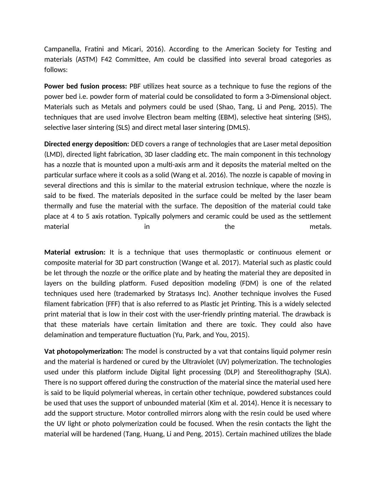
Power bed fusion process: PBF utilizes heat source as a technique to fuse the regions of the
power bed i.e. powder form of material could be consolidated to form a 3-Dimensional object.
Materials such as Metals and polymers could be used (Shao, Tang, Li and Peng, 2015). The
techniques that are used involve Electron beam melting (EBM), selective heat sintering (SHS),
selective laser sintering (SLS) and direct metal laser sintering (DMLS).
Directed energy deposition: DED covers a range of technologies that are Laser metal deposition
(LMD), directed light fabrication, 3D laser cladding etc. The main component in this technology
has a nozzle that is mounted upon a multi-axis arm and it deposits the material melted on the
particular surface where it cools as a solid (Wang et al. 2016). The nozzle is capable of moving in
several directions and this is similar to the material extrusion technique, where the nozzle is
said to be fixed. The materials deposited in the surface could be melted by the laser beam
thermally and fuse the material with the surface. The deposition of the material could take
place at 4 to 5 axis rotation. Typically polymers and ceramic could be used as the settlement
material in the metals.
Material extrusion: It is a technique that uses thermoplastic or continuous element or
composite material for 3D part construction (Wange et al. 2017). Material such as plastic could
be let through the nozzle or the orifice plate and by heating the material they are deposited in
layers on the building platform. Fused deposition modeling (FDM) is one of the related
techniques used here (trademarked by Stratasys Inc). Another technique involves the Fused
filament fabrication (FFF) that is also referred to as Plastic jet Printing. This is a widely selected
print material that is low in their cost with the user-friendly printing material. The drawback is
that these materials have certain limitation and there are toxic. They could also have
delamination and temperature fluctuation (Yu, Park, and You, 2015).
Vat photopolymerization: The model is constructed by a vat that contains liquid polymer resin
and the material is hardened or cured by the Ultraviolet (UV) polymerization. The technologies
used under this platform include Digital light processing (DLP) and Stereolithography (SLA).
There is no support offered during the construction of the material since the material used here
is said to be liquid polymerial whereas, in certain other technique, powdered substances could
be used that uses the support of unbounded material (Kim et al. 2014). Hence it is necessary to
add the support structure. Motor controlled mirrors along with the resin could be used where
the UV light or photo polymerization could be focused. When the resin contacts the light the
material will be hardened (Tang, Huang, Li and Peng, 2015). Certain machined utilizes the blade
materials (ASTM) F42 Committee, Am could be classified into several broad categories as
follows:
Power bed fusion process: PBF utilizes heat source as a technique to fuse the regions of the
power bed i.e. powder form of material could be consolidated to form a 3-Dimensional object.
Materials such as Metals and polymers could be used (Shao, Tang, Li and Peng, 2015). The
techniques that are used involve Electron beam melting (EBM), selective heat sintering (SHS),
selective laser sintering (SLS) and direct metal laser sintering (DMLS).
Directed energy deposition: DED covers a range of technologies that are Laser metal deposition
(LMD), directed light fabrication, 3D laser cladding etc. The main component in this technology
has a nozzle that is mounted upon a multi-axis arm and it deposits the material melted on the
particular surface where it cools as a solid (Wang et al. 2016). The nozzle is capable of moving in
several directions and this is similar to the material extrusion technique, where the nozzle is
said to be fixed. The materials deposited in the surface could be melted by the laser beam
thermally and fuse the material with the surface. The deposition of the material could take
place at 4 to 5 axis rotation. Typically polymers and ceramic could be used as the settlement
material in the metals.
Material extrusion: It is a technique that uses thermoplastic or continuous element or
composite material for 3D part construction (Wange et al. 2017). Material such as plastic could
be let through the nozzle or the orifice plate and by heating the material they are deposited in
layers on the building platform. Fused deposition modeling (FDM) is one of the related
techniques used here (trademarked by Stratasys Inc). Another technique involves the Fused
filament fabrication (FFF) that is also referred to as Plastic jet Printing. This is a widely selected
print material that is low in their cost with the user-friendly printing material. The drawback is
that these materials have certain limitation and there are toxic. They could also have
delamination and temperature fluctuation (Yu, Park, and You, 2015).
Vat photopolymerization: The model is constructed by a vat that contains liquid polymer resin
and the material is hardened or cured by the Ultraviolet (UV) polymerization. The technologies
used under this platform include Digital light processing (DLP) and Stereolithography (SLA).
There is no support offered during the construction of the material since the material used here
is said to be liquid polymerial whereas, in certain other technique, powdered substances could
be used that uses the support of unbounded material (Kim et al. 2014). Hence it is necessary to
add the support structure. Motor controlled mirrors along with the resin could be used where
the UV light or photo polymerization could be focused. When the resin contacts the light the
material will be hardened (Tang, Huang, Li and Peng, 2015). Certain machined utilizes the blade
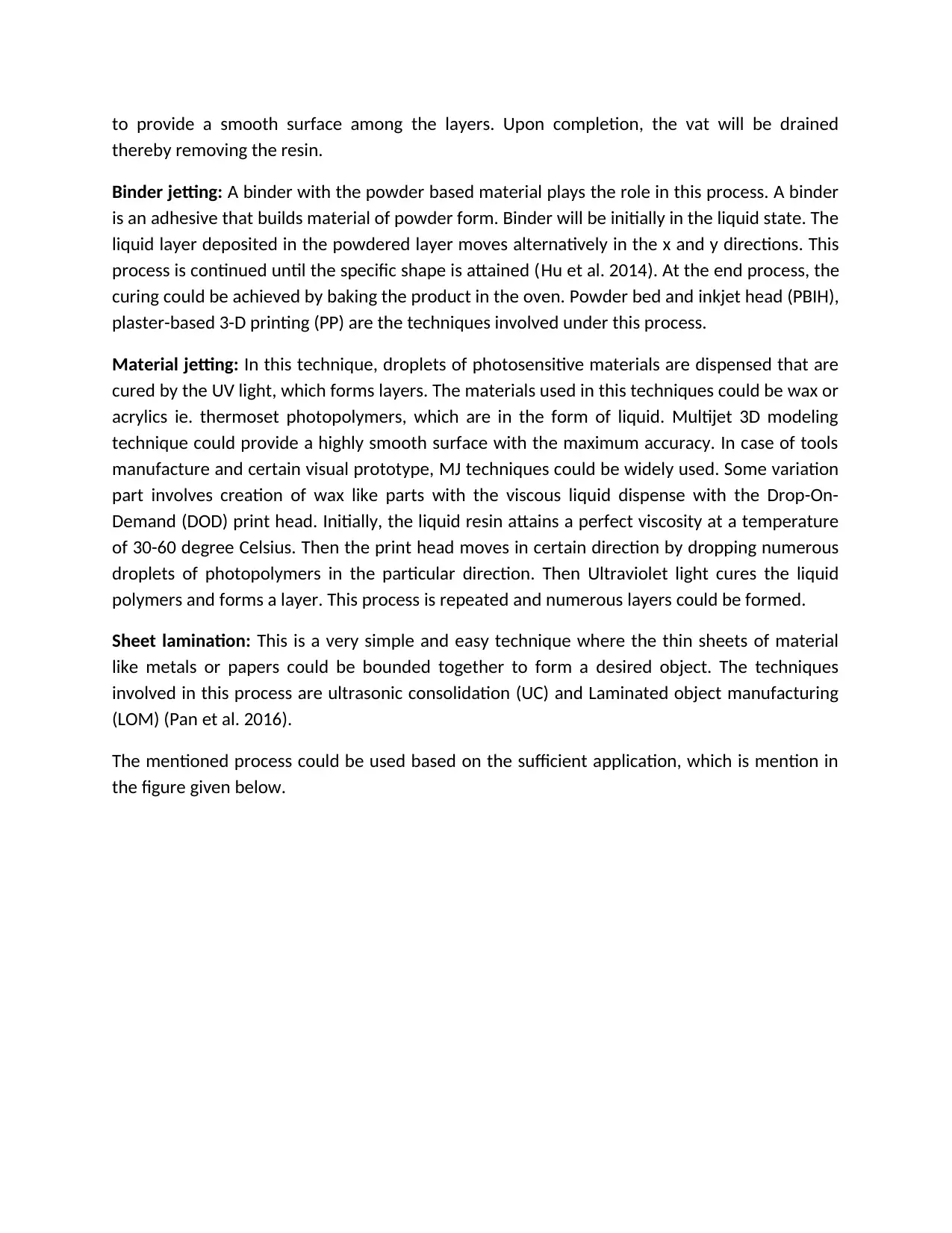
to provide a smooth surface among the layers. Upon completion, the vat will be drained
thereby removing the resin.
Binder jetting: A binder with the powder based material plays the role in this process. A binder
is an adhesive that builds material of powder form. Binder will be initially in the liquid state. The
liquid layer deposited in the powdered layer moves alternatively in the x and y directions. This
process is continued until the specific shape is attained (Hu et al. 2014). At the end process, the
curing could be achieved by baking the product in the oven. Powder bed and inkjet head (PBIH),
plaster-based 3-D printing (PP) are the techniques involved under this process.
Material jetting: In this technique, droplets of photosensitive materials are dispensed that are
cured by the UV light, which forms layers. The materials used in this techniques could be wax or
acrylics ie. thermoset photopolymers, which are in the form of liquid. Multijet 3D modeling
technique could provide a highly smooth surface with the maximum accuracy. In case of tools
manufacture and certain visual prototype, MJ techniques could be widely used. Some variation
part involves creation of wax like parts with the viscous liquid dispense with the Drop-On-
Demand (DOD) print head. Initially, the liquid resin attains a perfect viscosity at a temperature
of 30-60 degree Celsius. Then the print head moves in certain direction by dropping numerous
droplets of photopolymers in the particular direction. Then Ultraviolet light cures the liquid
polymers and forms a layer. This process is repeated and numerous layers could be formed.
Sheet lamination: This is a very simple and easy technique where the thin sheets of material
like metals or papers could be bounded together to form a desired object. The techniques
involved in this process are ultrasonic consolidation (UC) and Laminated object manufacturing
(LOM) (Pan et al. 2016).
The mentioned process could be used based on the sufficient application, which is mention in
the figure given below.
⊘ This is a preview!⊘
Do you want full access?
Subscribe today to unlock all pages.
Trusted by 1+ million students worldwide
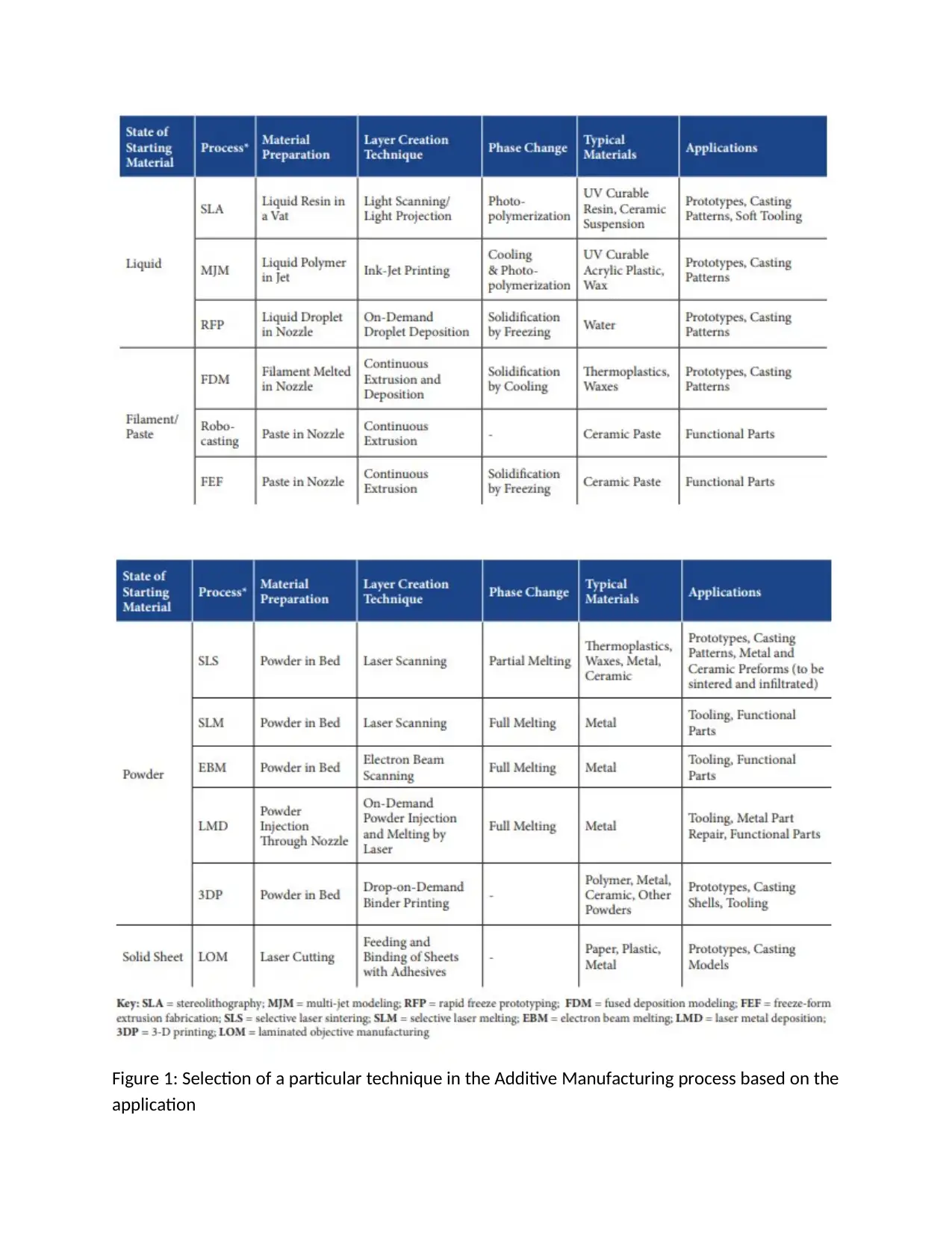
Figure 1: Selection of a particular technique in the Additive Manufacturing process based on the
application
application
Paraphrase This Document
Need a fresh take? Get an instant paraphrase of this document with our AI Paraphraser
(Source: Quadrennial Technology Review, 2015)
Sustainability is always said to be a concern factor in the AM technology. Few studies had
performed a potential effect on the energy efficiency and environmental factors that are
impacted by the AM technology. There is always a concern of material wastage and energy
consumption evolving around the AM technology. For instance, Fused deposition modeling
leaves out the waste of support structure during its process. Stereolithography and Selective
laser sintering are the certain laser bed process that sinters the part from the large material bed
leaving behind a huge deposit waste of un-sintered material (Drozdenko et al. 2016). On the
other hand, the intensive energy consuming process involves material extrusion, raw material
deposition, laser scanning, heating and cooling process of the bed etc.
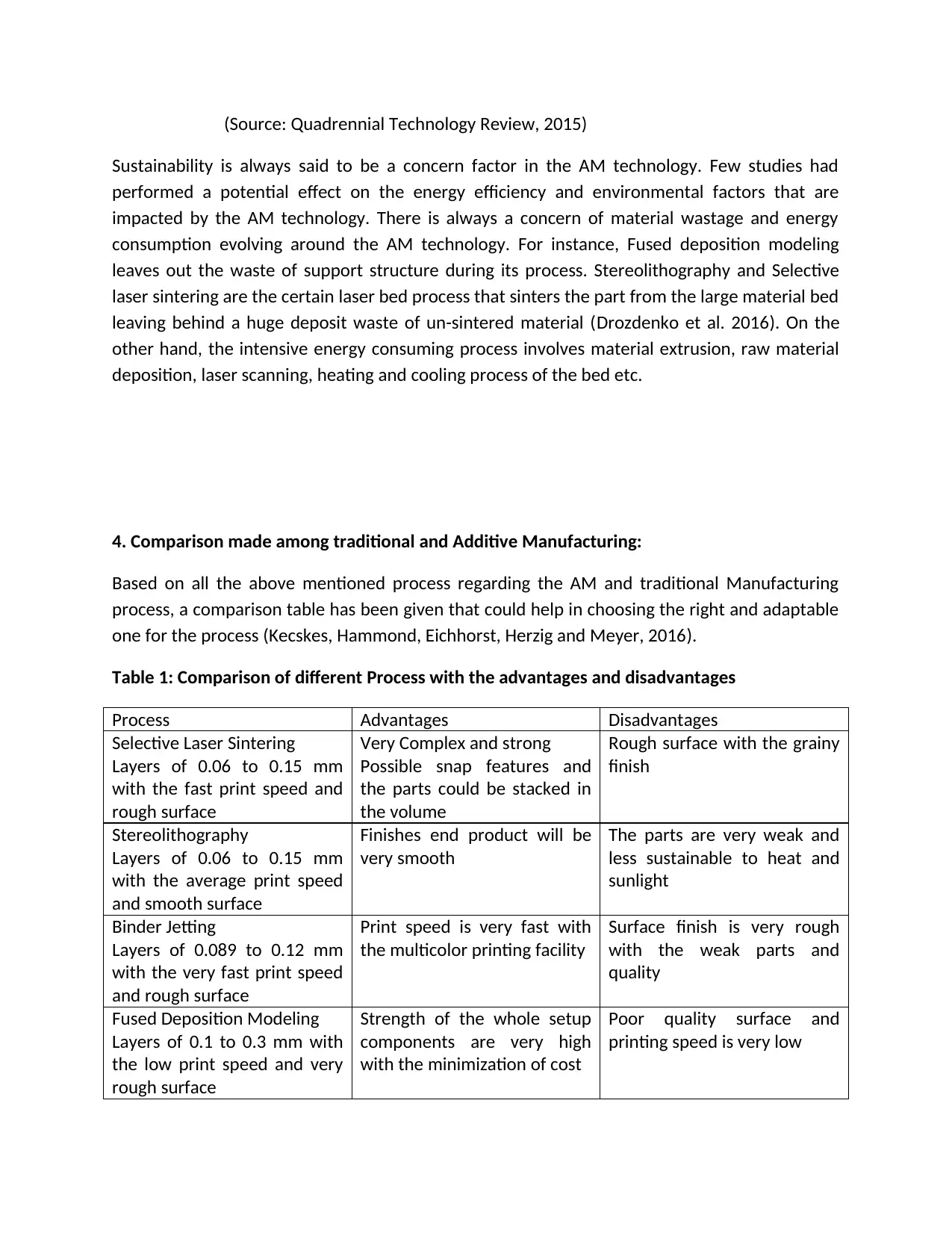
4. Comparison made among traditional and Additive Manufacturing:
Based on all the above mentioned process regarding the AM and traditional Manufacturing
process, a comparison table has been given that could help in choosing the right and adaptable
one for the process (Kecskes, Hammond, Eichhorst, Herzig and Meyer, 2016).
Table 1: Comparison of different Process with the advantages and disadvantages
Process Advantages Disadvantages
Selective Laser Sintering
Layers of 0.06 to 0.15 mm
with the fast print speed and
rough surface
Very Complex and strong
Possible snap features and
the parts could be stacked in
the volume
Rough surface with the grainy
finish
Stereolithography
Layers of 0.06 to 0.15 mm
with the average print speed
and smooth surface
Finishes end product will be
very smooth
The parts are very weak and
less sustainable to heat and
sunlight
Binder Jetting
Layers of 0.089 to 0.12 mm
with the very fast print speed
and rough surface
Print speed is very fast with
the multicolor printing facility
Surface finish is very rough
with the weak parts and
quality
Fused Deposition Modeling
Layers of 0.1 to 0.3 mm with
the low print speed and very
rough surface
Strength of the whole setup
components are very high
with the minimization of cost
Poor quality surface and
printing speed is very low
Sustainability is always said to be a concern factor in the AM technology. Few studies had
performed a potential effect on the energy efficiency and environmental factors that are
impacted by the AM technology. There is always a concern of material wastage and energy
consumption evolving around the AM technology. For instance, Fused deposition modeling
leaves out the waste of support structure during its process. Stereolithography and Selective
laser sintering are the certain laser bed process that sinters the part from the large material bed
leaving behind a huge deposit waste of un-sintered material (Drozdenko et al. 2016). On the
other hand, the intensive energy consuming process involves material extrusion, raw material
deposition, laser scanning, heating and cooling process of the bed etc.
4. Comparison made among traditional and Additive Manufacturing:
Based on all the above mentioned process regarding the AM and traditional Manufacturing
process, a comparison table has been given that could help in choosing the right and adaptable
one for the process (Kecskes, Hammond, Eichhorst, Herzig and Meyer, 2016).
Table 1: Comparison of different Process with the advantages and disadvantages
Process Advantages Disadvantages
Selective Laser Sintering
Layers of 0.06 to 0.15 mm
with the fast print speed and
rough surface
Very Complex and strong
Possible snap features and
the parts could be stacked in
the volume
Rough surface with the grainy
finish
Stereolithography
Layers of 0.06 to 0.15 mm
with the average print speed
and smooth surface
Finishes end product will be
very smooth
The parts are very weak and
less sustainable to heat and
sunlight
Binder Jetting
Layers of 0.089 to 0.12 mm
with the very fast print speed
and rough surface
Print speed is very fast with
the multicolor printing facility
Surface finish is very rough
with the weak parts and
quality
Fused Deposition Modeling
Layers of 0.1 to 0.3 mm with
the low print speed and very
rough surface
Strength of the whole setup
components are very high
with the minimization of cost
Poor quality surface and
printing speed is very low
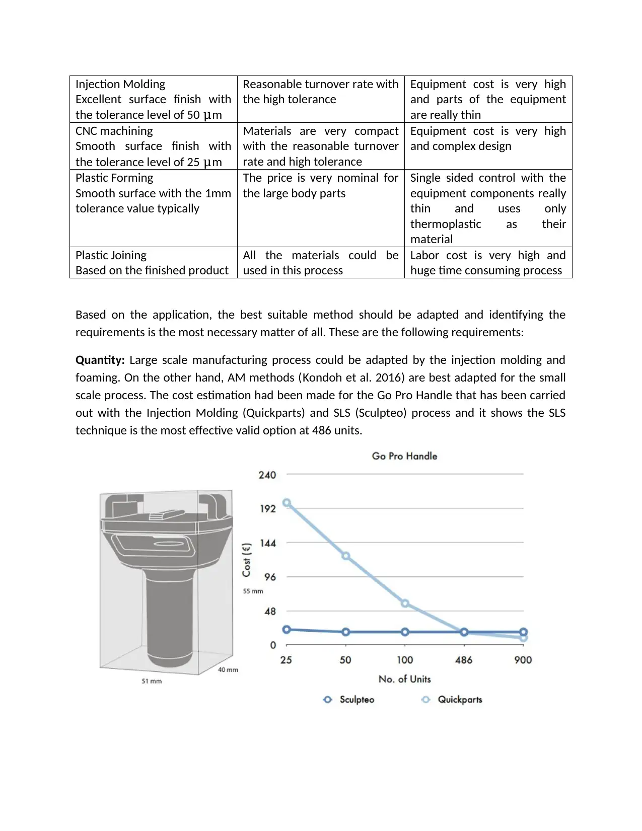
Injection Molding
Excellent surface finish with
the tolerance level of 50 μm
Reasonable turnover rate with
the high tolerance
Equipment cost is very high
and parts of the equipment
are really thin
CNC machining
Smooth surface finish with
the tolerance level of 25 μm
Materials are very compact
with the reasonable turnover
rate and high tolerance
Equipment cost is very high
and complex design
Plastic Forming
Smooth surface with the 1mm
tolerance value typically
The price is very nominal for
the large body parts
Single sided control with the
equipment components really
thin and uses only
thermoplastic as their
material
Plastic Joining
Based on the finished product
All the materials could be
used in this process
Labor cost is very high and
huge time consuming process
Based on the application, the best suitable method should be adapted and identifying the
requirements is the most necessary matter of all. These are the following requirements:
Quantity: Large scale manufacturing process could be adapted by the injection molding and
foaming. On the other hand, AM methods (Kondoh et al. 2016) are best adapted for the small
scale process. The cost estimation had been made for the Go Pro Handle that has been carried
out with the Injection Molding (Quickparts) and SLS (Sculpteo) process and it shows the SLS
technique is the most effective valid option at 486 units.
⊘ This is a preview!⊘
Do you want full access?
Subscribe today to unlock all pages.
Trusted by 1+ million students worldwide
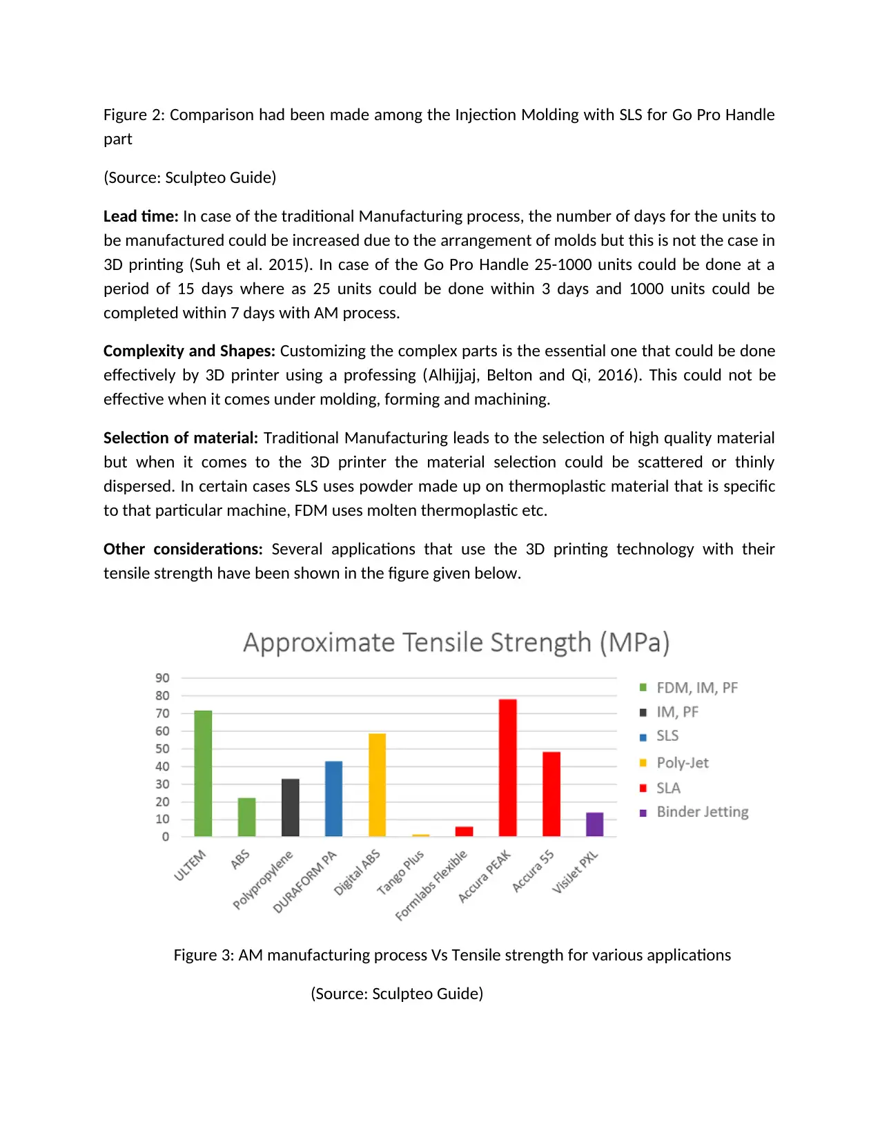
Figure 2: Comparison had been made among the Injection Molding with SLS for Go Pro Handle
part
(Source: Sculpteo Guide)
Lead time: In case of the traditional Manufacturing process, the number of days for the units to
be manufactured could be increased due to the arrangement of molds but this is not the case in
3D printing (Suh et al. 2015). In case of the Go Pro Handle 25-1000 units could be done at a
period of 15 days where as 25 units could be done within 3 days and 1000 units could be
completed within 7 days with AM process.
Complexity and Shapes: Customizing the complex parts is the essential one that could be done
effectively by 3D printer using a professing (Alhijjaj, Belton and Qi, 2016). This could not be
effective when it comes under molding, forming and machining.
Selection of material: Traditional Manufacturing leads to the selection of high quality material
but when it comes to the 3D printer the material selection could be scattered or thinly
dispersed. In certain cases SLS uses powder made up on thermoplastic material that is specific
to that particular machine, FDM uses molten thermoplastic etc.
Other considerations: Several applications that use the 3D printing technology with their
tensile strength have been shown in the figure given below.
Figure 3: AM manufacturing process Vs Tensile strength for various applications
(Source: Sculpteo Guide)
Paraphrase This Document
Need a fresh take? Get an instant paraphrase of this document with our AI Paraphraser
As seen in the chart, high strength plastic could be used as the material in the ABS and ULTEM
with the process of FDM / FFF (Ambrosi, Pumera, 2016). But certain type of materials could not
be processed by the SLA and poly-jet since they requires photo-curable resins. Due to this a
replacement had been found for the engineering plastic, which is nothing but exhibiting the
elastomeric properties. In the chart shown Tango Plus and Formlabs Flexible utilize them but an
important factor is that these resins are irresistible to heat hence it should be protected from
the sunlight.
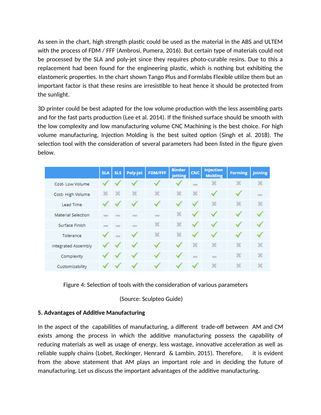
3D printer could be best adapted for the low volume production with the less assembling parts
and for the fast parts production (Lee et al. 2014). If the finished surface should be smooth with
the low complexity and low manufacturing volume CNC Machining is the best choice. For high
volume manufacturing, Injection Molding is the best suited option (Singh et al. 2018). The
selection tool with the consideration of several parameters had been listed in the figure given
below.
Figure 4: Selection of tools with the consideration of various parameters
(Source: Sculpteo Guide)
5. Advantages of Additive Manufacturing
In the aspect of the capabilities of manufacturing, a different trade-off between AM and CM
exists among the process in which the additive manufacturing possess the capability of
reducing materials as well as usage of energy, less wastage, innovative acceleration as well as
reliable supply chains (Lobet, Reckinger, Henrard & Lambin, 2015). Therefore, it is evident
from the above statement that AM plays an important role and in deciding the future of
manufacturing. Let us discuss the important advantages of the additive manufacturing.
with the process of FDM / FFF (Ambrosi, Pumera, 2016). But certain type of materials could not
be processed by the SLA and poly-jet since they requires photo-curable resins. Due to this a
replacement had been found for the engineering plastic, which is nothing but exhibiting the
elastomeric properties. In the chart shown Tango Plus and Formlabs Flexible utilize them but an
important factor is that these resins are irresistible to heat hence it should be protected from
the sunlight.
3D printer could be best adapted for the low volume production with the less assembling parts
and for the fast parts production (Lee et al. 2014). If the finished surface should be smooth with
the low complexity and low manufacturing volume CNC Machining is the best choice. For high
volume manufacturing, Injection Molding is the best suited option (Singh et al. 2018). The
selection tool with the consideration of several parameters had been listed in the figure given
below.
Figure 4: Selection of tools with the consideration of various parameters
(Source: Sculpteo Guide)
5. Advantages of Additive Manufacturing
In the aspect of the capabilities of manufacturing, a different trade-off between AM and CM
exists among the process in which the additive manufacturing possess the capability of
reducing materials as well as usage of energy, less wastage, innovative acceleration as well as
reliable supply chains (Lobet, Reckinger, Henrard & Lambin, 2015). Therefore, it is evident
from the above statement that AM plays an important role and in deciding the future of
manufacturing. Let us discuss the important advantages of the additive manufacturing.
Creativity: By integrating CM processes, the AM leads to innovative frameworks along with its
effective geometrics which can be easily developed during the course of the manufacturing
process (Sitthi-Amorn et al. 2015) (Song et al. 2014). This type of innovation enhances the
performance, environmental friendly as well as cost effective solution in engineering and
product application, for instance, 9 AM systems which are programmed to accommodate
properties inside a component which enhances the performance by employing conventional
processing (Lozano et al. 2015).
Design products with fewer, more complex parts: The unique ability to create components
using few but complex parts is a major advantage of AM (Murray et al. 2015). This feature is so
unique that it only exists in AM which upgrades the performance at a system level excluding the
manufacturability present at the subsystem level. In-order to reduce the overhead association
concerning the production planning as well as control and documentation, a minimum number
of parts in an assembly is considered (MacDonald, & Wicker, 2016). By employed minimum
number of parts, less labour time needed to manufacture the product and the “footprint” of
the assembly line are gained which in return lessen the overall reduction in manufacturing
expenses.
Preserve energy by obviating production process: Lower energy consumption is achieved by
deploying AM which results in less material usage (Macdonald et al. 2014), encouraging recycle
of by-products, and manufacturing lighter products.
Decrease in wastage: Creating objects layer by layer reduces materials needs and less human
error in production as well as the costs by 96% unlike the traditional manufacturing working
that increase usage of material (McMenamin et al. 2014). Eventually, “cradle-togate” present in
the environmental footprints of parts manufacturing through rejection of the tools diminishes
as well as material scrap existing in the CM processes.
Faster deployment to industry: As soon as the Standard Tessellation Language [STL] file is
created by employing 3-D digital description (3-D scanning or 3-D imaging ) to the parts, the
need for more expensive, in-effective part tooling as well as prototype fabrication is achieved
(Tekinalp et al. 2014).
Less weight: With less material, complex shapes applied to the specification of the conventional
parts with the help of the AM can be achieved (Melnikova, Ehrmann & Finsterbusch, 2014).
AM enables rapid response to markets: With the ability to build fresh production options
outside of factories, for instance mobile units that can be located close to the source of local
materials, thereby increasing the agility of manufacturing (Melocchi et al. 2016). AM does not
include high cost tools unlike in traditional manufacturing which leads to longer production
process and slow production rate when there is need for high volume of production (Mitsouras
⊘ This is a preview!⊘
Do you want full access?
Subscribe today to unlock all pages.
Trusted by 1+ million students worldwide
1 out of 24
Related Documents


Your All-in-One AI-Powered Toolkit for Academic Success.
+13062052269
info@desklib.com
Available 24*7 on WhatsApp / Email
![[object Object]](/_next/static/media/star-bottom.7253800d.svg)
Unlock your academic potential
Copyright © 2020–2026 A2Z Services. All Rights Reserved. Developed and managed by ZUCOL.