Advanced Computer Aided Engineering Project: Structural Analysis

Verified

Added on  2020/02/24

|9
|421
|109
Project
AI Summary
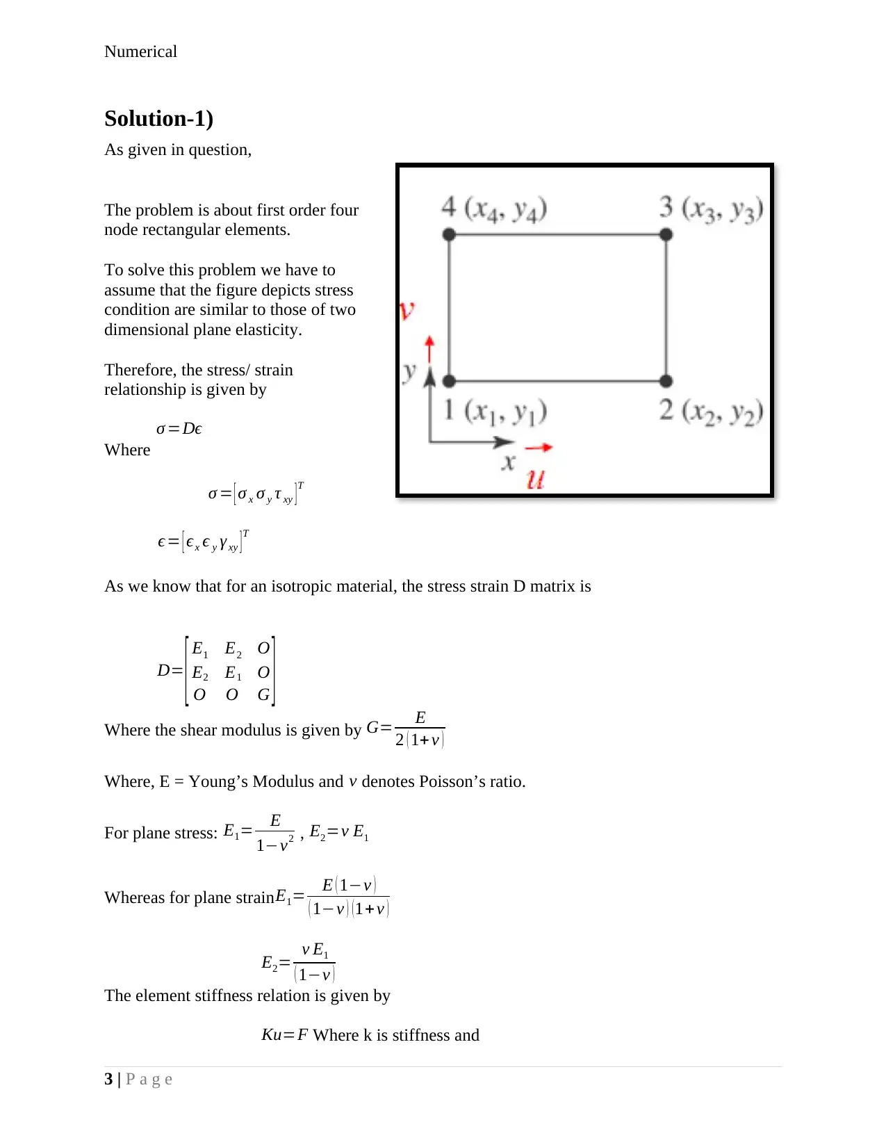
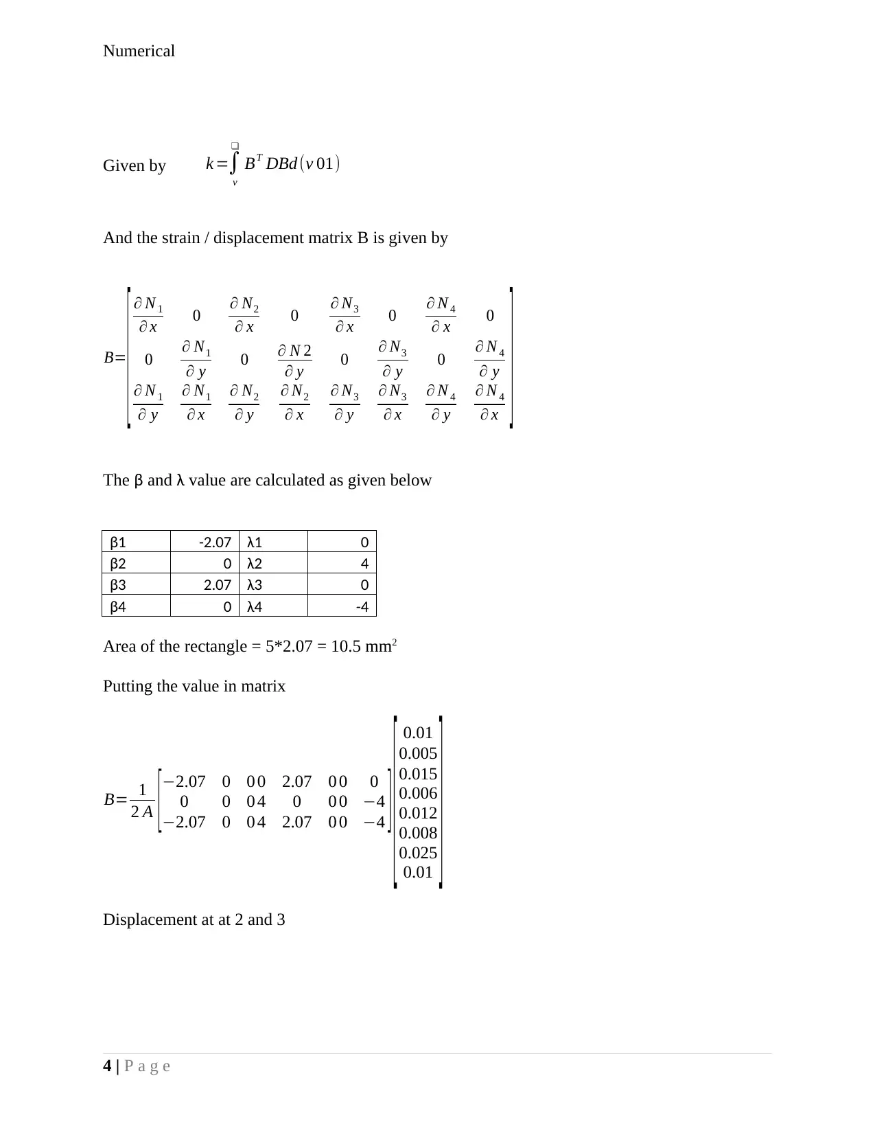
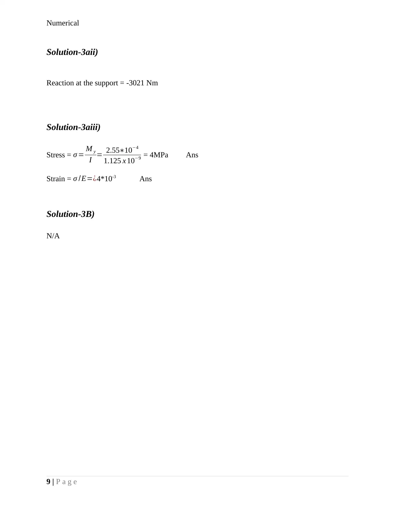
This project focuses on the numerical analysis of structural elements, specifically addressing stress, strain, and displacement calculations. It involves the application of finite element analysis principles to solve problems related to two-dimensional plane elasticity and the behavior of structural components under load. The solution outlines the steps to calculate the element stiffness matrix, strain/displacement matrix, and nodal displacements. It includes calculations for bending moments, reactions at supports, and stress/strain values. Furthermore, the project incorporates the analysis of axial forces and bending moments within a structural element, demonstrating how to compute key parameters such as inertia, nodal displacement, and stress. The project provides detailed solutions, including formulas, calculations, and final answers for various scenarios, making it a valuable resource for students studying mechanical engineering and related fields. The document is available on Desklib, a platform offering AI-based study tools for students.
Document Page
Numerical
1 | P a g e
Advanced Computer Aided
Engineering
tabler-icon-diamond-filled.svg

Secure Best Marks with AI Grader

Need help grading? Try our AI Grader for instant feedback on your assignments.
Document Page
Numerical
Contents
Solution-1).......................................................................................................................................3
Solution-2).......................................................................................................................................5
Solution-3).......................................................................................................................................7
Solution-3a1)...............................................................................................................................7
Solution-3aii)...............................................................................................................................8
Solution-3aiii)..............................................................................................................................8
Solution-3B)................................................................................................................................9
2 | P a g e
Document Page
Numerical
Solution-1)
As given in question,
The problem is about first order four
node rectangular elements.
To solve this problem we have to
assume that the figure depicts stress
condition are similar to those of two
dimensional plane elasticity.
Therefore, the stress/ strain
relationship is given by
σ =
Where
σ = [ σ x σ y τ xy ] T
ϵ= [ ϵx ϵ y γ xy ]T
As we know that for an isotropic material, the stress strain D matrix is
D= [ E1 E2 O
E2 E1 O
O O G ]
Where the shear modulus is given by G= E
2 ( 1+ ν )
Where, E = Young’s Modulus and ν denotes Poisson’s ratio.
For plane stress: E1= E
1ν2 , E2=ν E1
Whereas for plane strainE1= E ( 1ν )
( 1ν ) (1+ ν )
E2= ν E1
( 1ν )
The element stiffness relation is given by
Ku=F Where k is stiffness and
3 | P a g e
Document Page
Numerical
Given by k =
ν

BT DBd (v 01)
And the strain / displacement matrix B is given by
B=
[ N 1
x 0 N2
x 0 N3
x 0 N 4
x 0
0 N1
y 0 N 2
y 0 N3
y 0 N 4
y
N 1
y
N1
x
N2
y
N2
x
N3
y
N3
x
N 4
y
N 4
x
]
The β and λ value are calculated as given below
β1 -2.07 λ1 0
β2 0 λ2 4
β3 2.07 λ3 0
β4 0 λ4 -4
Area of the rectangle = 5*2.07 = 10.5 mm2
Putting the value in matrix
B= 1
2 A [
2.07 0 0
0 0 0
2.07 0 0
0 2.07 0
4 0 0
4 2.07 0
0 0
0 4
0 4 ] [ 0.01
0.005
0.015
0.006
0.012
0.008
0.025
0.01
]Displacement at at 2 and 3
4 | P a g e
tabler-icon-diamond-filled.svg

Secure Best Marks with AI Grader

Need help grading? Try our AI Grader for instant feedback on your assignments.
Document Page
Numerical
[u2 x
u2 y
u3 x
u3 x
]= 1
2 A [2.07 0 0
0 0 0
2.07 0 0
0 2.07 0
4 0 0
4 2.07 0
0 0
0 4
0 4
0 1 4 0 3 2.074 0 ] [ 0.01
0.005
0.015
0.006
0.012
0.008
0.025
0.01
]
[ u2 x
u2 y
u3 x
u3 x
]= 1
210.5 [ 0.00414
0.016
0.01186
0.01756 ]
[u2 x
u2 y
u3 x
u3 x
]=
[ 0.00020
0.00076
0.00056
0.000084 ]
Ans
Solution-2)
As given in question,
5 | P a g e
Document Page
Numerical
T n=20+0.7 N /mm2
We can see that load is acting on 2 and 3 point
X2 = 8 mm, x3 = 5 mm, y2 = 0 mm, y3 = 4 mm
l23= (x2x3 )2+( y2 y3 )2
l23= (85)2 +(40)2= 9+16=5
Suppose, C= 40
l23
=0.8
S= 85
5 =0.6
Traction along x axis
T x= ρC=(20+0.07)0.8=16.56 Ans
Traction along y axis
T y=ρS=(20+0.07)0.6=12.042 Ans
Solving a and b
a= 2 x2 +x3
6 = 21
6 = 16+5
6 =3.5
b= 2 x3 + x2
6 = 10+8
6 = 18
6 =3 Ans
Now I have to calculate force matrix for 2 and 3
T =2 Π l12 [ a T x a T y b T x b T y ] T
a T x=3.5 ( 20+0.07 ) 0.8=56.196
a T y=3.5 (20+0.07 ) 0.6=42.147
6 | P a g e
Document Page
Numerical
b T x=3 (20+ 0.07 ) 0.8=48.168
b T y=3 ( 20+ 0.07 ) 0.6=36.126
2 Π l12=23.145=31.416
Therefore force matrix can be given as
[ T ] =
[ 0
0
1753.14
1314.86
1502.68
1127.02
0
0
] Q1
Q2
Q3
Q4
Q5
Q6
Q7
Q8
Q1=0, Q2=0, Q3=1753.14, Q4 =1314.86, Q5=1502.68, Q6=1127.02
Q7=0, Q8=0
Hence, Q1 to Q8 are the respective point Ans
Solution-3)
As given in question, Net axial force = 10+0.07 – 10-0.07 = 0
Net bending moment = (10.07) x 103 x 30 x 10-2 Nm = 3021 Nm
M = 3.021 KNM or 3021 Nm
7 | P a g e
tabler-icon-diamond-filled.svg

Paraphrase This Document

Need a fresh take? Get an instant paraphrase of this document with our AI Paraphraser
Document Page
Numerical
Now,
Inertia can be calculated as:
I = 1
12 x ( 0.3 )3 (0.05) = 1.125 x 10⁻⁹
Solution-3a1)
Now I can calculate nodal displacement (y)
We know that
EI δ2 y
δ x2 =M x
y= M 0
EI
x2
2 +C1 x+ C2
Now putting the value of x and y = 0 respectively
At, x = 0, y = 0 C2 = 0
δy
δx =0 C1=0
y= M 0
EI
x2
2 +C1 x+ C2 Putting the value E I, M and x
y= 3021¿
210105 x 1.125109
0.22
2 +C1 x +C2 ¿
Y = 2.55746 x 10-4= 0.25 mm Ans
8 | P a g e
Document Page
Numerical
Solution-3aii)
Reaction at the support = -3021 Nm
Solution-3aiii)
Stress = σ = M y
I = 2.55104
1.125 x 109 = 4MPa Ans
Strain = σ /E=¿4*10-3 Ans
Solution-3B)
N/A
9 | P a g e
chevron_up_icon
1 out of 9
circle_padding
hide_on_mobile
zoom_out_icon
[object Object]