GSM Supported Advanced Car Parking System: Competency Demonstration

Verified

Added on  2023/06/07

|16
|2728
|357
Report
AI Summary
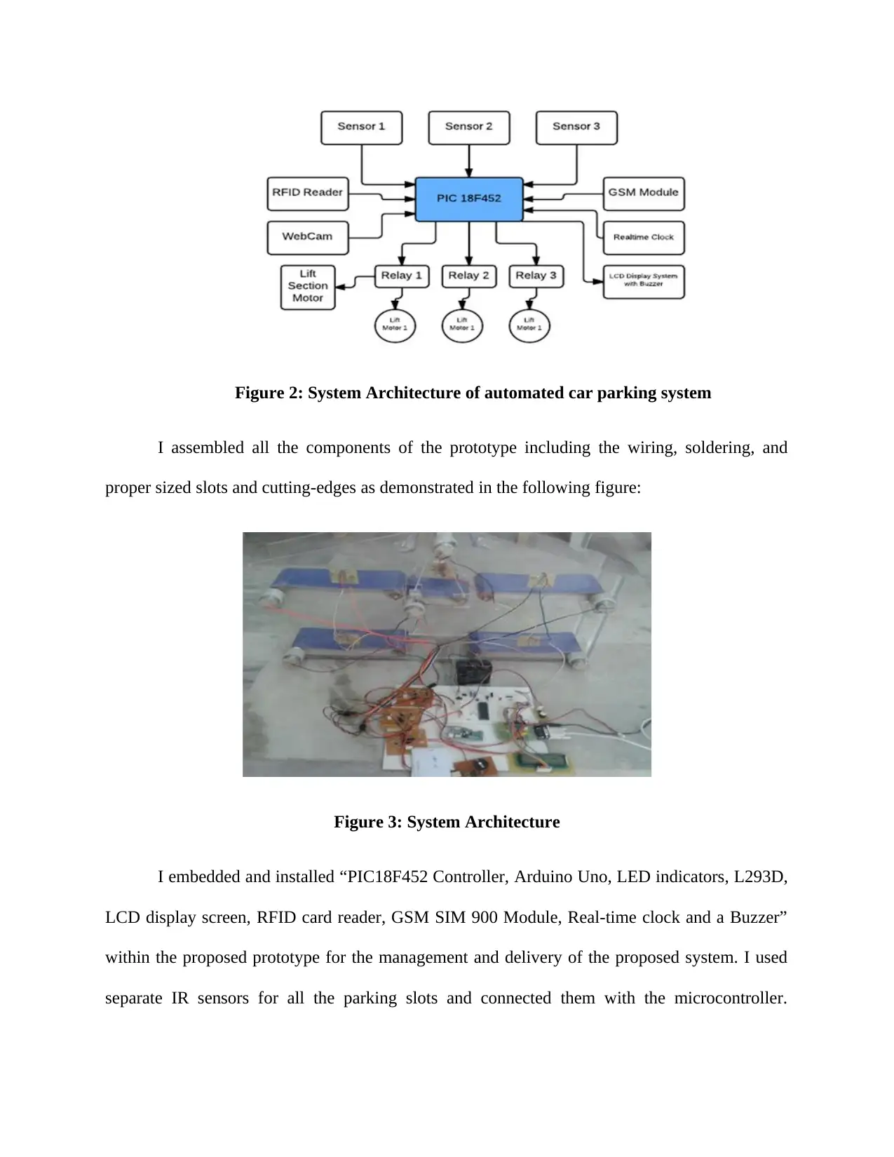
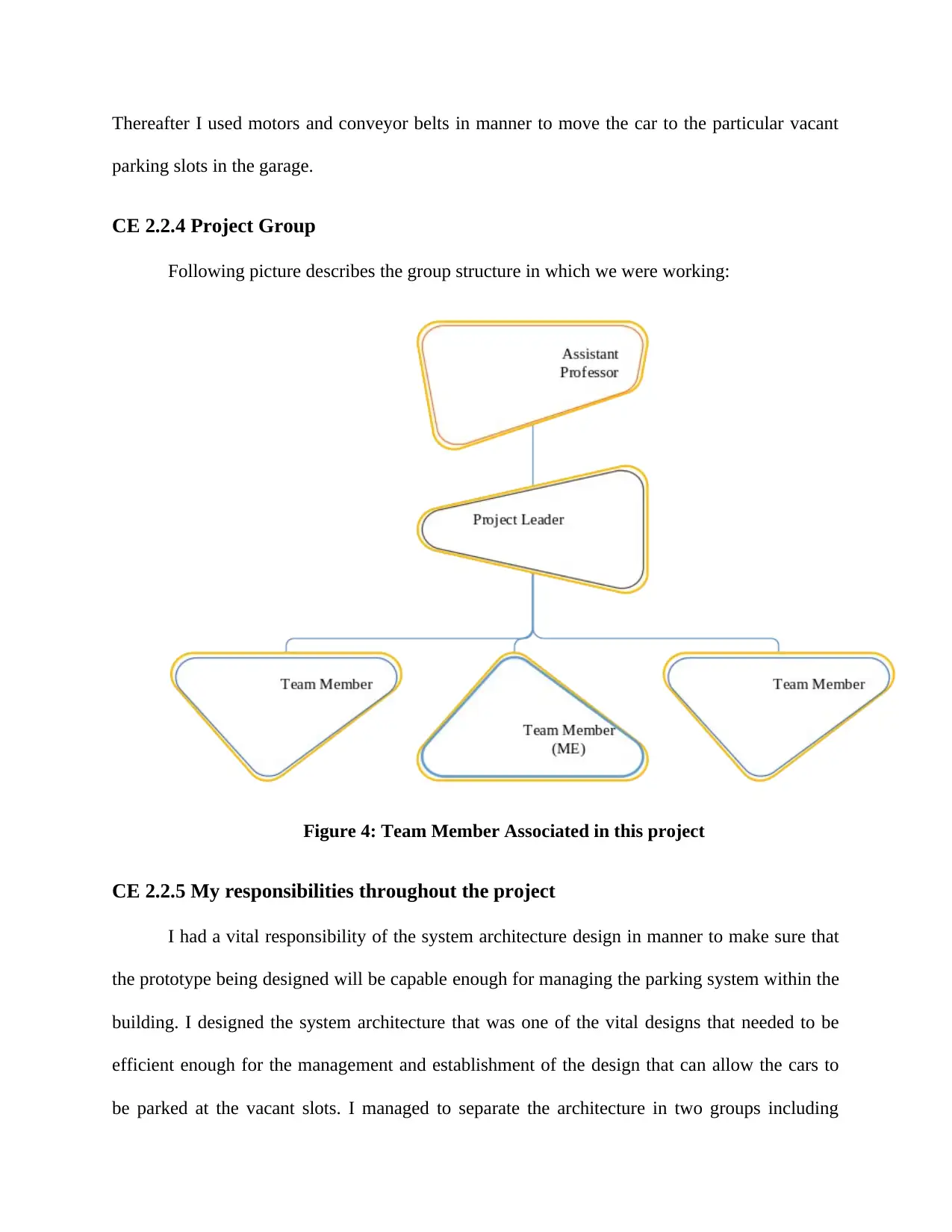
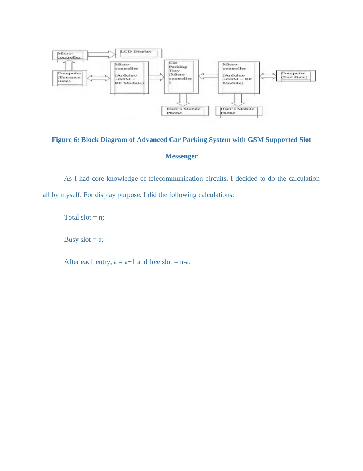
This competency demonstration report details the development of an advanced car parking system with GSM support, designed to address car parking challenges in developing and developed countries. The project involves creating a prototype model of a car parking tower with a central lift, PIC controller, and RFID reader to automate the parking process. The system utilizes Arduino IDE for coding, real-time clock calculation for charge determination, and includes components like IR sensors, motors, and conveyor belts for car movement. The author's role as a Telecommunication Engineer involved designing the system architecture, assembling components, and integrating GSM and RFID technology. The report covers the project's objectives, system design, engineering knowledge applied, accomplishments, and identified issues with their solutions, providing a comprehensive overview of the project's development and implementation.
Document Page
COMPETENCY
DEMONSTRATION REPORT
Career Episode 2
tabler-icon-diamond-filled.svg

Paraphrase This Document

Need a fresh take? Get an instant paraphrase of this document with our AI Paraphraser
Document Page
CE 2.1 Project Information
Name of the project: Developing Advanced Car Parking System with GSM Supported Slot
Messenger
Location of the project: [PLEASE FILL]
Project Duration: [PLEASE FILL]
University: [PLEASE FILL]
Role and Designation during the time: Telecommunication Engineer
CE 2.2 Project Background
CE 2.2.1 Characteristics of the project
Car parking has been always a considerable point of concern for the developing and
developed countries. I considered it as a world problem and designed a system that can allow
unique and smart car parking system that can be helpful in supporting the modern-day tedious
car parking with the help of the PIC controller and RFID reader. I proposed a prototype model
that can be helpful in implementing a car parking tower that has two floors and two slots per
floor around the either side of the central lift. A central lift has been installed in the prototype
where the users will be asked to mobilize their vehicles and the PIC controller will analyse the
vacant place and the slots and park the car in the corresponding slots. This prototype was consist
of software, motors, and conveyor belts in manner to transfer the car to the particular vacant
space. I have used Arduino IDE software for coding purpose. The real time clock calculator has
been also embedded in this prototype for the determination of the period for which the car was
Document Page
parked and thus, Ecommerce Company will be deducting respective charges. Therefore, I have
provided a compact design for an advanced car parking system.
CE 2.2.2 Objectives developed for the project
It is necessary for every project to have a concentric objective on which the individuals of
the team can focus in manner to accomplish the final delivery of the project. Following set of
objectives were followed for the delivery of this project:
To develop an automated and sophisticated model for car parking.
To utilize the RFID and PIC controller for the development of the parking system.
To minimize the problem with the car parking in a building and allowing the individuals
to have the exact space for their respective vehicles.
To use Arduino Ide software to complete the programming and coding of this project.
To compare and contrast the experimental results with my expected results in the project.
CE 2.2.3 My area of work
I was hired as the Telecommunication Engineer in this project. There were two sections
of the project and we had a group of four team members including guide and so, we divided the
project in two groups. I was assigned the responsibility to design the architecture of the prototype
with one of my fellow mates and other two were assigned to system design section. I developed
the following preliminary design of the prototype of the automatic car parking system:
Document Page
Figure 2: System Architecture of automated car parking system
I assembled all the components of the prototype including the wiring, soldering, and
proper sized slots and cutting-edges as demonstrated in the following figure:
Figure 3: System Architecture
I embedded and installed “PIC18F452 Controller, Arduino Uno, LED indicators, L293D,
LCD display screen, RFID card reader, GSM SIM 900 Module, Real-time clock and a Buzzer”
within the proposed prototype for the management and delivery of the proposed system. I used
separate IR sensors for all the parking slots and connected them with the microcontroller.
tabler-icon-diamond-filled.svg

Paraphrase This Document

Need a fresh take? Get an instant paraphrase of this document with our AI Paraphraser
Document Page
Thereafter I used motors and conveyor belts in manner to move the car to the particular vacant
parking slots in the garage.
CE 2.2.4 Project Group
Following picture describes the group structure in which we were working:
Figure 4: Team Member Associated in this project
CE 2.2.5 My responsibilities throughout the project
I had a vital responsibility of the system architecture design in manner to make sure that
the prototype being designed will be capable enough for managing the parking system within the
building. I designed the system architecture that was one of the vital designs that needed to be
efficient enough for the management and establishment of the design that can allow the cars to
be parked at the vacant slots. I managed to separate the architecture in two groups including
Document Page
parking tower and the assembled PIC and IC controller and rest of the electrical and electronic
components. After the instalment of all the devices the central lift needed to be shift to the
ground floor and thus, I used the conveyor belts and DC motors for the management of this
mechanic. Moreover, I have used Ardruino IDE software for capturing and storing the various
images of car registration number and driver. Being a telecommunication engineer, I was also
given responsibility to check the entire system architecture of this project that was developed by
one of my team members and while developing the prototype model, I paid extra attention to the
GSM module and RFID reader. I selected GSM SIM 900 module as it is a completed Quad-band
GPRS or GSM solution that could be embedded in several applications. Thereafter, I will
activate all the IR sensors in manner to process the data related to the vacant or filled parking
places.
CE 2.3 Distinctive Activity
CE 2.3.1 Comprehending the Theory of Project
The theory of the project was to design a building of two floors that can be further
extended as per the needs and requirements, that can allow the users to park their car in an
automated way. I embedded the central lift where the users will be asked to take their care in
manner to identify and allocate the car to the respective vacant slot. I embedded the IR sensors at
every slot that will be continuously recording and transmitting the data that whether the place is
vacant or not and assigning respective slots for the vehicles. The input will be sent to the RFID
reader and the microcontroller with process the further signal. The controller will activate the
motors and the conveyor belts for allowing the auto moving of the cars to the vacant place.
Document Page
I selected L293d motor driver as it enables voltage for applying across a load. There were
four switches (S1, S2, S3 and S4) of solid state and mechanical. When I closed the switches of
S1 and S4 and opened S3 and S2, positive voltage was applied across the load. Simultaneously,
when I opened S1 and S4 and closed S3 and S2, reverse voltage was applied.
S1 S2 S3 S4 Result
1 0 0 1 Motor moving right
0 1 1 0 Motor moving left
0 1 0 1 Motor brake
1 0 1 0 Motor brake
1 1 0 0 Short circuit
0 0 1 1 Short circuit
0 1 1 1 Short Circuit
1 1 1 1 Short circuit
Table 1: 4 Switch Operations of L293d Motor
Regarding LCD display screen, I selected power supply range of 4.7 V to 5 V. Due to the
presence of display arbitrary, I checked for low information content like present words, 7
segment displays or digits, which are similar to the digital clock. Regarding the software
components, I have used Arduino IDE software for compiling the program into microcontroller.
This software utilizes C programming language for the coding purpose. I have used function
tabler-icon-diamond-filled.svg

Paraphrase This Document

Need a fresh take? Get an instant paraphrase of this document with our AI Paraphraser
Document Page
from Arduino library for getting authentication of GPS data and SIM and sending or receiving
data through RF module.
CE 2.3.2 Engineering knowledge and skills applied in the project
I proposed a design that comprised of two floor buildings and two car parking slots at
each floor through the application of the moving conveyor, motors, IR sensors, RFID readers,
PIC controller and other electronic components. I also added a GSM add on module that will be
automatically responding the users SMS on whether there is vacant space available or not or
previously book the slot for further application. Following system design was developed for the
delivery of the proposed system:
Figure 3: System Design of automated car parking system
I tried to keep the system more informative for the user through introducing a LCD at the
entrance describing the vacant slots availability and the request made by the user for entering the
system. I captured the following outcome on the LCD screen as it was being recorded through
sending SMS:
Document Page
Figure 5: Demonstrating the process and functioning of entrance gate LCD screen
With my knowledge in digital circuits and network analysis, I proposed the design of this
advanced car parking system. I have even applied my knowledge of communication systems,
telecom networks and signals or systems to make the project supported by GSM. Moreover, for
the software part, I have used my understanding of Arduino IDE software.
CE 2.3.3 Accomplishment and Task Performed
I have made this project of Advanced Car Parking System with 3 major components of
Arduino Uno R3, RF module and GSM module. The main part of the system was
microcontroller within Arduino R3. I completed the coding part with Arduino IDE software and
decided to include the feature of operating updating slot information to LCD display at entrance
with the help of RF transmitter module.
Document Page
Figure 6: Block Diagram of Advanced Car Parking System with GSM Supported Slot
Messenger
As I had core knowledge of telecommunication circuits, I decided to do the calculation
all by myself. For display purpose, I did the following calculations:
Total slot = n;
Busy slot = a;
After each entry, a = a+1 and free slot = n-a.
tabler-icon-diamond-filled.svg

Paraphrase This Document

Need a fresh take? Get an instant paraphrase of this document with our AI Paraphraser
Document Page
Figure 7: Flowchart of Display
Regarding central command, I found out that initially the count was n, allocated slot was
0 and the number of slots was a. However, after each input, it became:
n = n+1 and the allocated slot = allocated slot +1.
Code = (3399 – (allocated slot x 7)) + (n – 1200) + (a x 3)).
Document Page
Figure 8: Flowchart of Central Command
Regarding car parking tray, initially count was n, allocated slot was 0 and the number of
slots was a. I checked the stop watch number is equal to allocated slots and the stop watch value
(n) = elapsed time. The price of slot (n) = stop watch value x price per unit.
The time to reach 1st slot from the entrance is equal to m and the distance A = n x m. the
time to reach end slot from the exit is equal to o and the distance B = o x n.
Distance 1 = n + distance A and Distance 2 = n + distance B.
chevron_up_icon
1 out of 16
circle_padding
hide_on_mobile
zoom_out_icon
[object Object]