A Research Paper on Advanced Construction Methods and Technology
VerifiedAdded on 2023/04/23
|15
|4058
|470
Report
AI Summary
This research paper provides a detailed overview of advanced construction methods and technologies used in civil engineering infrastructure projects. It covers various tunnel construction methods such as underwater tunneling, box jacking, bored tunneling, cut-and-cover, and shaft methods, highlighting the VSM technology for shaft installation. The report also discusses flexible and rigid roadway designs, emphasizing the materials and construction processes involved in each type. Furthermore, it explores construction methods for small concrete and earthfill dams, along with essential precautions. The paper aims to enhance understanding of modern construction techniques and improve efficiency and quality in civil engineering projects. Desklib offers a range of resources, including past papers and solved assignments, to support students in their studies.
Construction Methods 1
ADVANCED CONSTRUCTION METHODS AND TECHNOLOGY
A Research Paper on Construction Methods By
Student’s Name
Name of the Professor
Institutional Affiliation
City/State
Year/Month/Day
ADVANCED CONSTRUCTION METHODS AND TECHNOLOGY
A Research Paper on Construction Methods By
Student’s Name
Name of the Professor
Institutional Affiliation
City/State
Year/Month/Day
Paraphrase This Document
Need a fresh take? Get an instant paraphrase of this document with our AI Paraphraser
Construction Methods 2
Table of Contents
INTRODUCTION.......................................................................................................................................3
Tunnel Construction and Shafts...................................................................................................................3
Underwater Tunnel Method.....................................................................................................................3
Box Jacking Method................................................................................................................................4
Bored Tunnel Method..............................................................................................................................4
Cut-and-Cover Method............................................................................................................................5
Shaft Method...........................................................................................................................................6
Shaft Installation..........................................................................................................................................6
Flexible and Rigid Roadway.......................................................................................................................7
Flexible Roadway....................................................................................................................................7
Rigid Roadway........................................................................................................................................9
Small Concrete Dams................................................................................................................................10
Earthfill Dams.......................................................................................................................................11
Precautions................................................................................................................................................12
Rockfill Dam.............................................................................................................................................12
Precautions................................................................................................................................................13
CONCLUSION.........................................................................................................................................13
References.................................................................................................................................................14
Construction Methods 3
INTRODUCTION
In the civil engineering infrastructure work, the efficiency improvement and work quality
enhancement are determined by the application of new advanced technologies in the projects of
civil engineering. This research paper provides comprehensive details of the methods for
installation used for the construction of tunnel and shafts to ensure productive and safe operation,
details in the design of a rigid and flexible roadway, and also the construction methods of small
concrete dams as well as precautions that need to be considered.
Tunnel Construction and Shafts
The construction of the tunnel is a passage underground provided underneath water or earth
surface. Some of the installation methods used for the tunnel construction underwater tunnels,
box jacking method, pipe jacking method, shaft method, clay kicking method, bored tunnel
method, and cut and cover method (Berga, et al., 2003).
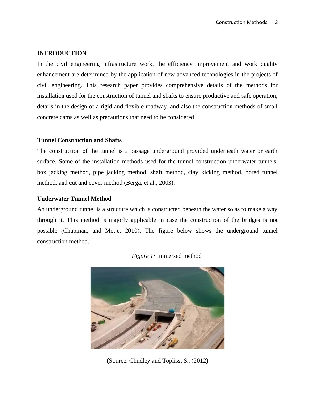
Underwater Tunnel Method
An underground tunnel is a structure which is constructed beneath the water so as to make a way
through it. This method is majorly applicable in case the construction of the bridges is not
possible (Chapman, and Metje, 2010). The figure below shows the underground tunnel
construction method.
Figure 1: Immersed method
(Source: Chudley and Topliss, S., (2012)
INTRODUCTION
In the civil engineering infrastructure work, the efficiency improvement and work quality
enhancement are determined by the application of new advanced technologies in the projects of
civil engineering. This research paper provides comprehensive details of the methods for
installation used for the construction of tunnel and shafts to ensure productive and safe operation,
details in the design of a rigid and flexible roadway, and also the construction methods of small
concrete dams as well as precautions that need to be considered.
Tunnel Construction and Shafts
The construction of the tunnel is a passage underground provided underneath water or earth
surface. Some of the installation methods used for the tunnel construction underwater tunnels,
box jacking method, pipe jacking method, shaft method, clay kicking method, bored tunnel
method, and cut and cover method (Berga, et al., 2003).
Underwater Tunnel Method
An underground tunnel is a structure which is constructed beneath the water so as to make a way
through it. This method is majorly applicable in case the construction of the bridges is not
possible (Chapman, and Metje, 2010). The figure below shows the underground tunnel
construction method.
Figure 1: Immersed method
(Source: Chudley and Topliss, S., (2012)
⊘ This is a preview!⊘
Do you want full access?
Subscribe today to unlock all pages.
Trusted by 1+ million students worldwide
Construction Methods 4
This method can also involve the use of very huge concrete-filled steel tunnel or pre-cast
concrete elements which are fabricated before the construction process, and then later installed
beneath the water surface. After the process of installation, the tunnels are backfilled. The
tunnels to be immersed can be improvised floodable shipways or basins or fabricated along the
length required in dry docks (Chudley, and Greeno, 2006).
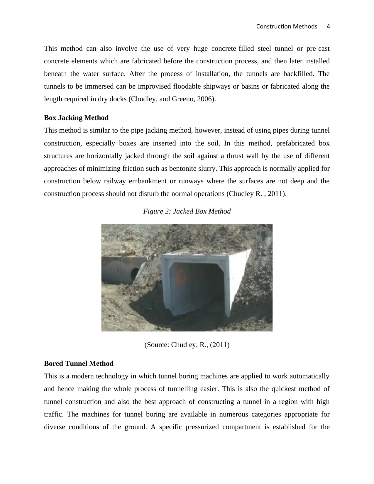
Box Jacking Method
This method is similar to the pipe jacking method, however, instead of using pipes during tunnel
construction, especially boxes are inserted into the soil. In this method, prefabricated box
structures are horizontally jacked through the soil against a thrust wall by the use of different
approaches of minimizing friction such as bentonite slurry. This approach is normally applied for
construction below railway embankment or runways where the surfaces are not deep and the
construction process should not disturb the normal operations (Chudley R. , 2011).
Figure 2: Jacked Box Method
(Source: Chudley, R., (2011)
Bored Tunnel Method
This is a modern technology in which tunnel boring machines are applied to work automatically
and hence making the whole process of tunnelling easier. This is also the quickest method of
tunnel construction and also the best approach of constructing a tunnel in a region with high
traffic. The machines for tunnel boring are available in numerous categories appropriate for
diverse conditions of the ground. A specific pressurized compartment is established for the
This method can also involve the use of very huge concrete-filled steel tunnel or pre-cast
concrete elements which are fabricated before the construction process, and then later installed
beneath the water surface. After the process of installation, the tunnels are backfilled. The
tunnels to be immersed can be improvised floodable shipways or basins or fabricated along the
length required in dry docks (Chudley, and Greeno, 2006).
Box Jacking Method
This method is similar to the pipe jacking method, however, instead of using pipes during tunnel
construction, especially boxes are inserted into the soil. In this method, prefabricated box
structures are horizontally jacked through the soil against a thrust wall by the use of different
approaches of minimizing friction such as bentonite slurry. This approach is normally applied for
construction below railway embankment or runways where the surfaces are not deep and the
construction process should not disturb the normal operations (Chudley R. , 2011).
Figure 2: Jacked Box Method
(Source: Chudley, R., (2011)
Bored Tunnel Method
This is a modern technology in which tunnel boring machines are applied to work automatically
and hence making the whole process of tunnelling easier. This is also the quickest method of
tunnel construction and also the best approach of constructing a tunnel in a region with high
traffic. The machines for tunnel boring are available in numerous categories appropriate for
diverse conditions of the ground. A specific pressurized compartment is established for the
Paraphrase This Document
Need a fresh take? Get an instant paraphrase of this document with our AI Paraphraser
Construction Methods 5
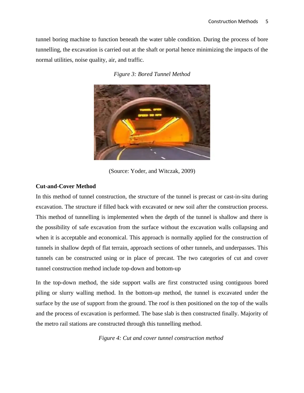
tunnel boring machine to function beneath the water table condition. During the process of bore
tunnelling, the excavation is carried out at the shaft or portal hence minimizing the impacts of the
normal utilities, noise quality, air, and traffic.
Figure 3: Bored Tunnel Method
(Source: Yoder, and Witczak, 2009)
Cut-and-Cover Method
In this method of tunnel construction, the structure of the tunnel is precast or cast-in-situ during
excavation. The structure if filled back with excavated or new soil after the construction process.
This method of tunnelling is implemented when the depth of the tunnel is shallow and there is
the possibility of safe excavation from the surface without the excavation walls collapsing and
when it is acceptable and economical. This approach is normally applied for the construction of
tunnels in shallow depth of flat terrain, approach sections of other tunnels, and underpasses. This
tunnels can be constructed using or in place of precast. The two categories of cut and cover
tunnel construction method include top-down and bottom-up
In the top-down method, the side support walls are first constructed using contiguous bored
piling or slurry walling method. In the bottom-up method, the tunnel is excavated under the
surface by the use of support from the ground. The roof is then positioned on the top of the walls
and the process of excavation is performed. The base slab is then constructed finally. Majority of
the metro rail stations are constructed through this tunnelling method.
Figure 4: Cut and cover tunnel construction method
tunnel boring machine to function beneath the water table condition. During the process of bore
tunnelling, the excavation is carried out at the shaft or portal hence minimizing the impacts of the
normal utilities, noise quality, air, and traffic.
Figure 3: Bored Tunnel Method
(Source: Yoder, and Witczak, 2009)
Cut-and-Cover Method
In this method of tunnel construction, the structure of the tunnel is precast or cast-in-situ during
excavation. The structure if filled back with excavated or new soil after the construction process.
This method of tunnelling is implemented when the depth of the tunnel is shallow and there is
the possibility of safe excavation from the surface without the excavation walls collapsing and
when it is acceptable and economical. This approach is normally applied for the construction of
tunnels in shallow depth of flat terrain, approach sections of other tunnels, and underpasses. This
tunnels can be constructed using or in place of precast. The two categories of cut and cover
tunnel construction method include top-down and bottom-up
In the top-down method, the side support walls are first constructed using contiguous bored
piling or slurry walling method. In the bottom-up method, the tunnel is excavated under the
surface by the use of support from the ground. The roof is then positioned on the top of the walls
and the process of excavation is performed. The base slab is then constructed finally. Majority of
the metro rail stations are constructed through this tunnelling method.
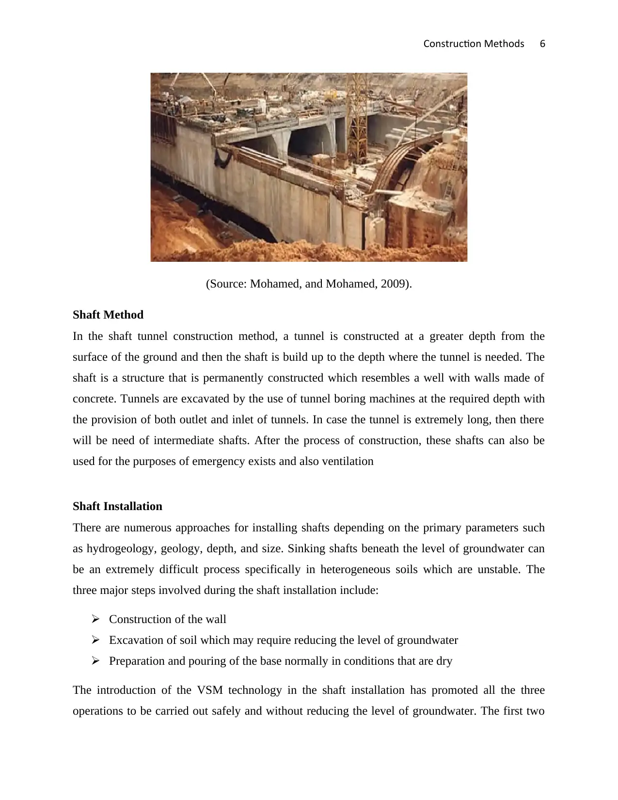
Figure 4: Cut and cover tunnel construction method
Construction Methods 6
(Source: Mohamed, and Mohamed, 2009).
Shaft Method
In the shaft tunnel construction method, a tunnel is constructed at a greater depth from the
surface of the ground and then the shaft is build up to the depth where the tunnel is needed. The
shaft is a structure that is permanently constructed which resembles a well with walls made of
concrete. Tunnels are excavated by the use of tunnel boring machines at the required depth with
the provision of both outlet and inlet of tunnels. In case the tunnel is extremely long, then there
will be need of intermediate shafts. After the process of construction, these shafts can also be
used for the purposes of emergency exists and also ventilation
Shaft Installation
There are numerous approaches for installing shafts depending on the primary parameters such
as hydrogeology, geology, depth, and size. Sinking shafts beneath the level of groundwater can
be an extremely difficult process specifically in heterogeneous soils which are unstable. The
three major steps involved during the shaft installation include:
Construction of the wall
Excavation of soil which may require reducing the level of groundwater
Preparation and pouring of the base normally in conditions that are dry
The introduction of the VSM technology in the shaft installation has promoted all the three
operations to be carried out safely and without reducing the level of groundwater. The first two
⊘ This is a preview!⊘
Do you want full access?
Subscribe today to unlock all pages.
Trusted by 1+ million students worldwide
Construction Methods 7
steps are carried out in parallel followed by pouring the base hence resulting in higher rates of
performance. The VSM technology is composed of three significant components, namely the
excavation unit which cuts the soil significantly with a strength of approximately 80MPa, a
slurry discharge system which removes the soil excavated and then transports the soil and water
mixture through a slurry line to a separation plant on the ground surface
There is also a centrifugal unit which removes the fine particles hence improving the transport of
the soil excavated and ensuring clean shaft water which can easily be disposed of. The last
component is the lowering unit which stabilizes the whole of the shaft construction process
against sinking that is uncontrolled through holding the entire weight of shaft through hydraulic
jacks and steel strands. All the functions of the machine are remotely controlled from the surface
by an operator without necessarily viewing the machine of shaft bottom
Flexible and Rigid Roadway
There are two types of the roadway based on the design consideration, namely, rigid roadway
and flexible roadway. The difference between rigid and flexible roadway is based on the
distribution of the loads on the subgrade.
Flexible Roadway
The flexible roadway is composed of a mixture of bituminous or asphaltic aggregates and a
material positioned on a bed compacted granular material of suitable quality layers over the
subgrade. This type of roadway denotes the deformation of subgrade as well as the subsequent
layers to the surface. The asphaltic aggregates are laid without any reinforcement or with specific
fabric reinforcement which permits restricted flow or repositioning of the roadbed under changes
in the ground. The flexible roadway design is based on the distribution of load characteristics of
the layers of components. The entire flexible roadway has negligible or low flexible strength in
their structural action. The flayers of flexible roadway transmit the compressive and vertical
stresses to the layers beneath through grain transfer by points of contact of granular structure
(Littlewood, 2012).
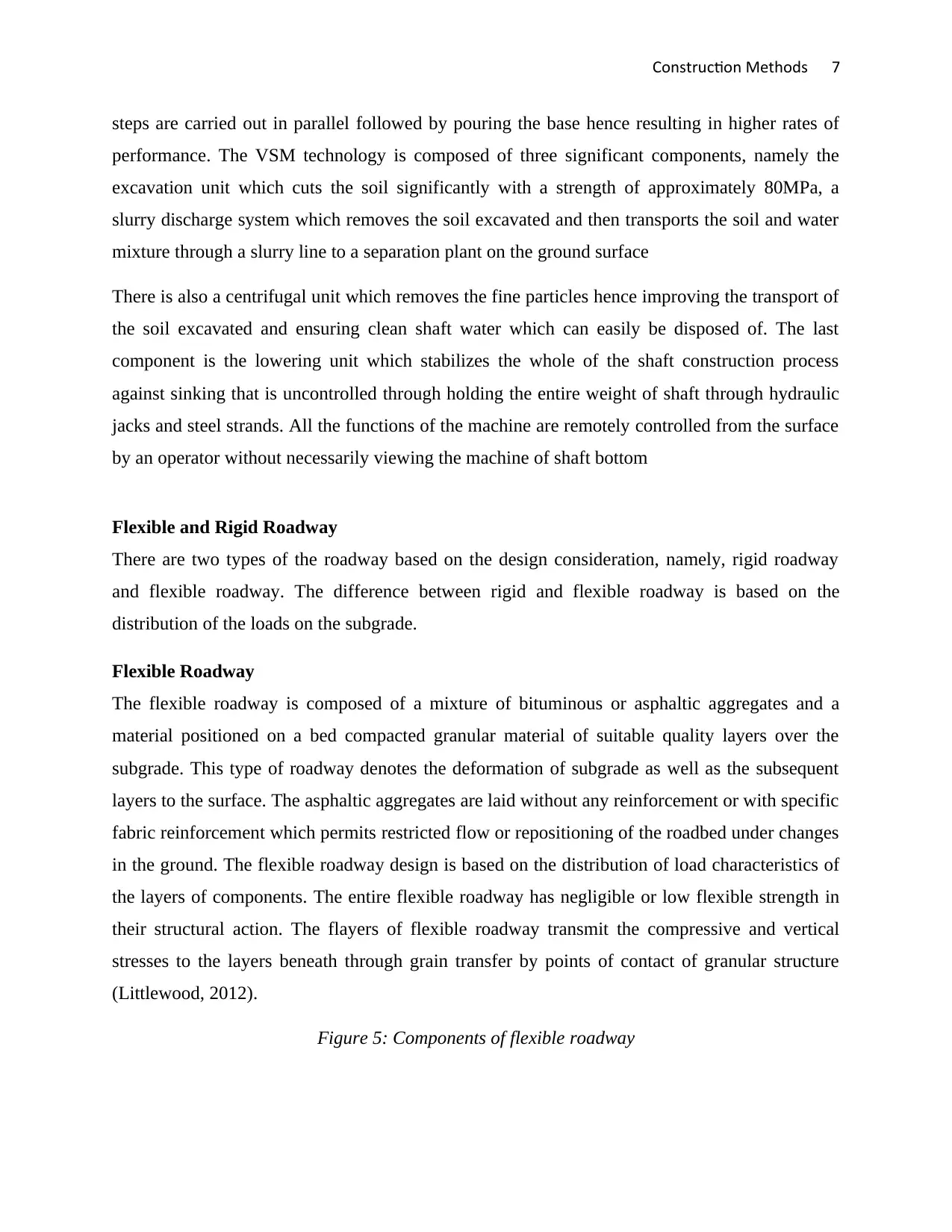
Figure 5: Components of flexible roadway
steps are carried out in parallel followed by pouring the base hence resulting in higher rates of
performance. The VSM technology is composed of three significant components, namely the
excavation unit which cuts the soil significantly with a strength of approximately 80MPa, a
slurry discharge system which removes the soil excavated and then transports the soil and water
mixture through a slurry line to a separation plant on the ground surface
There is also a centrifugal unit which removes the fine particles hence improving the transport of
the soil excavated and ensuring clean shaft water which can easily be disposed of. The last
component is the lowering unit which stabilizes the whole of the shaft construction process
against sinking that is uncontrolled through holding the entire weight of shaft through hydraulic
jacks and steel strands. All the functions of the machine are remotely controlled from the surface
by an operator without necessarily viewing the machine of shaft bottom
Flexible and Rigid Roadway
There are two types of the roadway based on the design consideration, namely, rigid roadway
and flexible roadway. The difference between rigid and flexible roadway is based on the
distribution of the loads on the subgrade.
Flexible Roadway
The flexible roadway is composed of a mixture of bituminous or asphaltic aggregates and a
material positioned on a bed compacted granular material of suitable quality layers over the
subgrade. This type of roadway denotes the deformation of subgrade as well as the subsequent
layers to the surface. The asphaltic aggregates are laid without any reinforcement or with specific
fabric reinforcement which permits restricted flow or repositioning of the roadbed under changes
in the ground. The flexible roadway design is based on the distribution of load characteristics of
the layers of components. The entire flexible roadway has negligible or low flexible strength in
their structural action. The flayers of flexible roadway transmit the compressive and vertical
stresses to the layers beneath through grain transfer by points of contact of granular structure
(Littlewood, 2012).
Figure 5: Components of flexible roadway
Paraphrase This Document
Need a fresh take? Get an instant paraphrase of this document with our AI Paraphraser
Construction Methods 8
(Source: Littlewood, 2012)
The stress due to vertical compression is maximum on the surface roadway directly below the
wheel load and is equivalent to the contact pressure beneath the wheels. The stresses decrease in
the lower layer because of the capability to distribute the stress to a huge area in the truncated
shape cone. As much the flexible roadway may be built in numerous layers, the top layer should
be strongest compared to the highest stresses caused by compression.
Construction of Subgrade: The materials used in the construction of the subgrade include an
aggregate of dimension 50mm, gravel, moorum, and selected soil. The subgrade is constructed
through spreading the loose soil and compacting the soil spread at a maximum moisture content
of the layer of soil. The optimum thickness after compaction of every layer is normally restricted
to 2000mm for each morth (Nadel, 2012).
Sub-base Course: The materials used in the construction of the sub-base course include selected
soil with low plasticity and less fine, coarse sand, gravel, and crushed stone aggregates. The sub-
base course can be constructed on the top of the subgrade prepared. The materials of sub-base
are spread to a specific cross slope and uniform thickness. Then the content of moisture of the
materials is determined and extra water quantity needed to increase the moisture content to the
optimum is sprinkled at the same rate. The loose layer of sub-base course can be compacted by
the use of a roller (Nikolaides, 2014).
Base Course: The materials used in the construction of the Base Course include Sufficient
proportion of water and hard crushed aggregates thoroughly mixed in the mixing plant. The Base
Course is basically mixed in the mixing plant and then the mixture is transported to the site and
spread by the use of paver finisher machines which is self-propelled. The layer of Base Course is
then compacted by the use of vibratory roller of the compacted thickness of less than 200 mm
Construction Methods 9
and low static weight of about 10 tonnes. The layer of Base Course is then dried for
approximately hours in dry weather (Overman, 2008).
Rigid Roadway
A rigid roadway can be constructed from the reinforced concrete slab or cement concrete. The
rigid roadway design is based on the provision of a structural slab of concrete cement of suitable
strength to resist the traffic loads. The rigid roadway has a high modulus of elasticity and rigidity
to distribute the load over a huge surface area of soil. Some of the reasons for the application of
rigid roadway in road construction include extreme weather conditions, poor drainage, poor soil
conditions, and very heavy rainfall (Perkins, 2010).
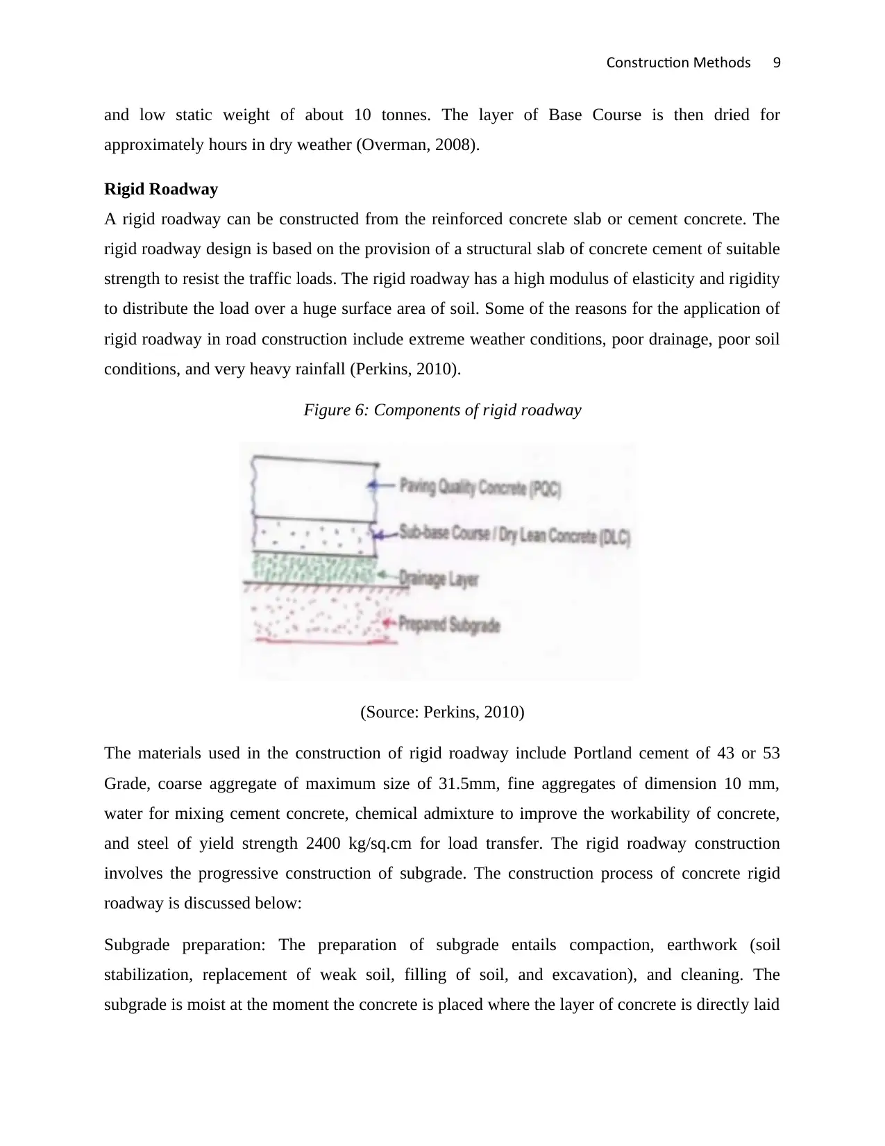
Figure 6: Components of rigid roadway
(Source: Perkins, 2010)
The materials used in the construction of rigid roadway include Portland cement of 43 or 53
Grade, coarse aggregate of maximum size of 31.5mm, fine aggregates of dimension 10 mm,
water for mixing cement concrete, chemical admixture to improve the workability of concrete,
and steel of yield strength 2400 kg/sq.cm for load transfer. The rigid roadway construction
involves the progressive construction of subgrade. The construction process of concrete rigid
roadway is discussed below:
Subgrade preparation: The preparation of subgrade entails compaction, earthwork (soil
stabilization, replacement of weak soil, filling of soil, and excavation), and cleaning. The
subgrade is moist at the moment the concrete is placed where the layer of concrete is directly laid
and low static weight of about 10 tonnes. The layer of Base Course is then dried for
approximately hours in dry weather (Overman, 2008).
Rigid Roadway
A rigid roadway can be constructed from the reinforced concrete slab or cement concrete. The
rigid roadway design is based on the provision of a structural slab of concrete cement of suitable
strength to resist the traffic loads. The rigid roadway has a high modulus of elasticity and rigidity
to distribute the load over a huge surface area of soil. Some of the reasons for the application of
rigid roadway in road construction include extreme weather conditions, poor drainage, poor soil
conditions, and very heavy rainfall (Perkins, 2010).
Figure 6: Components of rigid roadway
(Source: Perkins, 2010)
The materials used in the construction of rigid roadway include Portland cement of 43 or 53
Grade, coarse aggregate of maximum size of 31.5mm, fine aggregates of dimension 10 mm,
water for mixing cement concrete, chemical admixture to improve the workability of concrete,
and steel of yield strength 2400 kg/sq.cm for load transfer. The rigid roadway construction
involves the progressive construction of subgrade. The construction process of concrete rigid
roadway is discussed below:
Subgrade preparation: The preparation of subgrade entails compaction, earthwork (soil
stabilization, replacement of weak soil, filling of soil, and excavation), and cleaning. The
subgrade is moist at the moment the concrete is placed where the layer of concrete is directly laid
⊘ This is a preview!⊘
Do you want full access?
Subscribe today to unlock all pages.
Trusted by 1+ million students worldwide
Construction Methods 10
over the subgrade. There will be need of sprinkling water over the surface before concrete course
if laid in case the subgrade is dry, however, there is need of taking into consideration the water
pools and soft patches which may be formed at the surface.
Slip-form paver: This machine is a system that is self-propelled and can finish, compact, trim,
and spread automatically in a synchronized way by the use of its feedback sensors. This machine
is used is spraying of curing compounds, surface texturing, and the introduction of joint grooves
during the construction of the concrete rigid roadway.
Texturing: The finished concrete is expected to have a smooth surface and this can be done by
texturing of the surface of concrete so as to ensure that the surface has the required skid
resistance. Texturing can be performed through grooving or wire brushing along the transverse
direction.
Concrete curing: This process of curing is done to ensure maintenance of requisite temperature
and moisture content so that the resultant roadway attains strength through cement hydration.
This can be done by use of a high water retentive curing compound which is spread over the
roadway completed preventing faster drying of water.
Joints: Joints assist in releasing the stresses caused by the shrinkage of concrete, subgrade
moisture variation, and temperature variation. Some of the types of joints used in concrete rigid
roadway include the transverse joints namely the construction joints, expansion joints, and
contraction joints and also the longitudinal joints. The construction joints are designed so as to
transfer flexural stresses generated in the slab loads that are external and also to enable the
displacement between each slab section. The contraction joints prevent the formation of irregular
cracks caused by restraint in free concrete contraction (Nikolaides, 2014).
Joint filler: The spaces left by joints are filled with a compressible filler material which possess
properties such as durability, elasticity, and compressibility. Some of the types of joint fillers that
can be used include cork bound with bitumen, impregnated fibre, and softwood (Li, 2011).
Small Concrete Dams
Small concrete dams have numerous specific characteristics during their surveillance,
construction, design, and preliminary studies. The major distinctive feature of a small concrete
Paraphrase This Document
Need a fresh take? Get an instant paraphrase of this document with our AI Paraphraser
Construction Methods 11
dam is its technical aspect such as the technique of drilling small vertical drain after the process
of construction is completed.
Earthfill Dams
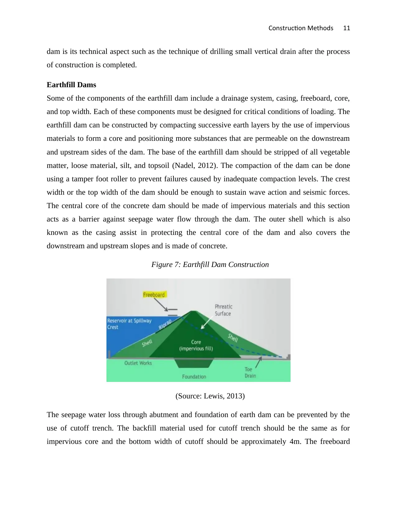
Some of the components of the earthfill dam include a drainage system, casing, freeboard, core,
and top width. Each of these components must be designed for critical conditions of loading. The
earthfill dam can be constructed by compacting successive earth layers by the use of impervious
materials to form a core and positioning more substances that are permeable on the downstream
and upstream sides of the dam. The base of the earthfill dam should be stripped of all vegetable
matter, loose material, silt, and topsoil (Nadel, 2012). The compaction of the dam can be done
using a tamper foot roller to prevent failures caused by inadequate compaction levels. The crest
width or the top width of the dam should be enough to sustain wave action and seismic forces.
The central core of the concrete dam should be made of impervious materials and this section
acts as a barrier against seepage water flow through the dam. The outer shell which is also
known as the casing assist in protecting the central core of the dam and also covers the
downstream and upstream slopes and is made of concrete.
Figure 7: Earthfill Dam Construction
(Source: Lewis, 2013)
The seepage water loss through abutment and foundation of earth dam can be prevented by the
use of cutoff trench. The backfill material used for cutoff trench should be the same as for
impervious core and the bottom width of cutoff should be approximately 4m. The freeboard
dam is its technical aspect such as the technique of drilling small vertical drain after the process
of construction is completed.
Earthfill Dams
Some of the components of the earthfill dam include a drainage system, casing, freeboard, core,
and top width. Each of these components must be designed for critical conditions of loading. The
earthfill dam can be constructed by compacting successive earth layers by the use of impervious
materials to form a core and positioning more substances that are permeable on the downstream
and upstream sides of the dam. The base of the earthfill dam should be stripped of all vegetable
matter, loose material, silt, and topsoil (Nadel, 2012). The compaction of the dam can be done
using a tamper foot roller to prevent failures caused by inadequate compaction levels. The crest
width or the top width of the dam should be enough to sustain wave action and seismic forces.
The central core of the concrete dam should be made of impervious materials and this section
acts as a barrier against seepage water flow through the dam. The outer shell which is also
known as the casing assist in protecting the central core of the dam and also covers the
downstream and upstream slopes and is made of concrete.
Figure 7: Earthfill Dam Construction
(Source: Lewis, 2013)
The seepage water loss through abutment and foundation of earth dam can be prevented by the
use of cutoff trench. The backfill material used for cutoff trench should be the same as for
impervious core and the bottom width of cutoff should be approximately 4m. The freeboard
Construction Methods 12
which is the vertical distance from the top of the dam to the spillway level should be a minimum
of 0.05m with additional 0.25m to take into considerations the potential actions of the wave.
Precautions
It is important for the earthfill dam to be constructed during a few months of the dry season so as
to prevent floods and heavy rains. There is also need of coming up with cross sections and
solutions to solve the problems of internal erosion, imperviousness, and mechanical stability.
The lowest compaction effort should be 95% Standards MDD. In case the compaction effort
range varies in the entire dam, then it may result in the dam settling to different degrees hence
leading to cracking. The concrete materials used in the construction should be placed with
enough moisture to ensure suitable compaction. The range of moisture content should be
between -1% and 3% (Littlewood, 2012).
Rockfill Dam
A rockfill dam is a dam made of compacted granular soil combines with impervious regions of
the dam. The structure contains an impervious zone which is normally selected aggregates with
filler zones and an area resistant to rainwater. Filters are used in the prevention of soil migration
hence resulting in reduced internal erosion. Filters are majorly graded soil that is designed to
prevent the migration of particles of fine grain. The major components of the rockfill dam
include the auxiliary supporting members, impervious zone, and the main rockfill (Perkins,
2010).
The construction of the rockfill dam begins by placing the material in controlled lifts. The
compactors used in the construction are the steel drum roller so as to ensure that the materials are
locked into place to minimize settlement during the following years. These rollers are also
applied to prevent segregation of materials caused by fall lift rock on the slopes. The height of
the dam can then be increased by adding extra rocks beneath the diaphragm without
encroachment of the research region. The major rockfill provides the support for its own stability
as well as weight, whereas the membrane supporting the water produces an impervious zone.
⊘ This is a preview!⊘
Do you want full access?
Subscribe today to unlock all pages.
Trusted by 1+ million students worldwide
1 out of 15


Your All-in-One AI-Powered Toolkit for Academic Success.
+13062052269
info@desklib.com
Available 24*7 on WhatsApp / Email
![[object Object]](/_next/static/media/star-bottom.7253800d.svg)
Unlock your academic potential
Copyright © 2020–2026 A2Z Services. All Rights Reserved. Developed and managed by ZUCOL.