Analysis of PMSM Performance with Field Oriented Control (42091)
VerifiedAdded on 2022/09/16
|12
|1670
|26
Homework Assignment
AI Summary
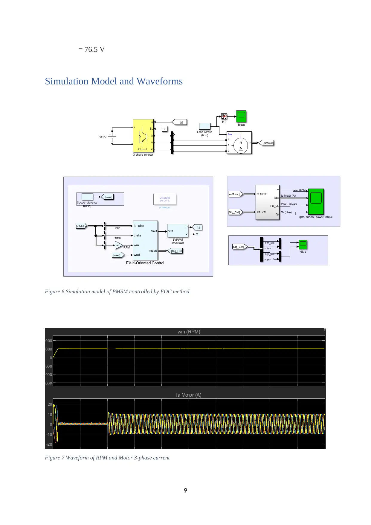
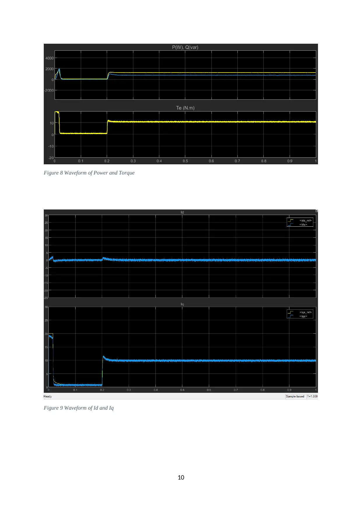
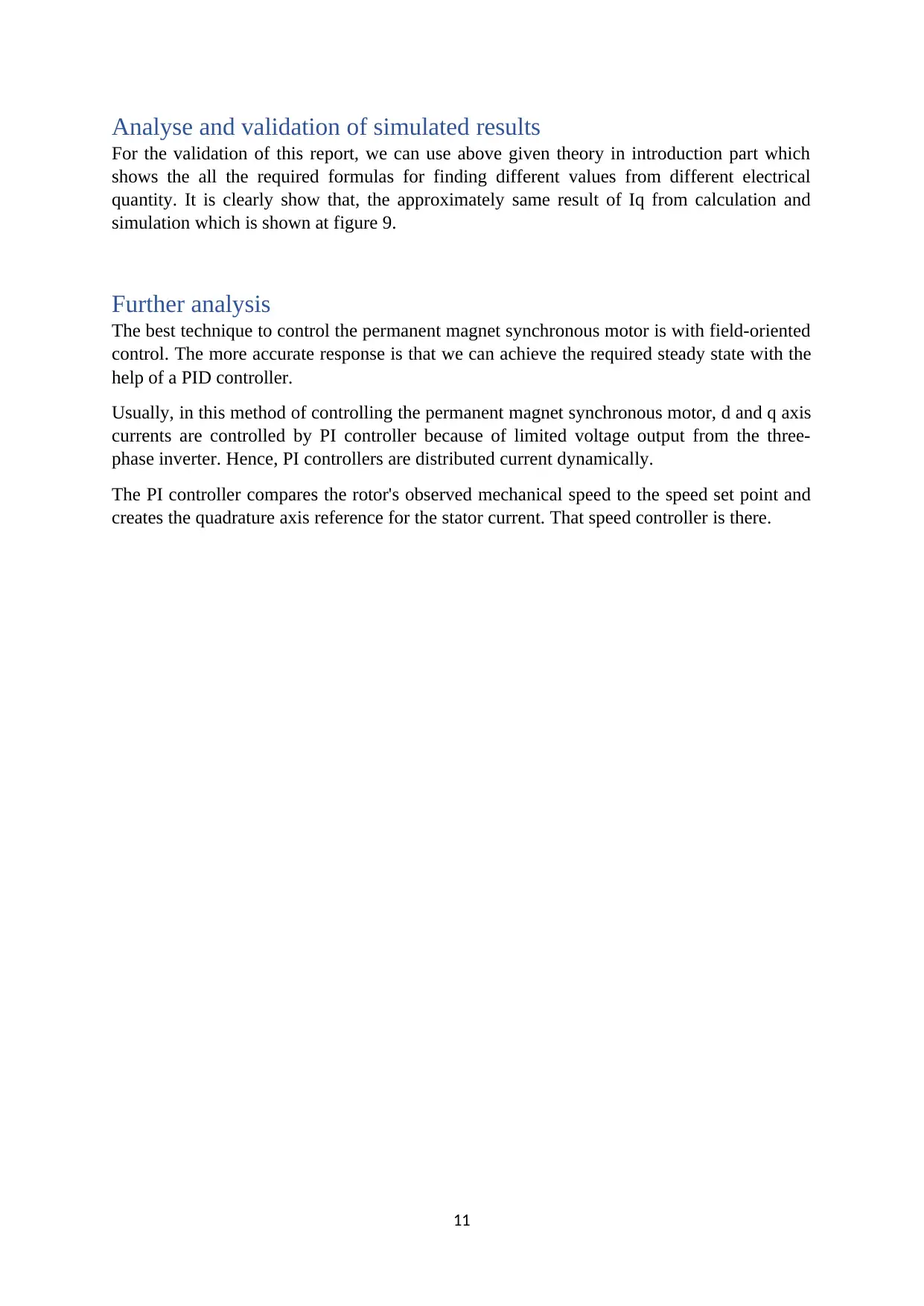
This assignment explores the control of a Permanent Magnet Synchronous Motor (PMSM) using Field Oriented Control (FOC). The report begins with an introduction to PMSMs, highlighting their advantages, applications, and construction, including surface-mounted and interior permanent magnet configurations. It then delves into the working principle and mathematical modeling of PMSMs, including equivalent circuits and dq reference frame analysis. The core of the assignment focuses on FOC, detailing its block diagram, forward Clarke and reverse Park transformations, and the role of PI controllers. Steady-state performance calculations, including iq and EMF, are presented. The report includes a simulation model and waveforms demonstrating the motor's performance, followed by an analysis and validation of the simulated results. The report concludes with a discussion of further analysis and relevant references.

Advanced Energy Conversion Systems (42091)
Assignment: 1 (part 2)
Submitted to:
Submitted from
1
Assignment: 1 (part 2)
Submitted to:
Submitted from
1
Paraphrase This Document
Need a fresh take? Get an instant paraphrase of this document with our AI Paraphraser

Contents
Introduction...........................................................................................................................................3
Construction......................................................................................................................................3
PMSM working principle and Mathematical modelling....................................................................4
Field Oriented Control (FOC) block diagram....................................................................................6
Calculation of some steady-state performance......................................................................................9
Simulation Model and Waveforms........................................................................................................9
Analyse and validation of simulated results.........................................................................................12
Further analysis...................................................................................................................................12
References...........................................................................................................................................13
Table of figures
Figure 1 (a) Surface mounted magnets (b) Inside placed magnet..........................................................4
Figure 2 Equivalent circuit of PMSM....................................................................................................5
Figure 3 Reference frame......................................................................................................................5
Figure 4 Field Oriented Control.............................................................................................................7
Figure 5 waveforms and axis.................................................................................................................8
Figure 6 Simulation model of PMSM controlled by FOC method......................................................10
Figure 7 Waveform of RPM and Motor 3-phase current.....................................................................10
Figure 8 Waveform of Power and Torque...........................................................................................11
Figure 9 Waveform of Id and Iq..........................................................................................................11
2

Introduction
A permanent magnet synchronous motor (PMSM) is like between Induction motor and
brushless DC motor. When compared to conventional motors, the permanent magnet
synchronous motor's operation is incredibly simple, quick torque response with better
dynamic operation, and efficient.
Hence, PMSM is became one of the best choices for a wide range of motion control
applications. PMSM used in actuators, robotics, machine tools, traction applications and
electric vehicles. Usually, high-performance operation is possible with surface-mounted
magnets are fixed to a rotor, resulting in the minimal possible of armature effect with a wide
air gap.
Advantages and applications of PMSM:
Highly efficient and reliable
Construction and maintenance are easier than Induction motor
Smooth torque and maintaining full torque at low speed
Used in Air conditioners, refrigerators, electrical power steering of vehicles, data storage units and
many more.
Construction
The only structural difference between the permanent magnet synchronous motor and the
conventional synchronous motor is the rotor. Permanent magnets are used to create field
poles because the rotor without any field winding while conventional synchronous motor
requires rotor winding. Samarium-cobalt and medium, iron, and boron are employed to make
the permanent magnets used in the PMSM.
Magnets can be placed on the rotor's surface for operations at medium speeds or internal for
activities at high speeds, as shown in figure 1.
Figure 1 (a) Surface mounted magnets (b) Inside placed magnet
3
⊘ This is a preview!⊘
Do you want full access?
Subscribe today to unlock all pages.

Trusted by 1+ million students worldwide

Surface-mounted PMSM
Figure 1(a) shows the permanent magnets placed on the surface of the outer periphery of
rotor. The disadvantage of this arrangement type is that it has less structural integrity and
mechanical resilience while providing the maximum air gap flux density. Surface - mounted
PMSMs are devices with this specific magnet structure.
Interior permanent magnet
The permanent magnets can also be embedded inside the rotor laminations, which is another
way to place them in the rotor. Generally known as Interior PMSM, this type of machine
structure is represented in figure 1(b). This arrangement's development was more complex
than that of permanent magnet rotors with a surface mount or an inserted magnet.
PMSM working principle and Mathematical modelling
The characteristic of synchronous motor is that run at uniform speed even if load is change.
In the permanent synchronous motor, a rotor produced constant magnetic field by permanent
magnets and stator generate revolving magnetic field at synchronous speed when emf applied
on winding terminals.
The rotating magnetic field (RMF) and constant magnetic field are attracted to each other and
they magnetically locked. Hence, rotor rotates at RMF speed.
Figure 2 Equivalent circuit of PMSM
4
Paraphrase This Document
Need a fresh take? Get an instant paraphrase of this document with our AI Paraphraser

The given figure 2 illustrates that the equivalent circuit
of PMSM without damper winding. For the
Mathematical model of the PMSM, we assume motor
operates at ideal condition.
considering, t- time
θr- angle between rotor d-axis
and stator axis
Three phase supply voltage can be written as:
Where, VA, VB and VC are the phase voltage; IA, IB and IC are the phase current; ψA, ψB and ψC
are flux linkage of rotor; Ls is phase inductance.
The rotor flux linkage written as given below equation 4, 5 and 6.
Using the dq reference frame, Voltage equation in dq form:
Where flux linkage
Substitution equation 9 and 10 in equation 7 and 8.
The developed torque by the motor Te:
For PMSM motor Ld = Lq = Ls at that time the torque generated by the PMSM:
5
Figure 3 Reference frame

Field Oriented Control (FOC) block diagram
Field Oriented Control used for achieving quick operations such as acceleration and
deacceleration and High-performance motor control. Now, using this technique, we can
control the PMSM drive like a separately excited DC motor.
In this method, motor controlled by three phase current and current on a space vector diagram
and it has magnitude and angle. At the 0° torque will be zero however, +90° and -90° we can
ger the maximum torque.
Figure 4 Field Oriented Control
When stator current MMF vector perpendicular to each other:
By measuring the rotor angle itself, it is simple to determine the rotor flux angle
in a permanent magnet motor. Because the angle of the rotor flux does not vary
while the rotor angle changes, this motor is known as a synchronous motor. The
rotor flux of an AC induction motor, however, is difficult because it slips in
across the rotor phase at the slip frequency. This rotor angle is measured by a
resolver or encoder.
6
⊘ This is a preview!⊘
Do you want full access?
Subscribe today to unlock all pages.

Trusted by 1+ million students worldwide

Forward Clarke Transformation
The Forward Clarke Transformation is a conversion of the three-phase vector value of current
into two orthogonal vector with same equivalent current. So only needed to change only two
current value rather than three current
For simplify above complex equation, consider the rotating reference frame Id and Iq
Then,
Where, d-axis is an
axis which is directly line up with rotor flux angle while quadrature axis with respect to the d-
axis is a q-axis.
Reverse Park Transformation
The reverse park transformation is convert the rotating voltage vectors (𝑉𝑑 and 𝑉𝑞) with
respect to stationary reference system (𝑉𝛼 and 𝑉𝛽).
………………….…………(a)
And,
……(b)
By putting value of equation(a) into equation(b),
7
Paraphrase This Document
Need a fresh take? Get an instant paraphrase of this document with our AI Paraphraser

Figure 5 waveforms and axis
PI Controllers
In this FOC approach, three PI controllers are deployed, of which two are used as inner loop
controllers and one as an outer loop controller. Inner loop controllers are used to control the
current Id and Iq, whereas outer loop controllers are used to control the motor's speed.
Calculation of some steady-state performance
(1) Calculation of iq
Given data: The number of poles: 4
Stator resistance R: 0.958
Flux linkage=0.1827
Rated speed=1000 rpm
Torque =10Nm
Torque=3/2*P*(Ψd*iq – Ψq*id) …………(a)
Now, we consider surface mounted PMSM, the value of id = 0
Hence,
Torque=3/2P(Ψd*iq)
10=1.5*4(0.1827* iq) ………….(b)
After solving equation (b),
iq = 9.18 A
(2) Maximum back EMF
Emf =Ke* ωmech …………………………(c)
Where Ke is the constant
ωmech =mechanical speed of motor into electrical quantity
ω=2πf
f = ω/2π
=np/60
ωr = 2πn/60
after putting all given value in equation (c),
emf = 2*3.14*1000*4*0.1827/60
8

= 76.5 V
Simulation Model and Waveforms
Figure 6 Simulation model of PMSM controlled by FOC method
Figure 7 Waveform of RPM and Motor 3-phase current
9
Simulation Model and Waveforms
Figure 6 Simulation model of PMSM controlled by FOC method
Figure 7 Waveform of RPM and Motor 3-phase current
9
⊘ This is a preview!⊘
Do you want full access?
Subscribe today to unlock all pages.

Trusted by 1+ million students worldwide

Figure 8 Waveform of Power and Torque
Figure 9 Waveform of Id and Iq
10
Figure 9 Waveform of Id and Iq
10
Paraphrase This Document
Need a fresh take? Get an instant paraphrase of this document with our AI Paraphraser

Analyse and validation of simulated results
For the validation of this report, we can use above given theory in introduction part which
shows the all the required formulas for finding different values from different electrical
quantity. It is clearly show that, the approximately same result of Iq from calculation and
simulation which is shown at figure 9.
Further analysis
The best technique to control the permanent magnet synchronous motor is with field-oriented
control. The more accurate response is that we can achieve the required steady state with the
help of a PID controller.
Usually, in this method of controlling the permanent magnet synchronous motor, d and q axis
currents are controlled by PI controller because of limited voltage output from the three-
phase inverter. Hence, PI controllers are distributed current dynamically.
The PI controller compares the rotor's observed mechanical speed to the speed set point and
creates the quadrature axis reference for the stator current. That speed controller is there.
11

References
[1] https://www.journalimcms.org/wp-content/uploads/68-Speed-Control-of-Permanent-RS-
29.pdf
[2] https://www.elprocus.com/what-is-a-permanent-magnet-synchronous-motor-its-working/
#:~:text=The%20working%20of%20PMSM%20depends,similar%20to%20brushless%20DC
%20motors.
[3] Permanent-Magnet Synchronous Machine Drives | IntechOpen
[4] MATLAB/SIMULINK MODEL OF FIELD ORIENTED CONTROL OF PMSM DRIVE USING SPACE
VECTORS by Remitha K Madhu and Anna Mathew Department of EE Engineering, Rajagiri
Institute of Science and Technology, Kochi, India Assistant Professor, Rajagiri Institute of
Science and Technology, Kochi, India
[5] THE FIELD ORIENTED CONTROL OF A PERMANENT MAGNET SYNCHROUNOUS MOTOR
(PMSM) BY USING FUZZY LOGIC by SAMAT BIN IDERUS a project report submitted in partial
fulfillment of the requirement for the award of the Degree of Master of Electrical
Engineering
12
⊘ This is a preview!⊘
Do you want full access?
Subscribe today to unlock all pages.

Trusted by 1+ million students worldwide
1 out of 12
Related Documents

Your All-in-One AI-Powered Toolkit for Academic Success.
+13062052269
info@desklib.com
Available 24*7 on WhatsApp / Email
Unlock your academic potential
Copyright © 2020–2025 A2Z Services. All Rights Reserved. Developed and managed by ZUCOL.