Advanced Flow Modelling: CFD Analysis of Rocket Nozzle at UTS

Verified

Added on  2023/04/20

|15
|2091
|308
Report
AI Summary
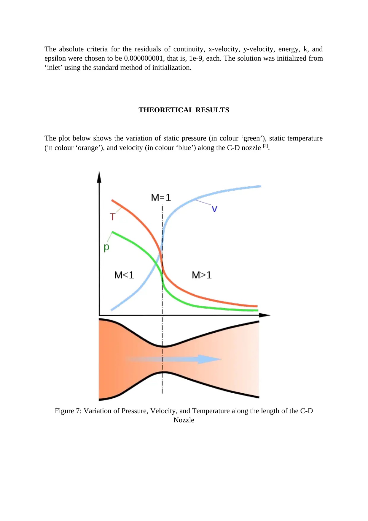
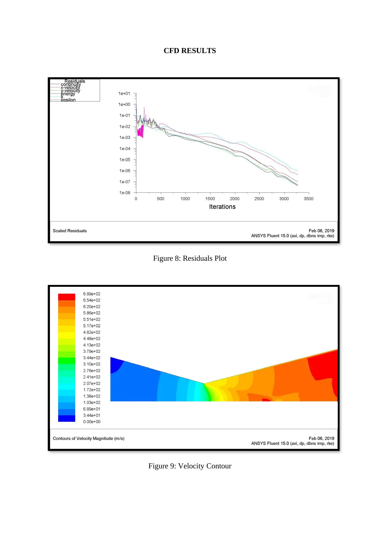
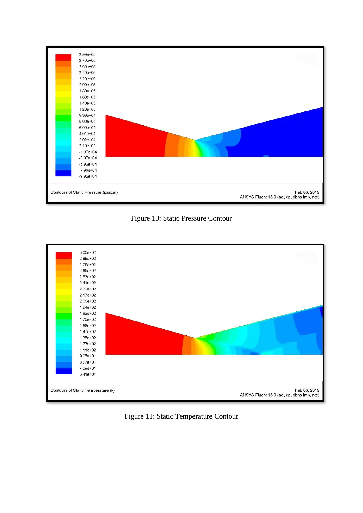
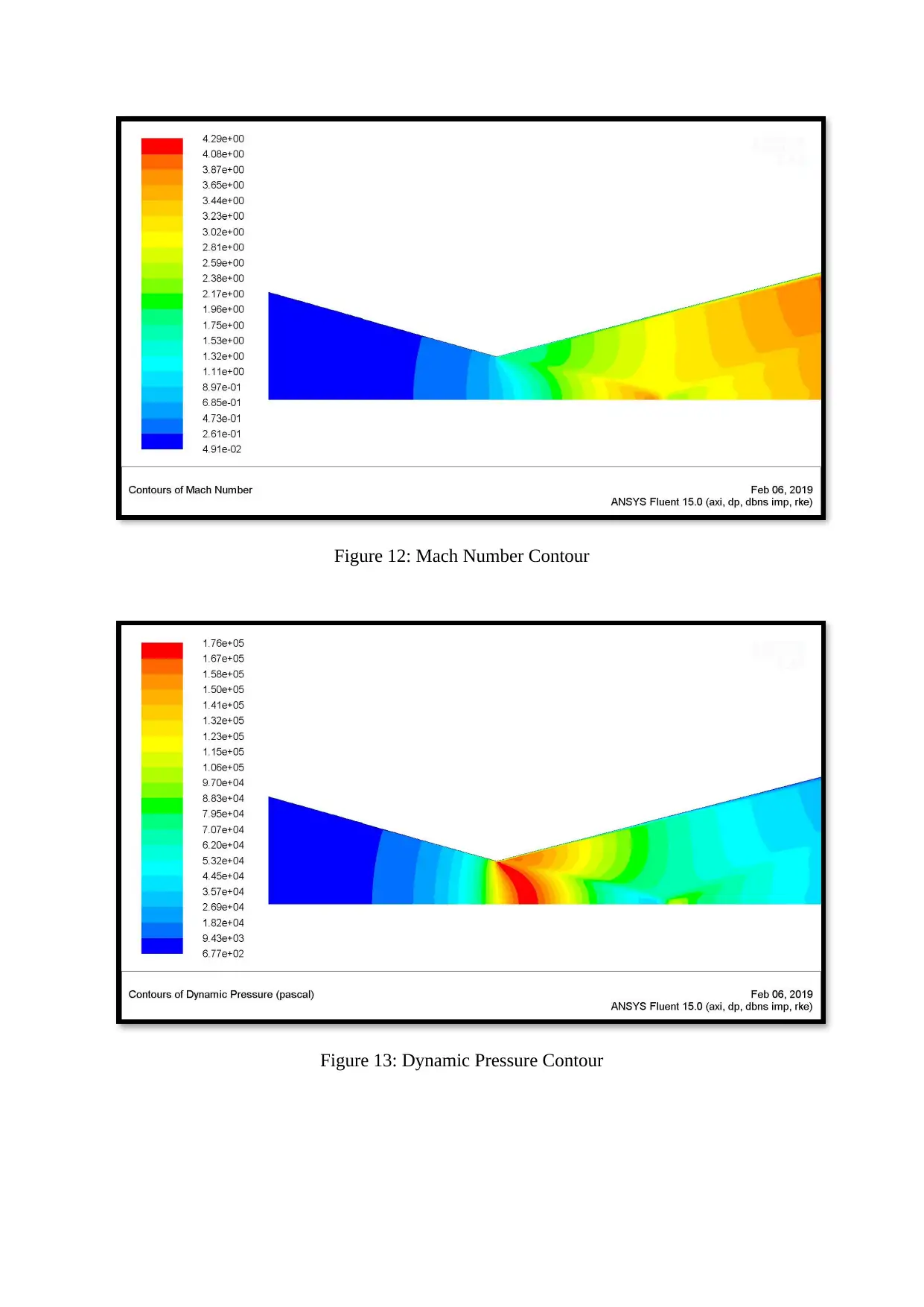
This report presents a Computational Fluid Dynamics (CFD) analysis of a rocket nozzle, specifically a convergent-divergent (de Laval) nozzle. The study begins with an introduction to rocket engine components and the function of the nozzle in converting thermal energy into kinetic energy. It outlines the key formulas governing nozzle design, including the area-velocity relationship and equations for sonic throat area, gas density, temperature, pressure, and mass flow rate. The nozzle geometry was modeled using CATIA V-5, followed by meshing in ANSYS ICEM CFD, ensuring high mesh quality, particularly near the throat and walls. The CFD analysis was performed using ANSYS Fluent, employing a density-based solver with specific settings for viscous models, gas properties, and boundary conditions. Theoretical results are compared with CFD results, demonstrating the variation of static pressure, temperature, and velocity along the nozzle length, with a focus on pressure drop near the throat and flow acceleration in the diverging section. The report concludes that the CFD results closely align with theoretical expectations, validating the simulation approach. The plots for residuals, velocity, static pressure, temperature, mach number, dynamic pressure and wall shear stress are presented and discussed.
Document Page
ADVANCED FLOW MODELLING INDIVIDIAL ASSIGNMENT
Topic: CFD Analysis of Rocket Nozzle
Roland Man Pan Ng 12071282
University of Technology Sydney
tabler-icon-diamond-filled.svg

Paraphrase This Document

Need a fresh take? Get an instant paraphrase of this document with our AI Paraphraser
Document Page
INTRODUCTION
A typical rocket engine consists of injectors – which delivers oxidizer and fuel to the
combustion chamber, a combustion chamber – where the fuel and oxidizer are mixed and
burned, and the nozzle – which converts the chemical and thermal energy of the gases into
the kinetic energy.
Most of the rocket nozzles are de Laval type or convergent-divergent type. They expand and
accelerate the gases coming from the combustion chamber to supersonic speeds. The de
Laval nozzle is divided into three sections – a converging section, throat, and a diverging
section.
The converging section section is where the the nozzle area reduces (dA is nagative) along
the direction of the flow of working fluid. The diverging section is where the nozzle area
increases (dA is positive) along the direction of the flow of working fluid. The throat is where
the cross-sectional area of the nozzle is at its minimum.
The operation of the rocket nozzle depends on the properties of the gas entering the nozzle.
Since the mass flow rate is constant, if the speed of the gas entering the nozzle is subsonic,
that is, Mach number lesser than 1, then the flow will accelerate downstream of the
converging section. As the gas reaches the throat, it attains sonic velocity, that is, Mach equal
to 1. Beyond the throat, the gases start to expand and further accelerate to supersonic speeds.
If the pressure of the exhaust gases is lesser than the ambient pressure, the nozzle is said to be
under-expanded, and when the pressure of the exhaust gases is greater than the abient
pressure, the nozzle is said to be over-expanded. In either case, the performance of the nozzle
or the efficiency of the nozzle is reduced. In order to obtain the maximum thrust and
maximum efficiency from the nozzle, the length of the nozzle is kept long enough so that the
pressure of the exhaust gases is almost equal to the ambient pressure.
Document Page
FORMULAE
The following expressions are considered while designing a de Laval nozzle.
Area-velocity relationship:
dA
A = (M2 – 1) du
u
Where,
u is the velocity at any station of the nozzle
A is the cross-sectional area of the nozzle
M is the Mach number
For Mach < 1 (subsonic flow), increase in velocity (positive du) is associated with a decrease
in area (negative dA). The equation now reduces to
dA
A = (M2 – 1) du
u ~ - du
u
For Mach > 1 (supersonic flow), increase in velocity (positive du) is associated with an
increase in area (positive dA). The equation now reduces to
dA
A = (M2 – 1) du
u ~ + du
u
At sonic condition, that is, Mach = 0, the equation reduces to
dA
A = (M2 – 1) du
u = (0) du
u
Sonic throat area, A*:
A
A¿ = 1
M [ 2
γ (1+ γ 1
2 M 2) ] γ +1
2(γ 1 )
Where,
A is the local area of the cross-section
A* is the throat area at Mach = 1
γ is the value which depends on the state of the gas. For air, γ = 1.4
At given A(x):
The quantities at the hypothetical sonic throat are denoted by a superscript ‘*’
The properties at the stagnation state are denoted by subscript ‘o’
Document Page
For the density of the gas, ρ
ρ1
ρ0
= [ 1+ γ 1
2 M2
] 1
(γ 1)
At M = 1 and γ = 1.4
ρ¿
ρ = [ 1+ γ 1
2 ] 1
(γ 1 ) = 0.6339
For the temperature, T
T1
T0
= [1+ γ 1
2 M 2
]1
At M = 1 and γ = 1.4
a¿
a0
= [ T¿
T o ] 1
2
= [1+ γ 1
2 ]1
2 = 0.9129
For the pressure, p
p1
p0
= [1+ γ 1
2 M2
] γ
γ 1
At M = 1 and γ = 1.4
p¿
p0
= [1+ γ 1
2 ] γ
γ1 = 0.5283
Mass flow rate, :
ṁ = γ po
( γ 1 ) ho {[1+ γ 1
2 M e
2¿ ] γ +1
2(γ 1)
} Me Ae
Where,
ho is the enthalpy
Me is the Mach number at the exit of the nozzle
Ae is the cross-sectional area at the exit of the nozzle
tabler-icon-diamond-filled.svg

Paraphrase This Document

Need a fresh take? Get an instant paraphrase of this document with our AI Paraphraser
Document Page
GEOMETRY OF THE CD-NOZZLE
The geometry [1] of the convergent-divergent nozzle was modelled using CATIA-V5.
(all dimensions are in mm)
The following are the 3-dimensional views of the modelled nozzle.
Figure 1: 3D model of the C-D Nozzle
Document Page
Figure 2: Isometric view of the 3D model of the C-D Nozzle
The CFD (Computational Fluid Dynamics) analysis can be done on this 3D model. That
would require building 3D mesh and then solving the problem using ANSYS Fluent or
ANSYS CFX. The whole process would need more computational time. But, the geometry of
the C-D nozzle is axisymmetric. So, if the symmetrical portion (which will be two-
dimensional) of the 3D model is considered, and the CFD analysis is performed on this
symmetrical part, that will fetch the same results and thereby saving the computational time.
The symmetrical portion:
Figure 3: The symmetrical portion of the C-D Nozzle
Document Page
MESHING OF THE CD-NOZZLE
The model was then imported to ANSYS ICEM CFD software, where the meshing was
created. A careful approach was taken to obtain a high-quality mesh. All the elements were
‘quadrilateral’ shaped. To obtain better results, a comparatively denser mesh was created near
the throat of the nozzle. A high resolution mesh was also created near the walls of the C-D
nozzle to capture the boundary layer phenomenon.
Figure 4: Mesh of the C-D Nozzle
Figure 5: Mesh near the walls of the C-D Nozzle
The solver (ANSYS Fluent) requires a minimum mesh quality of 0.6. In this case, the
minimum quality of the mesh is 0.99, which is much higher than the requirement.
tabler-icon-diamond-filled.svg

Paraphrase This Document

Need a fresh take? Get an instant paraphrase of this document with our AI Paraphraser
Document Page
The y-axis of the following plot shows the number of elements and the x-axis represents the
element quality.
Figure 6: Mesh quality of the C-D Nozzle
Table 1: Mesh Information
Number of quads 26334
Number of nodes 26700
Minimum quality 0.99
Minimum aspect ratio 1.01
Maximum aspect ratio 63.90
Minimum element skewness 0.957
CFD ANALYSIS OF THE CD-NOZZLE USING ANSYS FLUENT
After the meshing was complete, the mesh was converted into the unstructured mesh,
thereafter which the unstructured mesh was imported into ANSYS Fluent to solve the
problem.
Throughout the analysis, the flow through the convergent-divergent nozzle is assumed to be
isentropic.
The problem is a 2D case and was solved using double precession. The ‘density-based’ solver
was chosen for this problem, as the compressibility effects are dominant. In the solver
options, ‘axisymmetric’ formulation option is turned on, as the geometry is axisymmetric.
The ‘k-epsilon realizable (2 equation)’ viscous model with near wall-function as ‘scalable
wall functions’ was used to solve the problem. The density of the gas was chosen as ‘ideal
gas’, which has a constant specific heat of 1006.43 J/kg-K and thermal conductivity of
0.0242. The boundary conditions at the inlet of the nozzle were given as ‘pressure inlet’
having gauge total pressure of 300,000 Pa and the outlet was given as ‘pressure outlet’ having
gauge pressure of 0 Pa.
The solution method of the implicit type of formulation with Roe-FDS was chosen. The
special discretization of flow, turbulent kinetic energy, and turbulent dissipation rate was
given as ‘second order upwind’.
Document Page
The absolute criteria for the residuals of continuity, x-velocity, y-velocity, energy, k, and
epsilon were chosen to be 0.000000001, that is, 1e-9, each. The solution was initialized from
‘inlet’ using the standard method of initialization.
THEORETICAL RESULTS
The plot below shows the variation of static pressure (in colour ‘green’), static temperature
(in colour ‘orange’), and velocity (in colour ‘blue’) along the C-D nozzle [2].
Figure 7: Variation of Pressure, Velocity, and Temperature along the length of the C-D
Nozzle
Document Page
CFD RESULTS
Figure 8: Residuals Plot
Figure 9: Velocity Contour
tabler-icon-diamond-filled.svg

Paraphrase This Document

Need a fresh take? Get an instant paraphrase of this document with our AI Paraphraser
Document Page
Figure 10: Static Pressure Contour
Figure 11: Static Temperature Contour
Document Page
Figure 12: Mach Number Contour
Figure 13: Dynamic Pressure Contour
chevron_up_icon
1 out of 15
circle_padding
hide_on_mobile
zoom_out_icon
[object Object]