Advanced Networks Design Report: Traffic Management Center Project
VerifiedAdded on 2020/04/21
|18
|3504
|91
Report
AI Summary
This report details the design and implementation of an advanced network solution for a traffic management center. The report begins with a logical design diagram and IP addressing scheme, including IPv4 subnetting and a discussion on transitioning from IPv4 to IPv6. It then provides a comprehensive design report that covers the model description, business requirements, and protocols used, such as video compression codecs, PTZ cameras, UDP/RTP, HSRP, and spanning tree. The report also addresses security considerations. The network is designed to support remote access to video feeds, motion detection, high-resolution video, ANPR cameras, and secure video storage. The report utilizes a hierarchical design model with core, distribution, and access layers, and includes detailed subnet designs and VLAN configurations for cameras, storage servers, and media servers. Microsoft Visio is used for the network design, and the report provides insights into the integration of various network components like switches, firewalls, and servers. The report concludes with a discussion on the business requirements and protocols used in the implementation.

Running head: ADVANCED NETWORKS
Advanced Networks
Name of the Student
Name of the University
Author’s Note
Advanced Networks
Name of the Student
Name of the University
Author’s Note
Paraphrase This Document
Need a fresh take? Get an instant paraphrase of this document with our AI Paraphraser
1
ADVANCED NETWORKS
Table of Contents
PART 1 – Design.................................................................................................................3
Logical Design Diagram..................................................................................................3
IP Decision.......................................................................................................................3
IPv4 Subnetting...............................................................................................................5
Transition mechanism from Ipv4 to Ipv6 Subnet Designs..............................................5
Part 2 – Design Report.........................................................................................................7
1. Introduction..................................................................................................................7
2. Description of the model.............................................................................................7
3. Design..........................................................................................................................8
4. Business Requirement.................................................................................................9
5. Protocols....................................................................................................................10
5.1. Video compression Codecs.................................................................................10
5.2. Pan-Tilt-Zoom (PTZ)..........................................................................................11
5.3. UDP/RTP............................................................................................................11
5.4. HSRP..................................................................................................................12
5.5. Gateway Load balancing....................................................................................12
5.6. Spanning Tree.....................................................................................................12
5.7. PortFast Bridge protocol data Unit.....................................................................13
6. Security......................................................................................................................13
2
ADVANCED NETWORKS
Conclusion.....................................................................................................................14
Bibliography......................................................................................................................15
ADVANCED NETWORKS
Conclusion.....................................................................................................................14
Bibliography......................................................................................................................15
⊘ This is a preview!⊘
Do you want full access?
Subscribe today to unlock all pages.
Trusted by 1+ million students worldwide
3
ADVANCED NETWORKS
PART 1 – Design
Logical Design Diagram
IP Decision
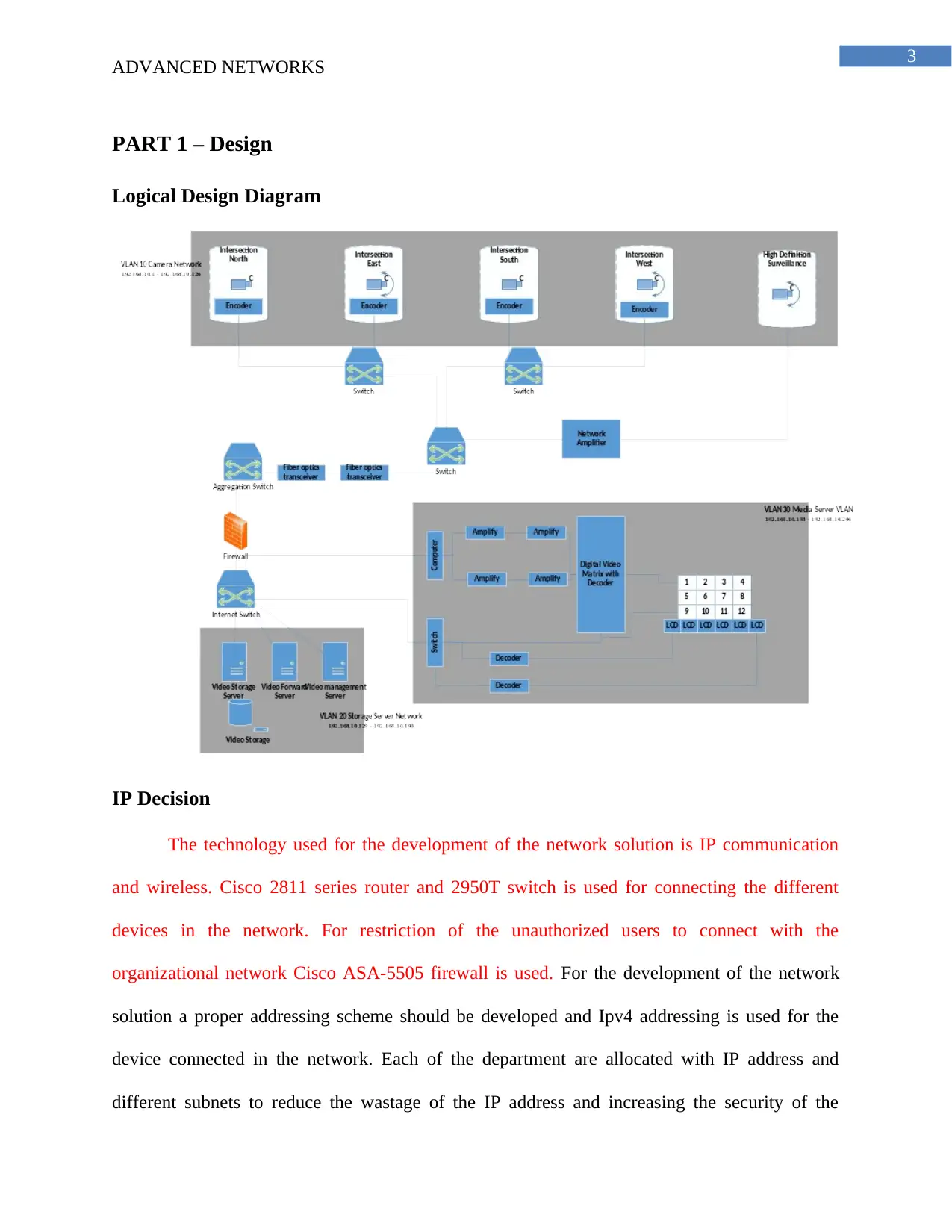
The technology used for the development of the network solution is IP communication
and wireless. Cisco 2811 series router and 2950T switch is used for connecting the different
devices in the network. For restriction of the unauthorized users to connect with the
organizational network Cisco ASA-5505 firewall is used. For the development of the network
solution a proper addressing scheme should be developed and Ipv4 addressing is used for the
device connected in the network. Each of the department are allocated with IP address and
different subnets to reduce the wastage of the IP address and increasing the security of the
ADVANCED NETWORKS
PART 1 – Design
Logical Design Diagram
IP Decision
The technology used for the development of the network solution is IP communication
and wireless. Cisco 2811 series router and 2950T switch is used for connecting the different
devices in the network. For restriction of the unauthorized users to connect with the
organizational network Cisco ASA-5505 firewall is used. For the development of the network
solution a proper addressing scheme should be developed and Ipv4 addressing is used for the
device connected in the network. Each of the department are allocated with IP address and
different subnets to reduce the wastage of the IP address and increasing the security of the
Paraphrase This Document
Need a fresh take? Get an instant paraphrase of this document with our AI Paraphraser
4
ADVANCED NETWORKS
network. The server network is sub netted and configured with access control list from denying
access of the unauthorized users to connect with the server.
The configuration of the network with IPv4 address would reduce the complexity of the
network and help the network administrator to monitor the activity of the users connected in the
network. Two IP address are required for the transportation of the video feeds in the network and
they are termed as source IP address and destination IP address1. The source and the destination
Ip address are subnetted for breaking the network into different parts such as host and network. If
100 cameras are required to be installed in the network then the cameras are required to be
provided with an IP address and all of them should be on the same subnet for increasing the
efficiency of the network2. Public or private address can be used for the network and it depends
upon the requirement of the organization3. If the direct access of the cameras are required to be
blocked in the internet then private IP address is used for the configuration.
Ipv4 addressing scheme is selected over the Ipv6 address because it is easy to remember
and it requires less programming or less memory for its operation. It have the option of future up
gradation and the network can be configured with dual stack network for allowing the network
device configured with IPv6 address to communicate with the device.
1 Seungchul Park, "A Rogue AP Detection Method Based On DHCP Snooping" (2016) 17(3) Journal of
Internet Computing and Services.
2 Ahiaba Solomon, A. A. and ThankGod Sani, "A Performance Study Of IPV6 Multicast Routing Over A
Dual Stack Virtual Local Area Network" (2016) 147(10) International Journal of Computer Applications.
3 Mahmood ul-Hassan et al, "Analysis Of Ipv4 Vs Ipv6 Traffic In US" (2016) 7(12) International Journal of
Advanced Computer Science and Applications.
5
ADVANCED NETWORKS
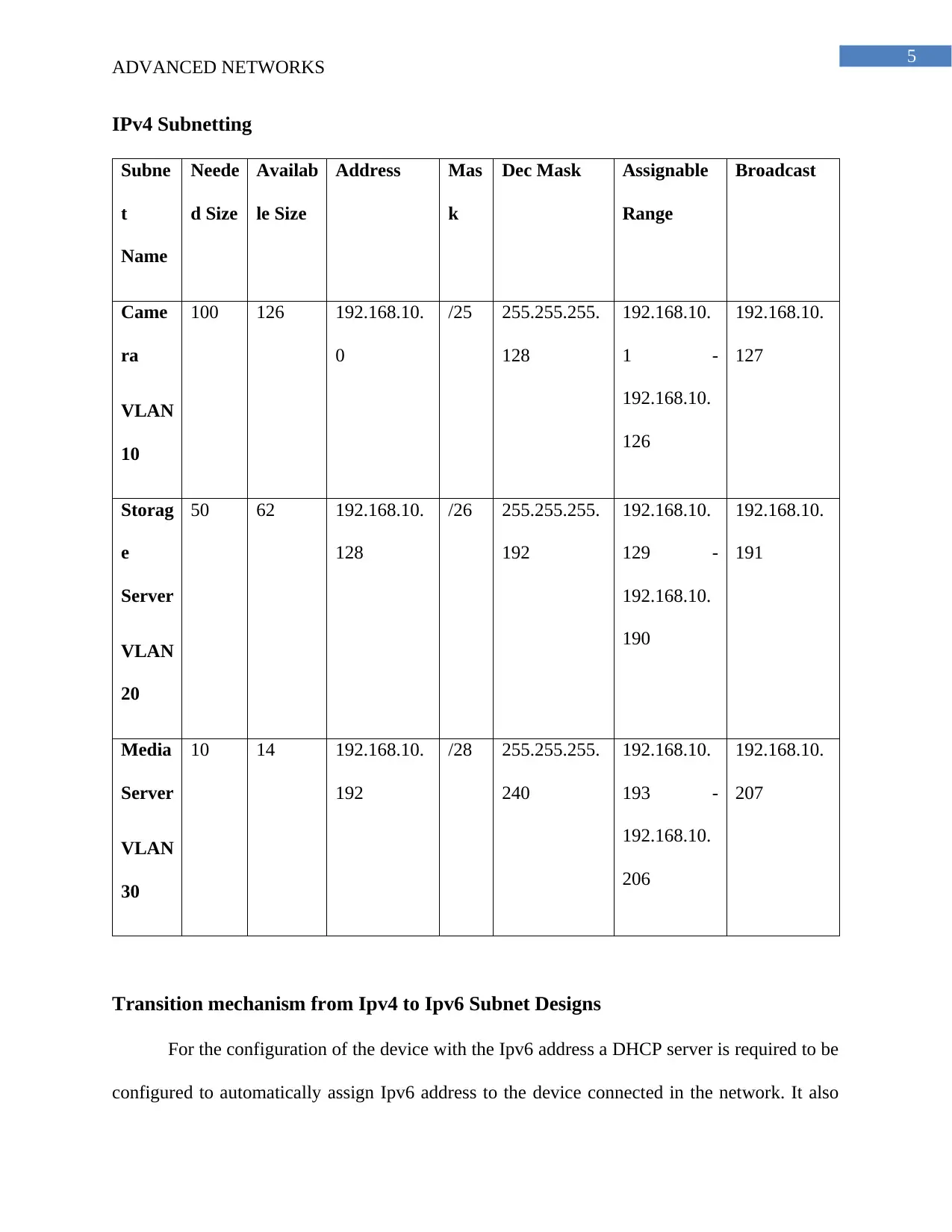
IPv4 Subnetting
Subne
t
Name
Neede
d Size
Availab
le Size
Address Mas
k
Dec Mask Assignable
Range
Broadcast
Came
ra
VLAN
10
100 126 192.168.10.
0
/25 255.255.255.
128
192.168.10.
1 -
192.168.10.
126
192.168.10.
127
Storag
e
Server
VLAN
20
50 62 192.168.10.
128
/26 255.255.255.
192
192.168.10.
129 -
192.168.10.
190
192.168.10.
191
Media
Server
VLAN
30
10 14 192.168.10.
192
/28 255.255.255.
240
192.168.10.
193 -
192.168.10.
206
192.168.10.
207
Transition mechanism from Ipv4 to Ipv6 Subnet Designs
For the configuration of the device with the Ipv6 address a DHCP server is required to be
configured to automatically assign Ipv6 address to the device connected in the network. It also
ADVANCED NETWORKS
IPv4 Subnetting
Subne
t
Name
Neede
d Size
Availab
le Size
Address Mas
k
Dec Mask Assignable
Range
Broadcast
Came
ra
VLAN
10
100 126 192.168.10.
0
/25 255.255.255.
128
192.168.10.
1 -
192.168.10.
126
192.168.10.
127
Storag
e
Server
VLAN
20
50 62 192.168.10.
128
/26 255.255.255.
192
192.168.10.
129 -
192.168.10.
190
192.168.10.
191
Media
Server
VLAN
30
10 14 192.168.10.
192
/28 255.255.255.
240
192.168.10.
193 -
192.168.10.
206
192.168.10.
207
Transition mechanism from Ipv4 to Ipv6 Subnet Designs
For the configuration of the device with the Ipv6 address a DHCP server is required to be
configured to automatically assign Ipv6 address to the device connected in the network. It also
⊘ This is a preview!⊘
Do you want full access?
Subscribe today to unlock all pages.
Trusted by 1+ million students worldwide
6
ADVANCED NETWORKS
increases the security of the network because the device configured with IPV6 address can be
tracked from remote location. The dual stack configuration of the network the devices are
configured with IPv4 and Ipv6 address and Ipv4 address is used for communicating with the
network configured with Ipv4 address and Ipv6 address is used for communicating with the
device configured with Ipv6 addressing scheme4.
Designing Subnets and VLANs
The subnet is designed for the allocation of the IP address to the device connected in the
network and for the network solution the cameras are kept in a different subnet of
192.168.10.0/25. The Storage servers are kept in the subnet of 192.168.10.128/25 and the Media
servers are allocated with the subnet 192.168.10.192/28.
Different VLANs are created for the connection of the different device and reduce the
congestion in the network. The creation of the VLAN improves the management of the network
components connected in the network and it becomes for the network administrator to monitor
the network from a single point. Each of the VLAN are named and connected using different
subnets for meeting the business requirement of the organization. The cameras are connected in a
VLAN and the servers and the other storage devices are kept in separate VLAN for increasing
the security of the network.
4 F. Barreto, "Ipv6 Protocol With Dual-Stack Technique In A Small Campus Network" (2015) 30(1)
Journal of Communication and Information Systems.
Paraphrase This Document
Need a fresh take? Get an instant paraphrase of this document with our AI Paraphraser
7
ADVANCED NETWORKS
Part 2 – Design Report
1. Introduction
The report is designed for the installation of Traffic management center by Amy
Networks and include the remote links for inclusion of the new features like automatic number
plate recognition. A preliminary design is created for the development of the network design and
a logical design is created for the inclusion of the control room and cellular network for
connecting the different device in then network. A proper IP addressing plan is created for the
allocation of the IP address to the device connected in the network. Different technology is used
for the development of the network such as installation of sensors and traffic sensing
technologies at different location.
2. Description of the model
Multi dimension model is used for the development of the network solution and the main
objective of the model is to simulate the traffic flow and predict the real time traffic for
streaming live videos via the media server5. Data collection scheme are used and different
routing algorithm are used for the management of the network traffic and storing the media in the
storage server of the network. A hierarchical design model is selected for the development of the
network. Following the model the network is broken down into smaller sub elements a different
VLANs are created for connecting the networking device6. Breaking the network into smaller
parts makes it more manageable and increases the flexibility of the network solution. The ITT
5 Hong Zhao, Chun-long Zhou and Bao-zhao Jin, "Design And Implementation Of Streaming Media Server
Cluster Based On Ffmpeg" (2015) 2015 The Scientific World Journal.
6 Petr Dolezel and Jana Heckenbergerova, "Computationally Simple Neural Network Approach To
Determine Piecewise-Linear Dynamical Model" (2017) 27(4) Neural Network World.
8
ADVANCED NETWORKS
network is divided into core, distribution and access layer for the development of the network
solution.
The core layer is responsible for the transportation of the data packets in the network via
the routers following different routing protocols. The transportation of the data between the sites
depends upon the performance of the routing protocol and the core device should be protected
and able to recover because they are the main element of the network. If the central router fails
the whole network would collapse.
The distribution layer of the network model is associated with providing connectivity to
the access layer and the core layer. Boundary control are created depending on the network
policy and proper cabling plan is used that support higher bandwidth for streaming live videos
over the network.
The access layer is responsible for allowing access of the workgroups to the network and
the different devices connected in the network. There are two tier and three tier layers model that
can be applied during the development of the model.
With the application of the hierarchical model for the development of the ITT network
solution the network elements are divided into functional blocks and for increasing the
scalability and modularity of the network solution. The breaking of the network into functional
modules helps in increasing the scalability of the network and it can be developed in future
according to the changes in the business needs of the organization.
3. Design
The network is designed in Microsoft visio and the cameras are segmented as east west
north and south for covering the major part of the road network and they are connected using a
⊘ This is a preview!⊘
Do you want full access?
Subscribe today to unlock all pages.
Trusted by 1+ million students worldwide
9
ADVANCED NETWORKS
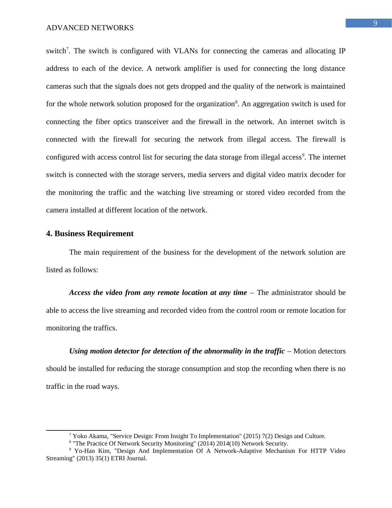
switch7. The switch is configured with VLANs for connecting the cameras and allocating IP
address to each of the device. A network amplifier is used for connecting the long distance
cameras such that the signals does not gets dropped and the quality of the network is maintained
for the whole network solution proposed for the organization8. An aggregation switch is used for
connecting the fiber optics transceiver and the firewall in the network. An internet switch is
connected with the firewall for securing the network from illegal access. The firewall is
configured with access control list for securing the data storage from illegal access9. The internet
switch is connected with the storage servers, media servers and digital video matrix decoder for
the monitoring the traffic and the watching live streaming or stored video recorded from the
camera installed at different location of the network.
4. Business Requirement
The main requirement of the business for the development of the network solution are
listed as follows:
Access the video from any remote location at any time – The administrator should be
able to access the live streaming and recorded video from the control room or remote location for
monitoring the traffics.
Using motion detector for detection of the abnormality in the traffic – Motion detectors
should be installed for reducing the storage consumption and stop the recording when there is no
traffic in the road ways.
7 Yoko Akama, "Service Design: From Insight To Implementation" (2015) 7(2) Design and Culture.
8 "The Practice Of Network Security Monitoring" (2014) 2014(10) Network Security.
9 Yo-Han Kim, "Design And Implementation Of A Network-Adaptive Mechanism For HTTP Video
Streaming" (2013) 35(1) ETRI Journal.
ADVANCED NETWORKS
switch7. The switch is configured with VLANs for connecting the cameras and allocating IP
address to each of the device. A network amplifier is used for connecting the long distance
cameras such that the signals does not gets dropped and the quality of the network is maintained
for the whole network solution proposed for the organization8. An aggregation switch is used for
connecting the fiber optics transceiver and the firewall in the network. An internet switch is
connected with the firewall for securing the network from illegal access. The firewall is
configured with access control list for securing the data storage from illegal access9. The internet
switch is connected with the storage servers, media servers and digital video matrix decoder for
the monitoring the traffic and the watching live streaming or stored video recorded from the
camera installed at different location of the network.
4. Business Requirement
The main requirement of the business for the development of the network solution are
listed as follows:
Access the video from any remote location at any time – The administrator should be
able to access the live streaming and recorded video from the control room or remote location for
monitoring the traffics.
Using motion detector for detection of the abnormality in the traffic – Motion detectors
should be installed for reducing the storage consumption and stop the recording when there is no
traffic in the road ways.
7 Yoko Akama, "Service Design: From Insight To Implementation" (2015) 7(2) Design and Culture.
8 "The Practice Of Network Security Monitoring" (2014) 2014(10) Network Security.
9 Yo-Han Kim, "Design And Implementation Of A Network-Adaptive Mechanism For HTTP Video
Streaming" (2013) 35(1) ETRI Journal.
Paraphrase This Document
Need a fresh take? Get an instant paraphrase of this document with our AI Paraphraser
10
ADVANCED NETWORKS
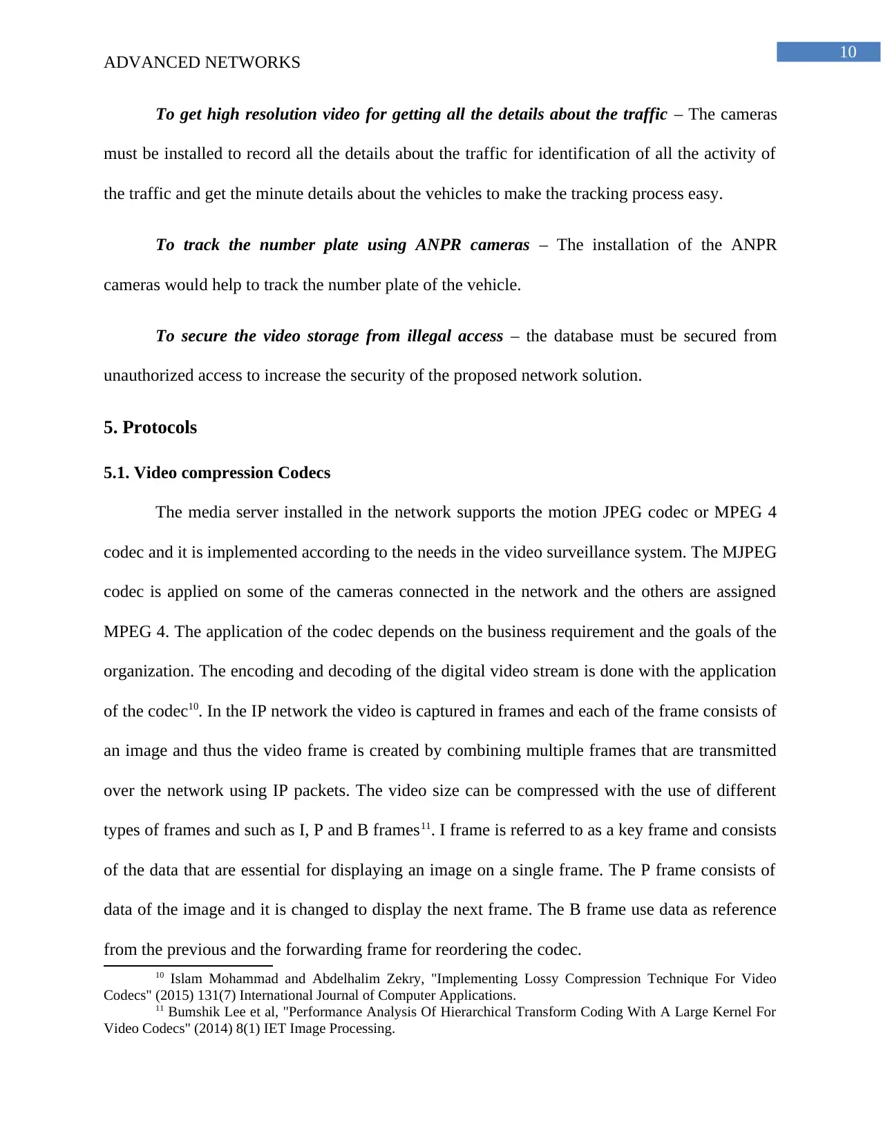
To get high resolution video for getting all the details about the traffic – The cameras
must be installed to record all the details about the traffic for identification of all the activity of
the traffic and get the minute details about the vehicles to make the tracking process easy.
To track the number plate using ANPR cameras – The installation of the ANPR
cameras would help to track the number plate of the vehicle.
To secure the video storage from illegal access – the database must be secured from
unauthorized access to increase the security of the proposed network solution.
5. Protocols
5.1. Video compression Codecs
The media server installed in the network supports the motion JPEG codec or MPEG 4
codec and it is implemented according to the needs in the video surveillance system. The MJPEG
codec is applied on some of the cameras connected in the network and the others are assigned
MPEG 4. The application of the codec depends on the business requirement and the goals of the
organization. The encoding and decoding of the digital video stream is done with the application
of the codec10. In the IP network the video is captured in frames and each of the frame consists of
an image and thus the video frame is created by combining multiple frames that are transmitted
over the network using IP packets. The video size can be compressed with the use of different
types of frames and such as I, P and B frames11. I frame is referred to as a key frame and consists
of the data that are essential for displaying an image on a single frame. The P frame consists of
data of the image and it is changed to display the next frame. The B frame use data as reference
from the previous and the forwarding frame for reordering the codec.
10 Islam Mohammad and Abdelhalim Zekry, "Implementing Lossy Compression Technique For Video
Codecs" (2015) 131(7) International Journal of Computer Applications.
11 Bumshik Lee et al, "Performance Analysis Of Hierarchical Transform Coding With A Large Kernel For
Video Codecs" (2014) 8(1) IET Image Processing.
ADVANCED NETWORKS
To get high resolution video for getting all the details about the traffic – The cameras
must be installed to record all the details about the traffic for identification of all the activity of
the traffic and get the minute details about the vehicles to make the tracking process easy.
To track the number plate using ANPR cameras – The installation of the ANPR
cameras would help to track the number plate of the vehicle.
To secure the video storage from illegal access – the database must be secured from
unauthorized access to increase the security of the proposed network solution.
5. Protocols
5.1. Video compression Codecs
The media server installed in the network supports the motion JPEG codec or MPEG 4
codec and it is implemented according to the needs in the video surveillance system. The MJPEG
codec is applied on some of the cameras connected in the network and the others are assigned
MPEG 4. The application of the codec depends on the business requirement and the goals of the
organization. The encoding and decoding of the digital video stream is done with the application
of the codec10. In the IP network the video is captured in frames and each of the frame consists of
an image and thus the video frame is created by combining multiple frames that are transmitted
over the network using IP packets. The video size can be compressed with the use of different
types of frames and such as I, P and B frames11. I frame is referred to as a key frame and consists
of the data that are essential for displaying an image on a single frame. The P frame consists of
data of the image and it is changed to display the next frame. The B frame use data as reference
from the previous and the forwarding frame for reordering the codec.
10 Islam Mohammad and Abdelhalim Zekry, "Implementing Lossy Compression Technique For Video
Codecs" (2015) 131(7) International Journal of Computer Applications.
11 Bumshik Lee et al, "Performance Analysis Of Hierarchical Transform Coding With A Large Kernel For
Video Codecs" (2014) 8(1) IET Image Processing.
11
ADVANCED NETWORKS
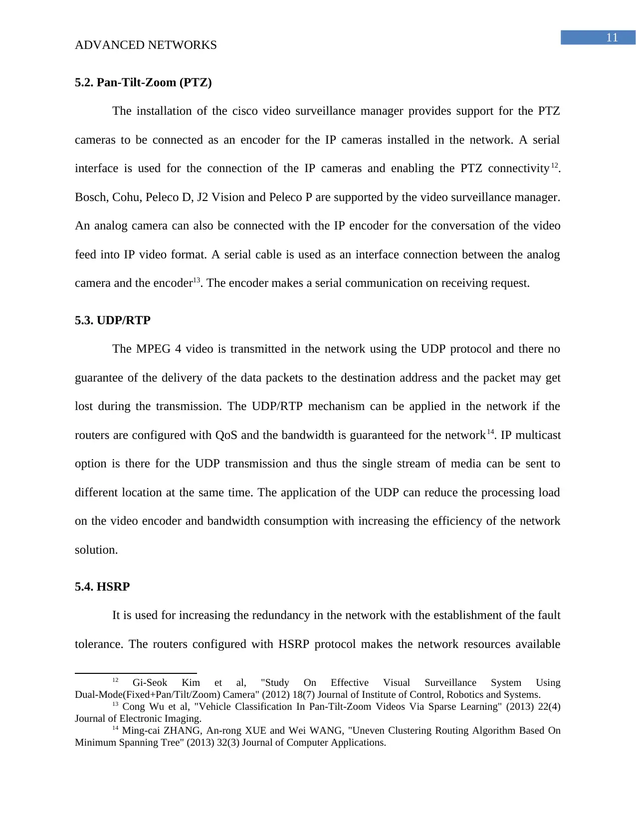
5.2. Pan-Tilt-Zoom (PTZ)
The installation of the cisco video surveillance manager provides support for the PTZ
cameras to be connected as an encoder for the IP cameras installed in the network. A serial
interface is used for the connection of the IP cameras and enabling the PTZ connectivity12.
Bosch, Cohu, Peleco D, J2 Vision and Peleco P are supported by the video surveillance manager.
An analog camera can also be connected with the IP encoder for the conversation of the video
feed into IP video format. A serial cable is used as an interface connection between the analog
camera and the encoder13. The encoder makes a serial communication on receiving request.
5.3. UDP/RTP
The MPEG 4 video is transmitted in the network using the UDP protocol and there no
guarantee of the delivery of the data packets to the destination address and the packet may get
lost during the transmission. The UDP/RTP mechanism can be applied in the network if the
routers are configured with QoS and the bandwidth is guaranteed for the network14. IP multicast
option is there for the UDP transmission and thus the single stream of media can be sent to
different location at the same time. The application of the UDP can reduce the processing load
on the video encoder and bandwidth consumption with increasing the efficiency of the network
solution.
5.4. HSRP
It is used for increasing the redundancy in the network with the establishment of the fault
tolerance. The routers configured with HSRP protocol makes the network resources available
12 Gi-Seok Kim et al, "Study On Effective Visual Surveillance System Using
Dual-Mode(Fixed+Pan/Tilt/Zoom) Camera" (2012) 18(7) Journal of Institute of Control, Robotics and Systems.
13 Cong Wu et al, "Vehicle Classification In Pan-Tilt-Zoom Videos Via Sparse Learning" (2013) 22(4)
Journal of Electronic Imaging.
14 Ming-cai ZHANG, An-rong XUE and Wei WANG, "Uneven Clustering Routing Algorithm Based On
Minimum Spanning Tree" (2013) 32(3) Journal of Computer Applications.
ADVANCED NETWORKS
5.2. Pan-Tilt-Zoom (PTZ)
The installation of the cisco video surveillance manager provides support for the PTZ
cameras to be connected as an encoder for the IP cameras installed in the network. A serial
interface is used for the connection of the IP cameras and enabling the PTZ connectivity12.
Bosch, Cohu, Peleco D, J2 Vision and Peleco P are supported by the video surveillance manager.
An analog camera can also be connected with the IP encoder for the conversation of the video
feed into IP video format. A serial cable is used as an interface connection between the analog
camera and the encoder13. The encoder makes a serial communication on receiving request.
5.3. UDP/RTP
The MPEG 4 video is transmitted in the network using the UDP protocol and there no
guarantee of the delivery of the data packets to the destination address and the packet may get
lost during the transmission. The UDP/RTP mechanism can be applied in the network if the
routers are configured with QoS and the bandwidth is guaranteed for the network14. IP multicast
option is there for the UDP transmission and thus the single stream of media can be sent to
different location at the same time. The application of the UDP can reduce the processing load
on the video encoder and bandwidth consumption with increasing the efficiency of the network
solution.
5.4. HSRP
It is used for increasing the redundancy in the network with the establishment of the fault
tolerance. The routers configured with HSRP protocol makes the network resources available
12 Gi-Seok Kim et al, "Study On Effective Visual Surveillance System Using
Dual-Mode(Fixed+Pan/Tilt/Zoom) Camera" (2012) 18(7) Journal of Institute of Control, Robotics and Systems.
13 Cong Wu et al, "Vehicle Classification In Pan-Tilt-Zoom Videos Via Sparse Learning" (2013) 22(4)
Journal of Electronic Imaging.
14 Ming-cai ZHANG, An-rong XUE and Wei WANG, "Uneven Clustering Routing Algorithm Based On
Minimum Spanning Tree" (2013) 32(3) Journal of Computer Applications.
⊘ This is a preview!⊘
Do you want full access?
Subscribe today to unlock all pages.
Trusted by 1+ million students worldwide
1 out of 18
Related Documents


Your All-in-One AI-Powered Toolkit for Academic Success.
+13062052269
info@desklib.com
Available 24*7 on WhatsApp / Email
![[object Object]](/_next/static/media/star-bottom.7253800d.svg)
Unlock your academic potential
Copyright © 2020–2026 A2Z Services. All Rights Reserved. Developed and managed by ZUCOL.