Analysis of Aerofoil Sections and Flight Forces in Subsonic Flight
VerifiedAdded on 2022/11/14
|13
|1838
|95
Homework Assignment
AI Summary
This document provides a comprehensive analysis of aerofoil sections and flight forces in subsonic flight, addressing key concepts such as lift, drag, thrust, and weight. It explores the four main forces acting on an aircraft and their impact on flight dynamics. The assignment delves into pitching moments, the role of horizontal tail planes in aircraft stability, and the effects of control surfaces like ailerons and rudders. It includes calculations related to aircraft weight, lift, thrust requirements, load factors, and stall speeds. The document further examines the relationship between bank angle, lift, and turning radius, providing detailed solutions to various problems related to flight maneuvers and aircraft performance. The solutions also cover the effects of flaps on stall speed and the importance of maneuvering speed, as well as the application of load factors to aircraft design limitations and flight safety. Finally, the assignment addresses the mechanics of banked turns, including how pilots maintain altitude and control aircraft direction.
1
Assignment 3: Aerofoil Sections and Flight Forces in Subsonic Flight
Name:
College:
Date:
Assignment 3: Aerofoil Sections and Flight Forces in Subsonic Flight
Name:
College:
Date:
Paraphrase This Document
Need a fresh take? Get an instant paraphrase of this document with our AI Paraphraser
2
TASK 1
Question 1
The four main forces acting on an aircraft:
i) Weight
This is as a result of the mass of the aircraft and the force of gravity. It is a product of the two
quantities and acts downwards. In equation form, it is given by:
W =mg
The total mass of the aircraft is contributed by the aircraft’s parts, fuel and any load attached
including passengers. The weight of the aircraft is usually distributed throughout the body
(Dingle & Tooley, 2013). However, for simplicity the weight is often thought of as acting
through the centre of gravity of the airplane.
ii) Lift
This is the force that is required to overcome the force of gravity in order to keep an aircraft
in air. It is mostly generated by the wings of the aircraft although all the every part of the
aircraft contributes some amount of lift. The direction of lift is perpendicular to the direction
of flight. The magnitude of the generated lift depends on factors such as the size, shape and
the velocity of the aircraft (Gudmundsson, 2013). The aircraft’s lift acts through the centre of
pressure which is a single point.
iii) Thrust
This is the force that propels an aircraft in the desired direction of motion. Thrust is produced
by the engines on the aircraft. The magnitude of the thrust produced is dependent on several
factors such as the type of the engine as well as the number of engines. Types of aircraft
engines include jet engines and turbine engines (Gudmundsson, 2013). The direction in
3
which the thrust force acts is also dependent on the mode of attachment on the aircraft’s
fuselage.
iv) Drag
This is the force that opposes the motion of the aircraft in the desired direction. This force is
caused by the resistance of air to the aircraft’s motion. The magnitude of the drag force is
affected by many factors such as the shape of the aircraft, the velocity of the aircraft and air
viscosity (Nicolai & Carichner, 2010). Just like lift, the drag force acts through the centre of
pressure of the aircraft.
Question 2
Question 3
a) Pitching moment
The pitching moment of an aircraft is defined as the torque resulting from the aerodynamic
force when applied at the aerodynamic centre instead of the centre of pressure. The centre of
pressure on an airfoil changes, moving forward as the angle of attack changes on a cambered
airfoil (Nicolai & Carichner, 2010). This makes the analysis of the aircraft’s dynamics
⊘ This is a preview!⊘
Do you want full access?
Subscribe today to unlock all pages.

Trusted by 1+ million students worldwide
4
difficult. However, for a cambered airfoil, if we imagine the lift to act through the
aerodynamic centre, the lift force moment change will be proportional to the square of the
airspeed. Dividing the moment with the dynamic pressure, the chord and the area of the
aerofoil gives the pitching moment coefficient. Unlike the centre of pressure, the pitching
coefficient only changes slightly with the angle of attack which eases the analysis of the
aircraft’s flight characteristics.
b)
The horizontal tail plane is also known as horizontal stabiliser. It helps to maintain stability of
the aircraft by enabling the adjustment of the centre of gravity and the centre of pressure
which result from changes in the aircraft characteristics such as speed, altitude and fuel
consumption.
c)
The horizontal tail plane generates a downward force that counters pitching moment
produced by an aircraft when it performs a normal nose-down motion. If the centre of gravity
is located further forward from the centre of pressure, the nose down moment will be greater
and correspondingly, the horizontal tail plane must generate more downward force to counter
the increased pitching moment (Nicolai & Carichner, 2010).
Paraphrase This Document
Need a fresh take? Get an instant paraphrase of this document with our AI Paraphraser
5
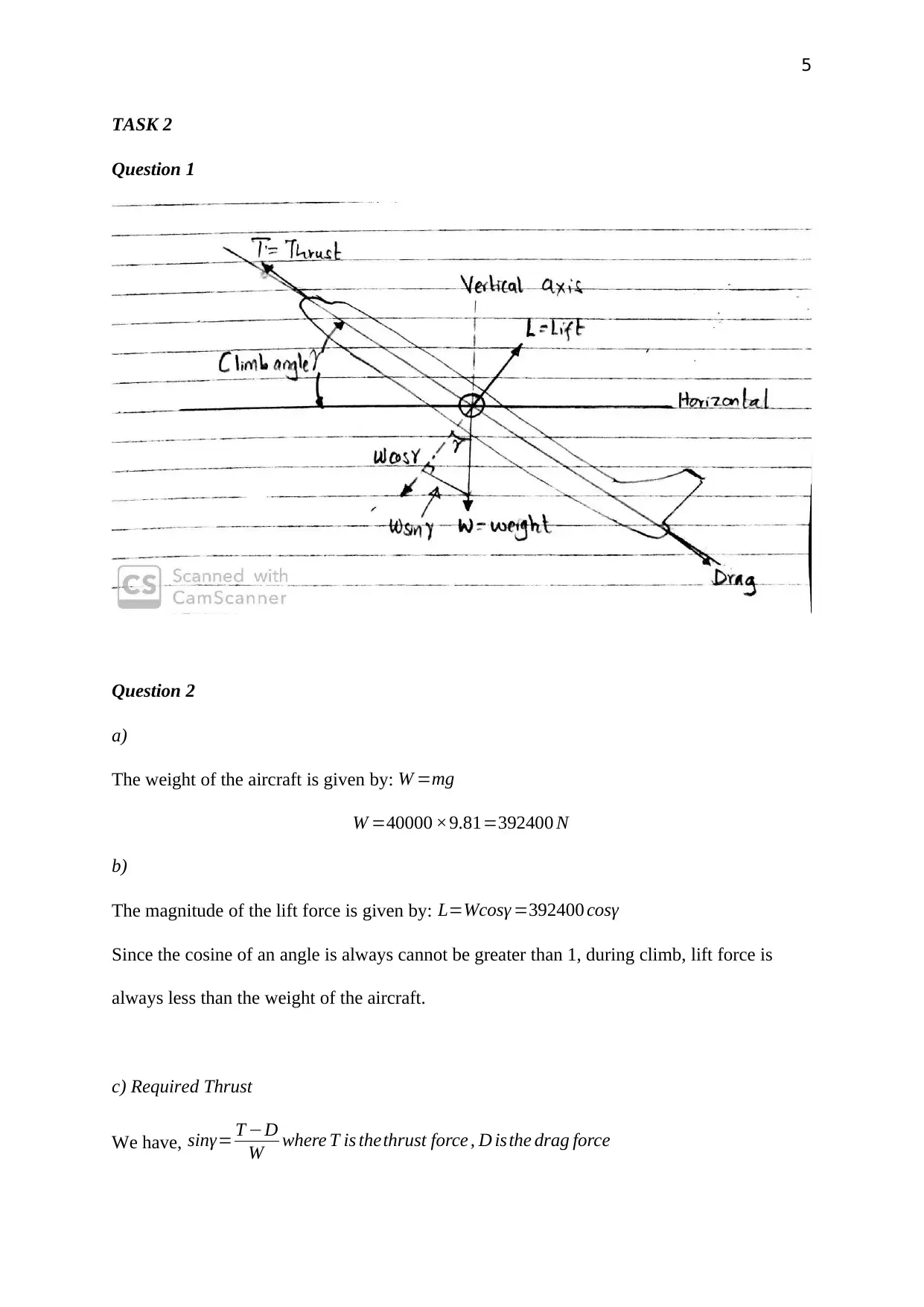
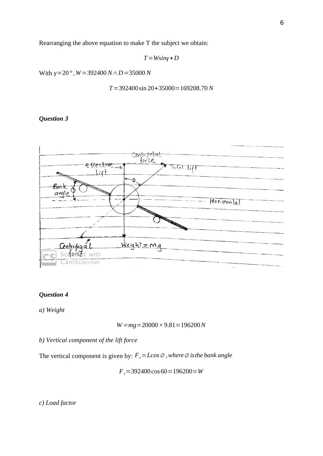
TASK 2
Question 1
Question 2
a)
The weight of the aircraft is given by: W =mg
W =40000 ×9.81=392400 N
b)
The magnitude of the lift force is given by: L=Wcosγ =392400 cosγ
Since the cosine of an angle is always cannot be greater than 1, during climb, lift force is
always less than the weight of the aircraft.
c) Required Thrust
We have, sinγ= T −D
W where T is thethrust force , D isthe drag force
6
Rearranging the above equation to make T the subject we obtain:
T =Wsinγ + D
With γ=20 ° , W =392400 N∧D=35000 N
T =392400 sin 20+35000=169208.70 N
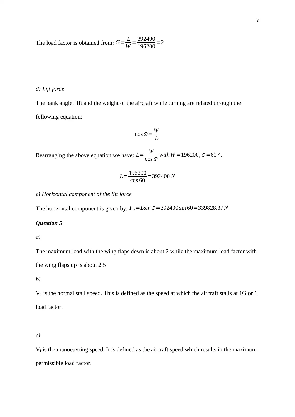
Question 3
Question 4
a) Weight
W =mg=20000 × 9.81=196200 N
b) Vertical component of the lift force
The vertical component is given by: Fv=Lcos ∅ , where ∅ isthe bank angle
Fv=392400 cos 60=196200=W
c) Load factor
⊘ This is a preview!⊘
Do you want full access?
Subscribe today to unlock all pages.

Trusted by 1+ million students worldwide
7
The load factor is obtained from: G= L
W = 392400
196200 =2
d) Lift force
The bank angle, lift and the weight of the aircraft while turning are related through the
following equation:
cos ∅ = W
L
Rearranging the above equation we have: L= W
cos ∅ withW =196200, ∅ =60 ° .
L= 196200
cos 60 =392400 N
e) Horizontal component of the lift force
The horizontal component is given by: Fh=Lsin∅ =392400 sin 60=339828.37 N
Question 5
a)
The maximum load with the wing flaps down is about 2 while the maximum load factor with
the wing flaps up is about 2.5
b)
V1 is the normal stall speed. This is defined as the speed at which the aircraft stalls at 1G or 1
load factor.
c)
Vf is the manoeuvring speed. It is defined as the aircraft speed which results in the maximum
permissible load factor.
Paraphrase This Document
Need a fresh take? Get an instant paraphrase of this document with our AI Paraphraser
8
d)
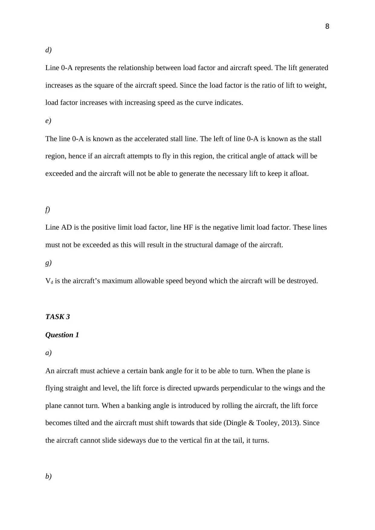
Line 0-A represents the relationship between load factor and aircraft speed. The lift generated
increases as the square of the aircraft speed. Since the load factor is the ratio of lift to weight,
load factor increases with increasing speed as the curve indicates.
e)
The line 0-A is known as the accelerated stall line. The left of line 0-A is known as the stall
region, hence if an aircraft attempts to fly in this region, the critical angle of attack will be
exceeded and the aircraft will not be able to generate the necessary lift to keep it afloat.
f)
Line AD is the positive limit load factor, line HF is the negative limit load factor. These lines
must not be exceeded as this will result in the structural damage of the aircraft.
g)
Vd is the aircraft’s maximum allowable speed beyond which the aircraft will be destroyed.
TASK 3
Question 1
a)
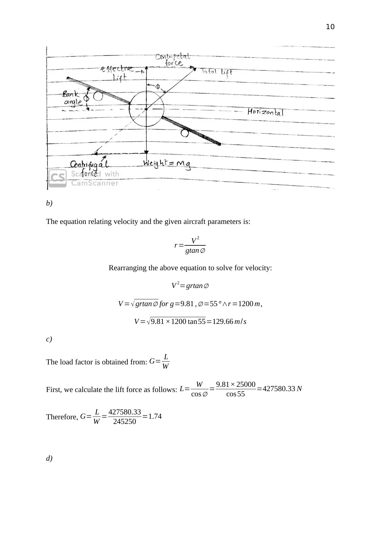
An aircraft must achieve a certain bank angle for it to be able to turn. When the plane is
flying straight and level, the lift force is directed upwards perpendicular to the wings and the
plane cannot turn. When a banking angle is introduced by rolling the aircraft, the lift force
becomes tilted and the aircraft must shift towards that side (Dingle & Tooley, 2013). Since
the aircraft cannot slide sideways due to the vertical fin at the tail, it turns.
b)
9
To roll an aircraft, the pilot uses the control stick to control the ailerons. The pilot uses the
control stick to raise one of the ailerons while the lowering the other. One of the wings will
then experience more lift than the other causing the aircraft to tilt (roll) towards one side.
c)
In order to maintain altitude and to prevent the aircraft from descending, the pilot must
increase the angle of attack of the wings. This is done to ensure that the vertical component of
the lift is high enough to keep the aircraft from descending.
d)
The ailerons are the control surfaces used for rolling and to introduce a banking angle into the
aircraft’s flight. To introduce banking, the pilot moves the control stick either left or right
depending on the desired direction of turning (Dingle & Tooley, 2013). The aircraft will then
tilt towards that direction. To restore the aircraft to level straight flying, the pilot turns the
stick in the opposite direction to that used to achieve rolling in order to reduce the bank angle
to zero.
Question 2
a)
⊘ This is a preview!⊘
Do you want full access?
Subscribe today to unlock all pages.

Trusted by 1+ million students worldwide
10
b)
The equation relating velocity and the given aircraft parameters is:
r = V 2
gtan∅
Rearranging the above equation to solve for velocity:
V 2=grtan∅
V = √grtan∅ for g=9.81 , ∅ =55 °∧r =1200 m,
V = √9.81 ×1200 tan55=129.66 m/s
c)
The load factor is obtained from: G= L
W
First, we calculate the lift force as follows: L= W
cos ∅ = 9.81× 25000
cos 55 =427580.33 N
Therefore, G= L
W = 427580.33
245250 =1.74
d)
Paraphrase This Document
Need a fresh take? Get an instant paraphrase of this document with our AI Paraphraser
11
In order to ensure that the aircraft maintains the same altitude while turning, the pilot pulls
the stick backwards which then increases the angle of attack and therefore the lift
(Administration, 2011). This is because if a bank angle is introduced, then the lift should be
increased to avoid imbalance of the aircraft weight and lift which would cause the aircraft to
descend.
e)
When the aircraft is performing a banked turn, the elevator is used to increase lift and to
enable a tighter turn. To increase lift, the elevator is moved upwards. The pilot pushes the
control stick backward to move the elevator upwards (Administration, 2011). Raising the
elevators causes the aircraft’s nose to pitch up which increases the angle of attack and lift.
f)
When an aircraft is turning, it tends yaw towards the direction opposite to that of the roll.
This is uncomfortable and can cause instability. Therefore, the pilot uses the rudder to
minimize these effects. If the aircraft rolls towards the left, the pilot uses the left rudder. If it
rolls towards the right, the opposite rudder is used (Administration, 2011).
Question 3
a)
12
b)
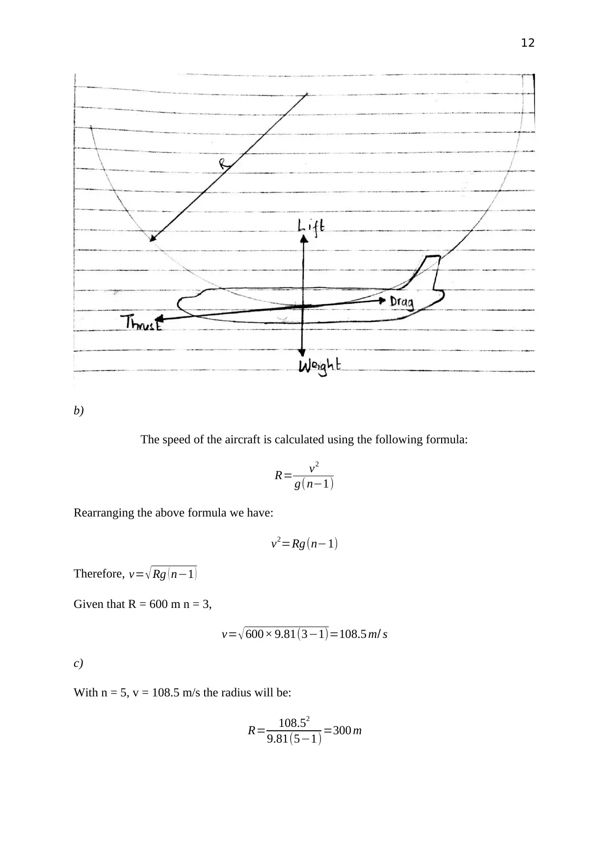
The speed of the aircraft is calculated using the following formula:
R= v2
g(n−1)
Rearranging the above formula we have:
v2=Rg(n−1)
Therefore, v= √ Rg ( n−1 )
Given that R = 600 m n = 3,
v= √600× 9.81(3−1)=108.5 m/ s
c)
With n = 5, v = 108.5 m/s the radius will be:
R= 108.52
9.81(5−1)=300 m
b)
The speed of the aircraft is calculated using the following formula:
R= v2
g(n−1)
Rearranging the above formula we have:
v2=Rg(n−1)
Therefore, v= √ Rg ( n−1 )
Given that R = 600 m n = 3,
v= √600× 9.81(3−1)=108.5 m/ s
c)
With n = 5, v = 108.5 m/s the radius will be:
R= 108.52
9.81(5−1)=300 m
⊘ This is a preview!⊘
Do you want full access?
Subscribe today to unlock all pages.

Trusted by 1+ million students worldwide
1 out of 13
Related Documents
Your All-in-One AI-Powered Toolkit for Academic Success.
+13062052269
info@desklib.com
Available 24*7 on WhatsApp / Email
![[object Object]](/_next/static/media/star-bottom.7253800d.svg)
Unlock your academic potential
Copyright © 2020–2026 A2Z Services. All Rights Reserved. Developed and managed by ZUCOL.


