INFS600 Assignment: Modeling AIK9 Limited Clinic System with UML
VerifiedAdded on 2023/06/15
|13
|2567
|390
Report
AI Summary
This assignment provides a comprehensive analysis of the AIK9 Limited Clinic System using UML diagrams. It identifies key stakeholders such as dog owners, veterinary doctors, and senior veterinarians, and elicits their requirements. The document includes a use case diagram illustrating the interactions between users and the system, along with a detailed use case specification for creating a new support case. Furthermore, it models system interactivity through an activity diagram, presents a domain model using a class diagram, and illustrates behavioral aspects with sequence and state transition diagrams. The assignment offers a thorough understanding of the system's architecture and functionality.

Running head: UML DIAGRAMS
UML Diagrams: AIK9 Limited Clinic System
Name of the Student:
Name of the University:
Author Note
UML Diagrams: AIK9 Limited Clinic System
Name of the Student:
Name of the University:
Author Note
Paraphrase This Document
Need a fresh take? Get an instant paraphrase of this document with our AI Paraphraser
1
UML DIAGRAMS
Table of Contents
Question 1 Identify Stakeholders & Elicit Requirements................................................................2
Question 2 Identify Interactions between Users and the Clinic System..........................................3
Use Case Identification and History..........................................................................................6
Use Case ID & Name:..............................................................................................................6
Version:...................................................................................................................................6
Objective:................................................................................................................................6
Created by:..............................................................................................................................6
Date:............................................................................................................................................6
Actors & Goals:.......................................................................................................................6
Stakeholders...........................................................................................................................6
Trigger:....................................................................................................................................6
Preconditions.............................................................................................................................6
Main Success Flow.....................................................................................................................6
User Actions............................................................................................................................6
System Actions.......................................................................................................................6
User Actions............................................................................................................................6
System Actions.......................................................................................................................6
Post conditions...........................................................................................................................7
Other Notes (Assumptions, Issues,).........................................................................................7
Question 3 Model System Interactivity...........................................................................................8
Question 4 Domain Model...............................................................................................................9
Question 5 Behavioral Model..........................................................................................................9
Bibliography..................................................................................................................................11
2
UML DIAGRAMS
Question 1 Identify Stakeholders & Elicit Requirements
a) The actors associated with the AIK9 Limited Clinic System are the owner of the dogs and the
veterinary doctors in the clinic. In addition to this, the senior veterinary is also associated with
the system and can play the role of the administrator to a certain level.
Owner - The owner controls the AIK9 machines and interacts with the system when they face
any type of problems with the machines. The user interacts with system and only the name of the
user is recorded in the system. The owner then enters the details of the problem to the system.
The Veterinary – The looks for the registered cases in the system. After checking the case the
veterinary looks for the cases which are still open and not closed and takes up the case. When a
vet takes up case they can only comment on the case and they are not eligible to create or delete
a case.
Senior veterinary - the senior veterinary is provided with all the facilities of the veterinary,
however the senior veterinary is provided with some additional access to delete the case. The
senior vet also monitors the performances of the other veterinaries linked with the system. They
are also involved with the management of the workload in the system.
b) The set of requirement that the system should fulfill for each of the actor described previously
are:
Owner
The owner should be able to register themselves into the system
The owner should be able to register a case into the system by providing a short
description of the problem and providing the entire description of the problem below the
short description.
The owner should be able to respond to the comments made on their cases.
The owners should also be provided with the option of making comments on the cases
that are already closed by the system.
The Veterinary
⊘ This is a preview!⊘
Do you want full access?
Subscribe today to unlock all pages.
Trusted by 1+ million students worldwide

3
UML DIAGRAMS
The veterinary should be able to interact with the system, with an account.
The veterinary should be able to view the cases of different categories, in new, closed and
open.
The veterinary should be provided with the option to comment on the case.
The veterinary should be able to report to the senior vet.
The senior veterinary
The senior veterinary should be provided with the options of administrative option.
The senior veterinary can monitor the other vets who are associated with the systems.
They should be able to manage the workload on the veterinary who are connected to the
system.
The senior vet should also be provided with the option of deleting the case in case the
case is irrelevant
Question 2 Identify Interactions between Users and the Clinic System
a) The Use case diagram of the AIK9 Limited Clinic System is provided below:
Figure 1: Use Case Diagram of the AIK9 Limited Clinic System
Paraphrase This Document
Need a fresh take? Get an instant paraphrase of this document with our AI Paraphraser
4
UML DIAGRAMS
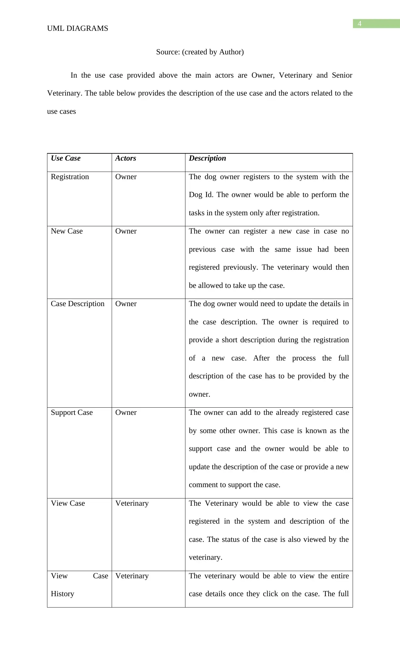
Source: (created by Author)
In the use case provided above the main actors are Owner, Veterinary and Senior
Veterinary. The table below provides the description of the use case and the actors related to the
use cases
Use Case Actors Description
Registration Owner The dog owner registers to the system with the
Dog Id. The owner would be able to perform the
tasks in the system only after registration.
New Case Owner The owner can register a new case in case no
previous case with the same issue had been
registered previously. The veterinary would then
be allowed to take up the case.
Case Description Owner The dog owner would need to update the details in
the case description. The owner is required to
provide a short description during the registration
of a new case. After the process the full
description of the case has to be provided by the
owner.
Support Case Owner The owner can add to the already registered case
by some other owner. This case is known as the
support case and the owner would be able to
update the description of the case or provide a new
comment to support the case.
View Case Veterinary The Veterinary would be able to view the case
registered in the system and description of the
case. The status of the case is also viewed by the
veterinary.
View Case
History
Veterinary The veterinary would be able to view the entire
case details once they click on the case. The full
UML DIAGRAMS
Source: (created by Author)
In the use case provided above the main actors are Owner, Veterinary and Senior
Veterinary. The table below provides the description of the use case and the actors related to the
use cases
Use Case Actors Description
Registration Owner The dog owner registers to the system with the
Dog Id. The owner would be able to perform the
tasks in the system only after registration.
New Case Owner The owner can register a new case in case no
previous case with the same issue had been
registered previously. The veterinary would then
be allowed to take up the case.
Case Description Owner The dog owner would need to update the details in
the case description. The owner is required to
provide a short description during the registration
of a new case. After the process the full
description of the case has to be provided by the
owner.
Support Case Owner The owner can add to the already registered case
by some other owner. This case is known as the
support case and the owner would be able to
update the description of the case or provide a new
comment to support the case.
View Case Veterinary The Veterinary would be able to view the case
registered in the system and description of the
case. The status of the case is also viewed by the
veterinary.
View Case
History
Veterinary The veterinary would be able to view the entire
case details once they click on the case. The full
5
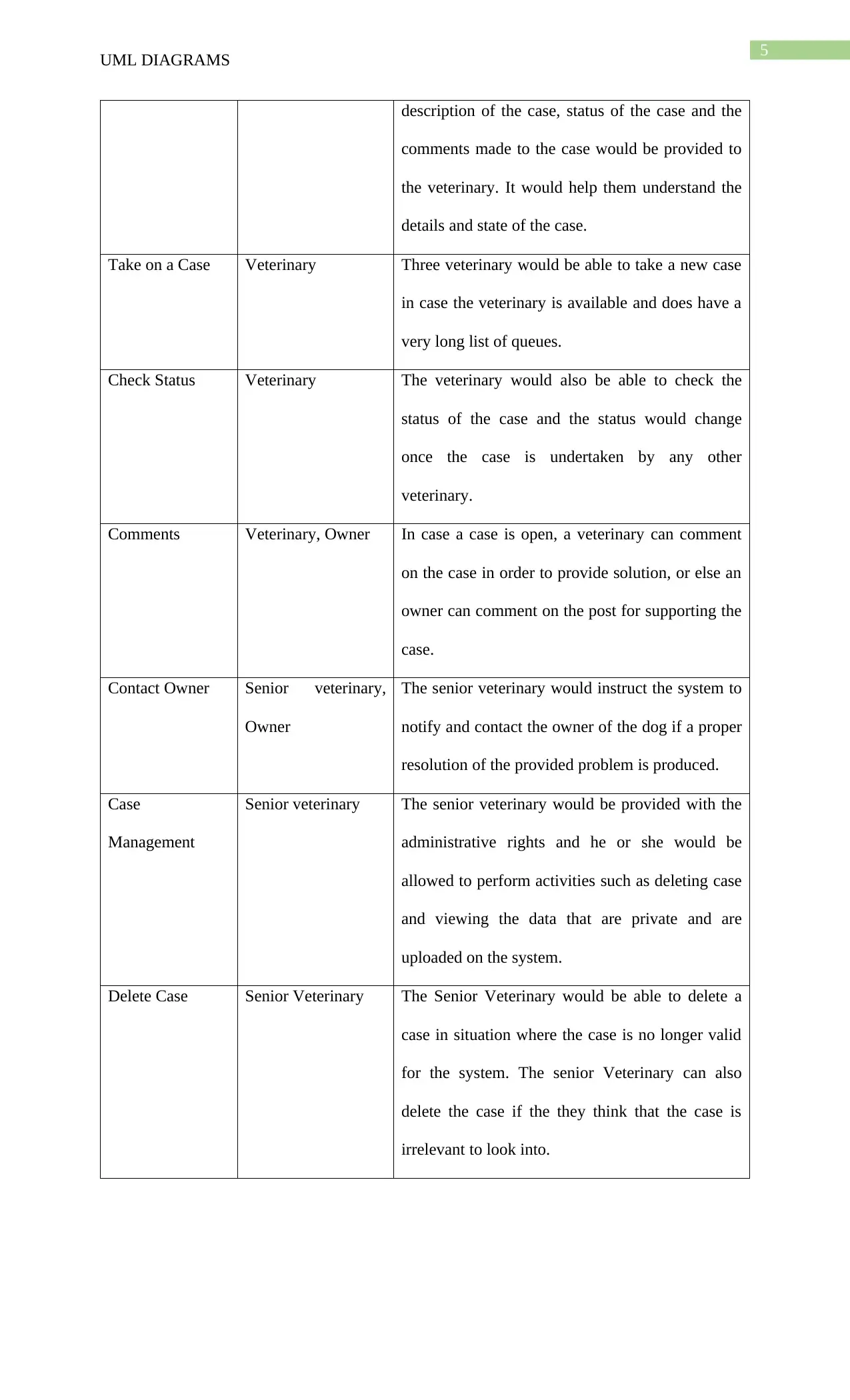
UML DIAGRAMS
description of the case, status of the case and the
comments made to the case would be provided to
the veterinary. It would help them understand the
details and state of the case.
Take on a Case Veterinary Three veterinary would be able to take a new case
in case the veterinary is available and does have a
very long list of queues.
Check Status Veterinary The veterinary would also be able to check the
status of the case and the status would change
once the case is undertaken by any other
veterinary.
Comments Veterinary, Owner In case a case is open, a veterinary can comment
on the case in order to provide solution, or else an
owner can comment on the post for supporting the
case.
Contact Owner Senior veterinary,
Owner
The senior veterinary would instruct the system to
notify and contact the owner of the dog if a proper
resolution of the provided problem is produced.
Case
Management
Senior veterinary The senior veterinary would be provided with the
administrative rights and he or she would be
allowed to perform activities such as deleting case
and viewing the data that are private and are
uploaded on the system.
Delete Case Senior Veterinary The Senior Veterinary would be able to delete a
case in situation where the case is no longer valid
for the system. The senior Veterinary can also
delete the case if the they think that the case is
irrelevant to look into.
⊘ This is a preview!⊘
Do you want full access?
Subscribe today to unlock all pages.
Trusted by 1+ million students worldwide
6
UML DIAGRAMS
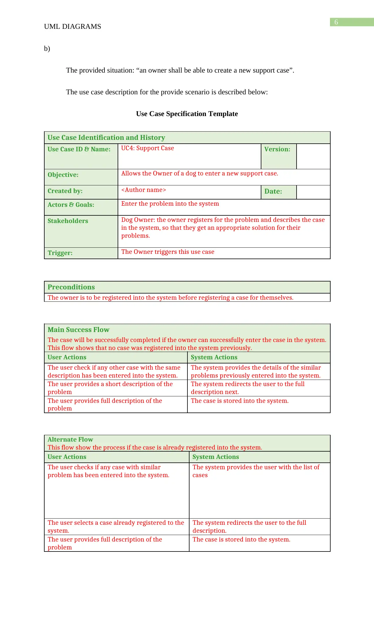
b)
The provided situation: “an owner shall be able to create a new support case”.
The use case description for the provide scenario is described below:
Use Case Specification Template
Use Case Identification and History
Use Case ID & Name: UC4: Support Case Version:
Objective: Allows the Owner of a dog to enter a new support case.
Created by: <Author name> Date:
Actors & Goals: Enter the problem into the system
Stakeholders Dog Owner: the owner registers for the problem and describes the case
in the system, so that they get an appropriate solution for their
problems.
Trigger: The Owner triggers this use case
Preconditions
The owner is to be registered into the system before registering a case for themselves.
Main Success Flow
The case will be successfully completed if the owner can successfully enter the case in the system.
This flow shows that no case was registered into the system previously.
User Actions System Actions
The user check if any other case with the same
description has been entered into the system.
The system provides the details of the similar
problems previously entered into the system.
The user provides a short description of the
problem
The system redirects the user to the full
description next.
The user provides full description of the
problem
The case is stored into the system.
Alternate Flow
This flow show the process if the case is already registered into the system.
User Actions System Actions
The user checks if any case with similar
problem has been entered into the system.
The system provides the user with the list of
cases
The user selects a case already registered to the
system.
The system redirects the user to the full
description.
The user provides full description of the
problem
The case is stored into the system.
UML DIAGRAMS
b)
The provided situation: “an owner shall be able to create a new support case”.
The use case description for the provide scenario is described below:
Use Case Specification Template
Use Case Identification and History
Use Case ID & Name: UC4: Support Case Version:
Objective: Allows the Owner of a dog to enter a new support case.
Created by: <Author name> Date:
Actors & Goals: Enter the problem into the system
Stakeholders Dog Owner: the owner registers for the problem and describes the case
in the system, so that they get an appropriate solution for their
problems.
Trigger: The Owner triggers this use case
Preconditions
The owner is to be registered into the system before registering a case for themselves.
Main Success Flow
The case will be successfully completed if the owner can successfully enter the case in the system.
This flow shows that no case was registered into the system previously.
User Actions System Actions
The user check if any other case with the same
description has been entered into the system.
The system provides the details of the similar
problems previously entered into the system.
The user provides a short description of the
problem
The system redirects the user to the full
description next.
The user provides full description of the
problem
The case is stored into the system.
Alternate Flow
This flow show the process if the case is already registered into the system.
User Actions System Actions
The user checks if any case with similar
problem has been entered into the system.
The system provides the user with the list of
cases
The user selects a case already registered to the
system.
The system redirects the user to the full
description.
The user provides full description of the
problem
The case is stored into the system.
Paraphrase This Document
Need a fresh take? Get an instant paraphrase of this document with our AI Paraphraser
7
UML DIAGRAMS
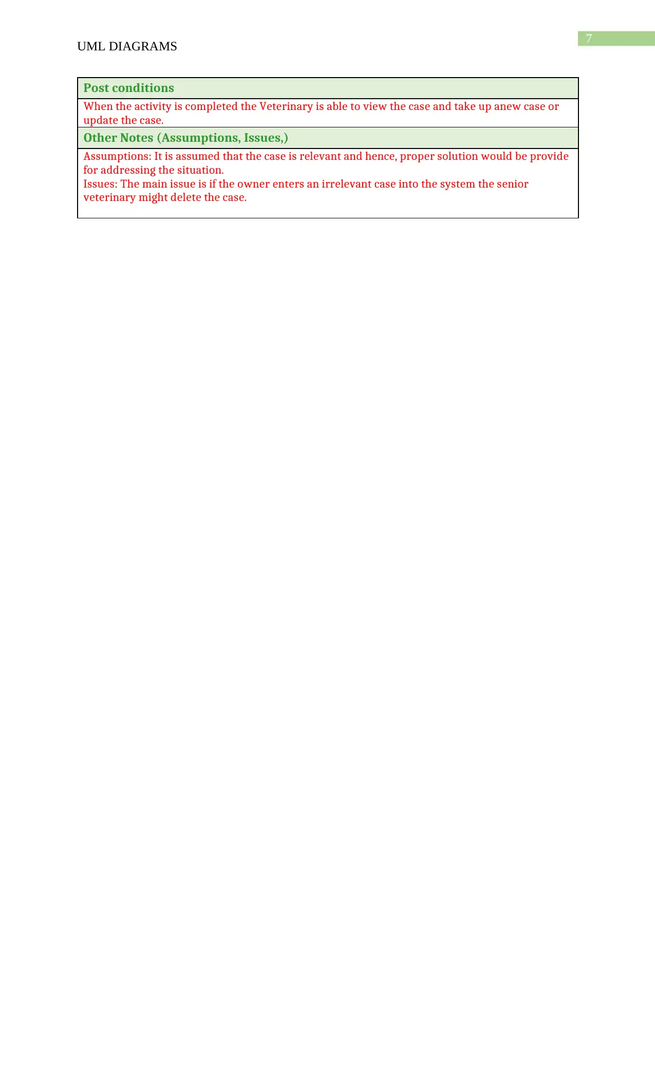
Post conditions
When the activity is completed the Veterinary is able to view the case and take up anew case or
update the case.
Other Notes (Assumptions, Issues,)
Assumptions: It is assumed that the case is relevant and hence, proper solution would be provide
for addressing the situation.
Issues: The main issue is if the owner enters an irrelevant case into the system the senior
veterinary might delete the case.
UML DIAGRAMS
Post conditions
When the activity is completed the Veterinary is able to view the case and take up anew case or
update the case.
Other Notes (Assumptions, Issues,)
Assumptions: It is assumed that the case is relevant and hence, proper solution would be provide
for addressing the situation.
Issues: The main issue is if the owner enters an irrelevant case into the system the senior
veterinary might delete the case.
8
UML DIAGRAMS
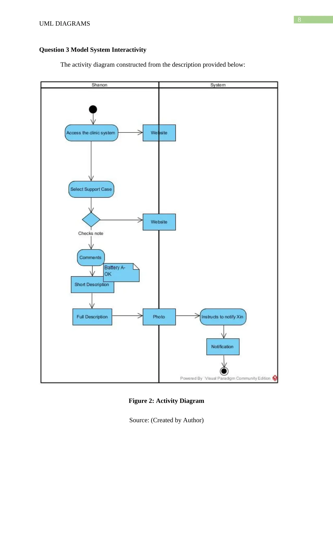
Question 3 Model System Interactivity
The activity diagram constructed from the description provided below:
Figure 2: Activity Diagram
Source: (Created by Author)
UML DIAGRAMS
Question 3 Model System Interactivity
The activity diagram constructed from the description provided below:
Figure 2: Activity Diagram
Source: (Created by Author)
⊘ This is a preview!⊘
Do you want full access?
Subscribe today to unlock all pages.
Trusted by 1+ million students worldwide

9
UML DIAGRAMS
Question 4 Domain Model
The class Diagram for the AIK9 Limited Clinic System is provided below:
Figure 3: Class Diagram of AIK9 Limited Clinic System
Source: (created by Author)
Question 5 Behavioral Model
a) The provided situation is “Vet transferring a case from his own queue to the other vet”.
The sequence Diagram for the provide situation is provided below:
Figure 4: Sequence Diagram
Source: (created by Author)
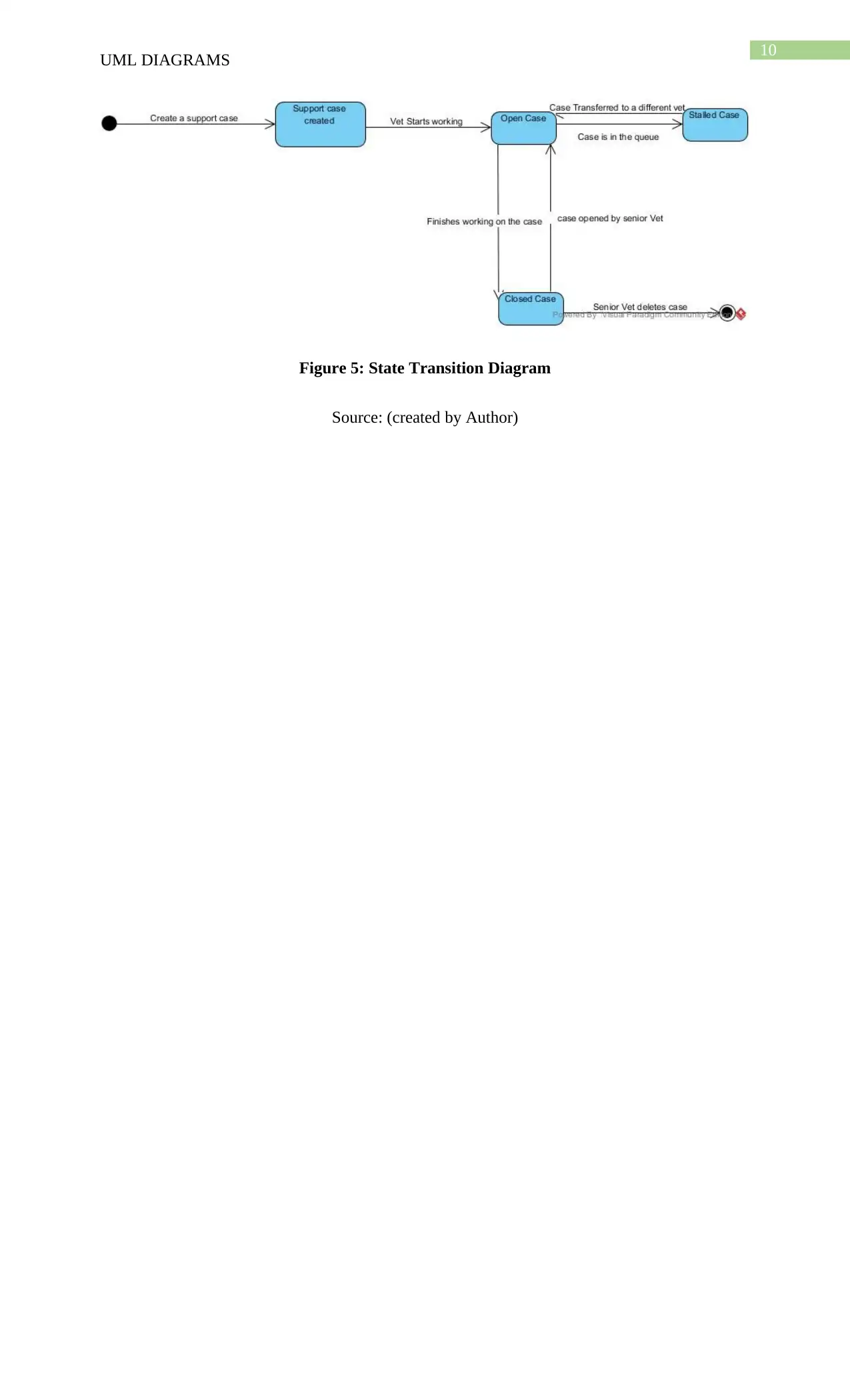
b) The state transition diagram for the support case is provided below:
UML DIAGRAMS
Question 4 Domain Model
The class Diagram for the AIK9 Limited Clinic System is provided below:
Figure 3: Class Diagram of AIK9 Limited Clinic System
Source: (created by Author)
Question 5 Behavioral Model
a) The provided situation is “Vet transferring a case from his own queue to the other vet”.
The sequence Diagram for the provide situation is provided below:
Figure 4: Sequence Diagram
Source: (created by Author)
b) The state transition diagram for the support case is provided below:
Paraphrase This Document
Need a fresh take? Get an instant paraphrase of this document with our AI Paraphraser
10
UML DIAGRAMS
Figure 5: State Transition Diagram
Source: (created by Author)
UML DIAGRAMS
Figure 5: State Transition Diagram
Source: (created by Author)
11
UML DIAGRAMS
Bibliography
Alreshidi, E., Mourshed, M. and Rezgui, Y., 2015. Cloud-based BIM governance platform
requirements and specifications: Software engineering approach using BPMN and UML. Journal
of Computing in Civil Engineering, 30(4), p.04015063.
Alvin, C., Peterson, B. and Mukhopadhyay, S., 2017, April. StaticGen: Static Generation of
UML Sequence Diagrams. In International Conference on Fundamental Approaches to Software
Engineering (pp. 173-190). Springer, Berlin, Heidelberg.
Blekhman, A., Wachs, J.P. and Dori, D., 2015. Model-Based System Specification With
Tesperanto: Readable Text From Formal Graphics. IEEE Transactions on Systems, Man, and
Cybernetics: Systems, 45(11), pp.1448-1458.
De Paepe, D., Thijs, G., Buyle, R., Verborgh, R. and Mannens, E., 2017, May. Automated UML-
Based Ontology Generation in OSLO 2. In European Semantic Web Conference (pp. 93-97).
Springer, Cham.
Decker, M.J., Swartz, K., Collard, M.L. and Maletic, J.I., 2016, October. A tool for efficiently
reverse engineering accurate UML class diagrams. In Software Maintenance and Evolution
(ICSME), 2016 IEEE International Conference on (pp. 607-609). IEEE.
Doherty, B. and Cheng, B.H., 2015. UML Modeling for Visually-Impaired Persons. In
HuFaMo@ MoDELS (pp. 4-10).
Gladisch, S., Kister, U., Tominski, C., Dachselt, R. and Schumann, H., 2015. Mapping Tasks to
Interactions for Graph Exploration and Graph Editing on Interactive Surfaces. arXiv preprint
arXiv:1504.07844.
Gupta, A., Tripathi, A. and Kuswaha, D.S., 2015. Use Case Based Approach to Analyze
Software Change Impact and Its Regression Test Effort Estimation. In Advanced Computer and
Communication Engineering Technology (pp. 1057-1067). Springer, Cham.
Guskov, G. and Namestnikov, A., 2017. Ontological mapping for conceptual models of software
system. In Proceedings of Seventh Conference on OSTIS (pp. 111-117).
Ma, W.M. and Lee, J., 2015. STUDY ON APPLYING AGILE PROJECT MANAGEMENT
AND UML FOR WEBSITE DEVELPOMENT-E-FLOWER STORE AS EXAMPLE.
⊘ This is a preview!⊘
Do you want full access?
Subscribe today to unlock all pages.
Trusted by 1+ million students worldwide
1 out of 13
Related Documents


Your All-in-One AI-Powered Toolkit for Academic Success.
+13062052269
info@desklib.com
Available 24*7 on WhatsApp / Email
![[object Object]](/_next/static/media/star-bottom.7253800d.svg)
Unlock your academic potential
Copyright © 2020–2025 A2Z Services. All Rights Reserved. Developed and managed by ZUCOL.