Status Report on Air-Conditioning at Menara TM Lift Motor Rooms
VerifiedAdded on 2021/04/29
|15
|2803
|245
Report
AI Summary
This report, prepared by Sinar Teknik Urusharta Sdn Bhd in September 2020, provides an assessment of the air-conditioning systems in the lift motor rooms of Menara Telekom Malaysia (Menara TM). The objective is to update the current status of air-conditioning for lift motor room Level 52 and lift motor room Level 58. The report details the equipment, including split units (York and ACSON) and fan coil units (York and Carrier), their ages, and performance. The report identifies several issues, including aging equipment, excessive distances between indoor and outdoor units of split systems, and poor equipment location hindering maintenance. The report highlights specific component failures such as compressor faults, motor issues, and valve problems, leading to reduced cooling capacity and potential disruptions to lift operations. Tables summarize the status of each unit, including cooling capacity and observed issues. The report concludes by analyzing root causes, including aging, distance between split unit components, and the location of fan coil units, impacting overall cooling efficiency and equipment lifespan.
REPORT ON STATUS OF AIR-CONDITIONER AT LIFT MOTOR ROOM LEVEL 52 &
LEVEL 58 AT MENARA TELEKOM MALAYSIA (MTM)
LEVEL 58 AT MENARA TELEKOM MALAYSIA (MTM)
Paraphrase This Document
Need a fresh take? Get an instant paraphrase of this document with our AI Paraphraser
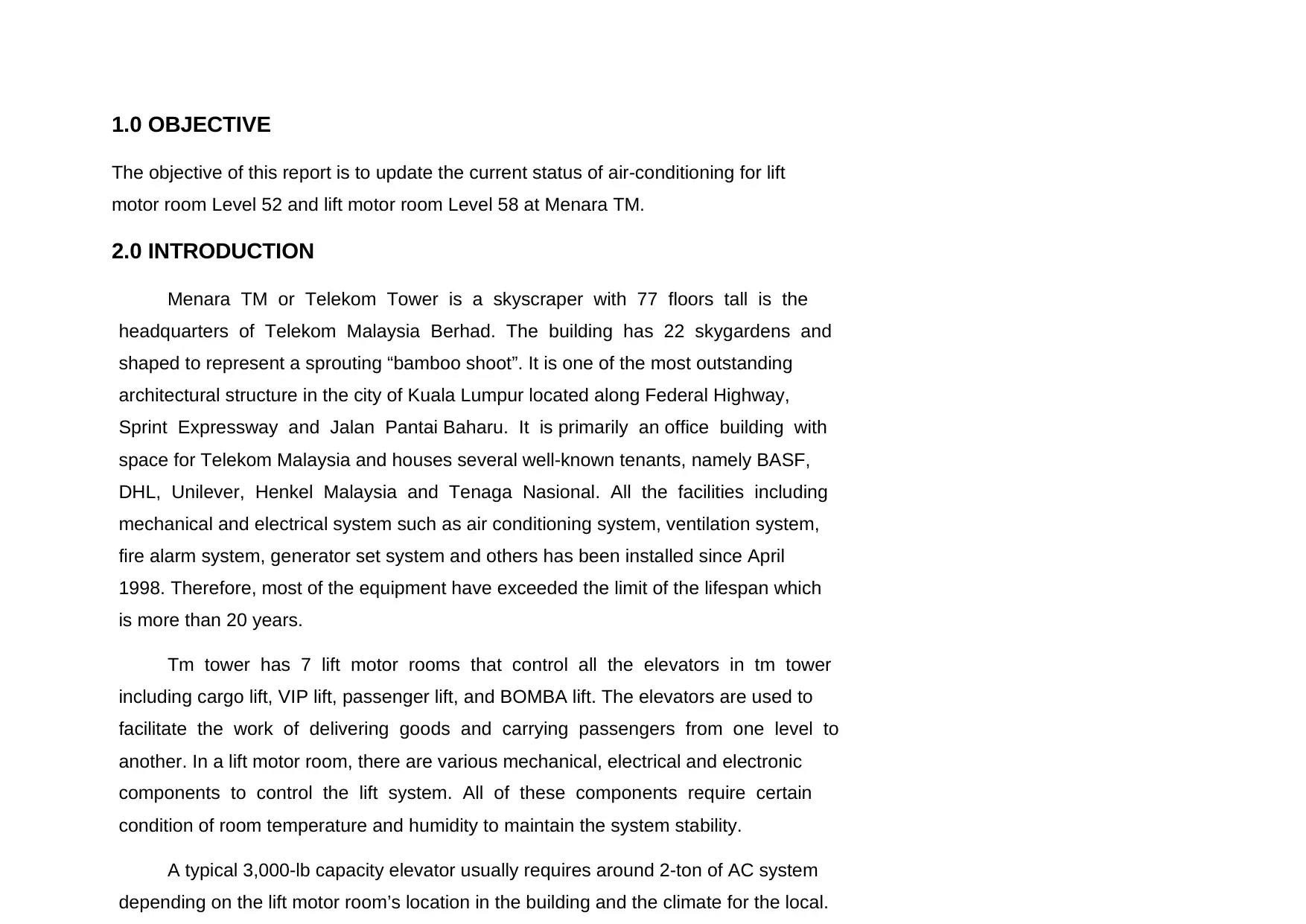
1.0 OBJECTIVE
The objective of this report is to update the current status of air-conditioning for lift
motor room Level 52 and lift motor room Level 58 at Menara TM.
2.0 INTRODUCTION
Menara TM or Telekom Tower is a skyscraper with 77 floors tall is the
headquarters of Telekom Malaysia Berhad. The building has 22 skygardens and
shaped to represent a sprouting “bamboo shoot”. It is one of the most outstanding
architectural structure in the city of Kuala Lumpur located along Federal Highway,
Sprint Expressway and Jalan Pantai Baharu. It is primarily an office building with
space for Telekom Malaysia and houses several well-known tenants, namely BASF,
DHL, Unilever, Henkel Malaysia and Tenaga Nasional. All the facilities including
mechanical and electrical system such as air conditioning system, ventilation system,
fire alarm system, generator set system and others has been installed since April
1998. Therefore, most of the equipment have exceeded the limit of the lifespan which
is more than 20 years.
Tm tower has 7 lift motor rooms that control all the elevators in tm tower
including cargo lift, VIP lift, passenger lift, and BOMBA lift. The elevators are used to
facilitate the work of delivering goods and carrying passengers from one level to
another. In a lift motor room, there are various mechanical, electrical and electronic
components to control the lift system. All of these components require certain
condition of room temperature and humidity to maintain the system stability.
A typical 3,000-lb capacity elevator usually requires around 2-ton of AC system
depending on the lift motor room’s location in the building and the climate for the local.
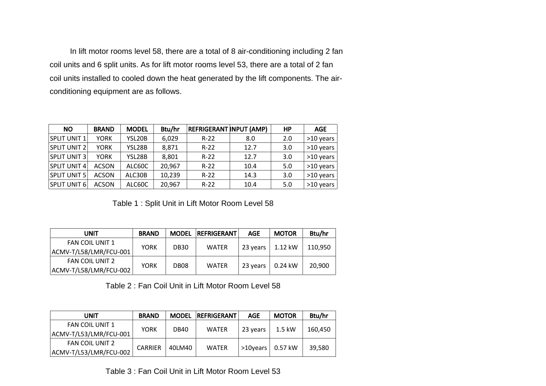
In lift motor rooms level 58, there are a total of 8 air-conditioning including 2 fan
coil units and 6 split units. As for lift motor rooms level 53, there are a total of 2 fan
coil units installed to cooled down the heat generated by the lift components. The air-
conditioning equipment are as follows.
Table 1 : Split Unit in Lift Motor Room Level 58
Table 2 : Fan Coil Unit in Lift Motor Room Level 58
Table 3 : Fan Coil Unit in Lift Motor Room Level 53
NO BRAND MODEL Btu/hr REFRIGERANT INPUT (AMP) HP AGE
SPLIT UNIT 1 YORK YSL20B 6,029 R-22 8.0 2.0 >10 years
SPLIT UNIT 2 YORK YSL28B 8,871 R-22 12.7 3.0 >10 years
SPLIT UNIT 3 YORK YSL28B 8,801 R-22 12.7 3.0 >10 years
SPLIT UNIT 4 ACSON ALC60C 20,967 R-22 10.4 5.0 >10 years
SPLIT UNIT 5 ACSON ALC30B 10,239 R-22 14.3 3.0 >10 years
SPLIT UNIT 6 ACSON ALC60C 20,967 R-22 10.4 5.0 >10 years
UNIT BRAND MODEL REFRIGERANT AGE MOTOR Btu/hr
FAN COIL UNIT 1
ACMV-T/L58/LMR/FCU-001 YORK DB30 WATER 23 years 1.12 kW 110,950
FAN COIL UNIT 2
ACMV-T/L58/LMR/FCU-002 YORK DB08 WATER 23 years 0.24 kW 20,900
UNIT BRAND MODEL REFRIGERANT AGE MOTOR Btu/hr
FAN COIL UNIT 1
ACMV-T/L53/LMR/FCU-001 YORK DB40 WATER 23 years 1.5 kW 160,450
FAN COIL UNIT 2
ACMV-T/L53/LMR/FCU-002 CARRIER 40LM40 WATER >10years 0.57 kW 39,580
⊘ This is a preview!⊘
Do you want full access?
Subscribe today to unlock all pages.
Trusted by 1+ million students worldwide
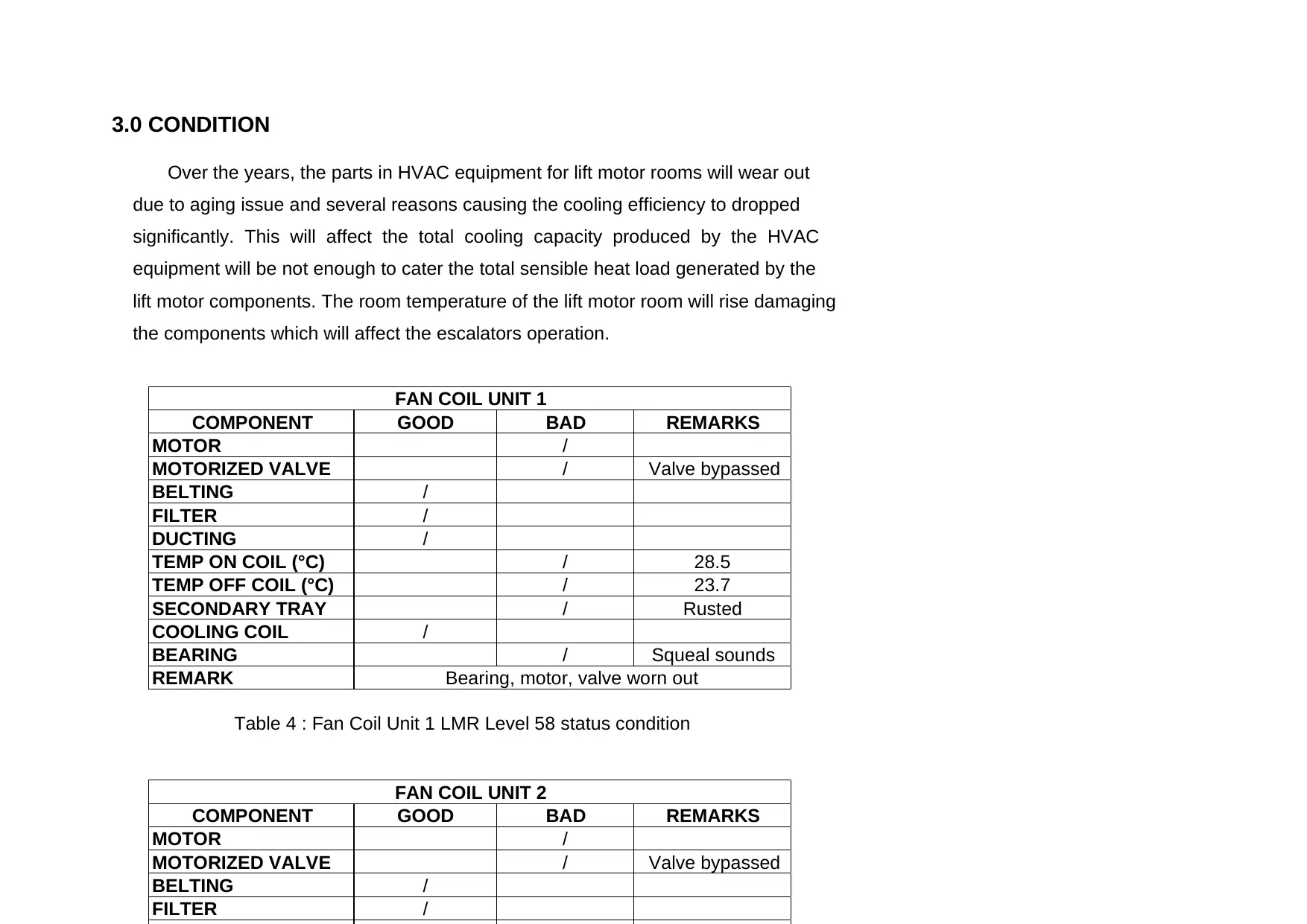
3.0 CONDITION
Over the years, the parts in HVAC equipment for lift motor rooms will wear out
due to aging issue and several reasons causing the cooling efficiency to dropped
significantly. This will affect the total cooling capacity produced by the HVAC
equipment will be not enough to cater the total sensible heat load generated by the
lift motor components. The room temperature of the lift motor room will rise damaging
the components which will affect the escalators operation.
Table 4 : Fan Coil Unit 1 LMR Level 58 status condition
COMPONENT GOOD BAD REMARKS
MOTOR /
MOTORIZED VALVE / Valve bypassed
BELTING /
FILTER /
DUCTING /
TEMP ON COIL (°C) / 28.5
TEMP OFF COIL (°C) / 23.7
SECONDARY TRAY / Rusted
COOLING COIL /
BEARING / Squeal sounds
REMARK
FAN COIL UNIT 1
Bearing, motor, valve worn out
COMPONENT GOOD BAD REMARKS
MOTOR /
MOTORIZED VALVE / Valve bypassed
BELTING /
FILTER /
FAN COIL UNIT 2
Paraphrase This Document
Need a fresh take? Get an instant paraphrase of this document with our AI Paraphraser
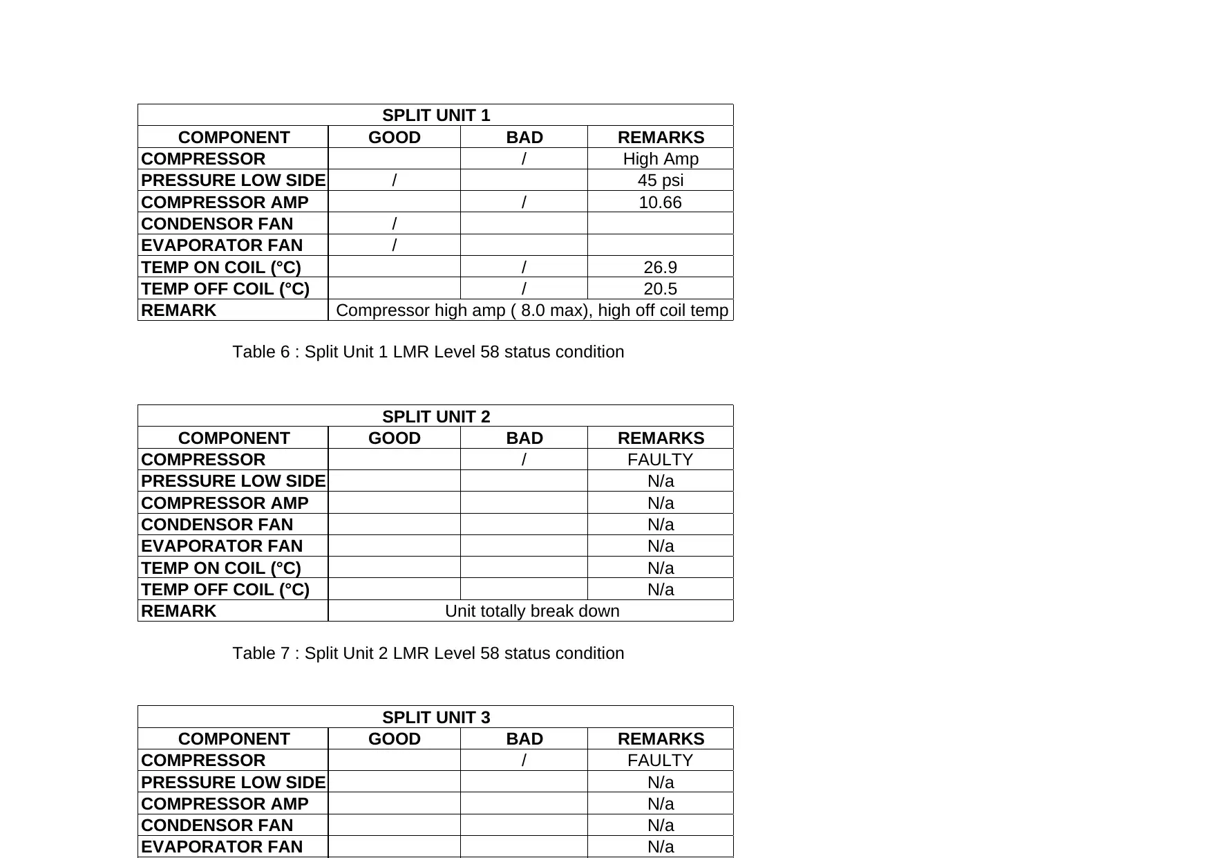
Table 6 : Split Unit 1 LMR Level 58 status condition
Table 7 : Split Unit 2 LMR Level 58 status condition
COMPONENT GOOD BAD REMARKS
COMPRESSOR / High Amp
PRESSURE LOW SIDE / 45 psi
COMPRESSOR AMP / 10.66
CONDENSOR FAN /
EVAPORATOR FAN /
TEMP ON COIL (°C) / 26.9
TEMP OFF COIL (°C) / 20.5
REMARK Compressor high amp ( 8.0 max), high off coil temp
SPLIT UNIT 1
COMPONENT GOOD BAD REMARKS
COMPRESSOR / FAULTY
PRESSURE LOW SIDE N/a
COMPRESSOR AMP N/a
CONDENSOR FAN N/a
EVAPORATOR FAN N/a
TEMP ON COIL (°C) N/a
TEMP OFF COIL (°C) N/a
REMARK Unit totally break down
SPLIT UNIT 2
COMPONENT GOOD BAD REMARKS
COMPRESSOR / FAULTY
PRESSURE LOW SIDE N/a
COMPRESSOR AMP N/a
CONDENSOR FAN N/a
EVAPORATOR FAN N/a
SPLIT UNIT 3
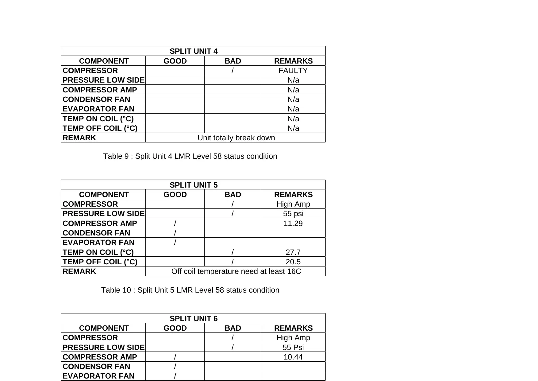
Table 9 : Split Unit 4 LMR Level 58 status condition
Table 10 : Split Unit 5 LMR Level 58 status condition
COMPONENT GOOD BAD REMARKS
COMPRESSOR / FAULTY
PRESSURE LOW SIDE N/a
COMPRESSOR AMP N/a
CONDENSOR FAN N/a
EVAPORATOR FAN N/a
TEMP ON COIL (°C) N/a
TEMP OFF COIL (°C) N/a
REMARK
SPLIT UNIT 4
Unit totally break down
COMPONENT GOOD BAD REMARKS
COMPRESSOR / High Amp
PRESSURE LOW SIDE / 55 psi
COMPRESSOR AMP / 11.29
CONDENSOR FAN /
EVAPORATOR FAN /
TEMP ON COIL (°C) / 27.7
TEMP OFF COIL (°C) / 20.5
REMARK
SPLIT UNIT 5
Off coil temperature need at least 16C
COMPONENT GOOD BAD REMARKS
COMPRESSOR / High Amp
PRESSURE LOW SIDE / 55 Psi
COMPRESSOR AMP / 10.44
CONDENSOR FAN /
EVAPORATOR FAN /
SPLIT UNIT 6
⊘ This is a preview!⊘
Do you want full access?
Subscribe today to unlock all pages.
Trusted by 1+ million students worldwide
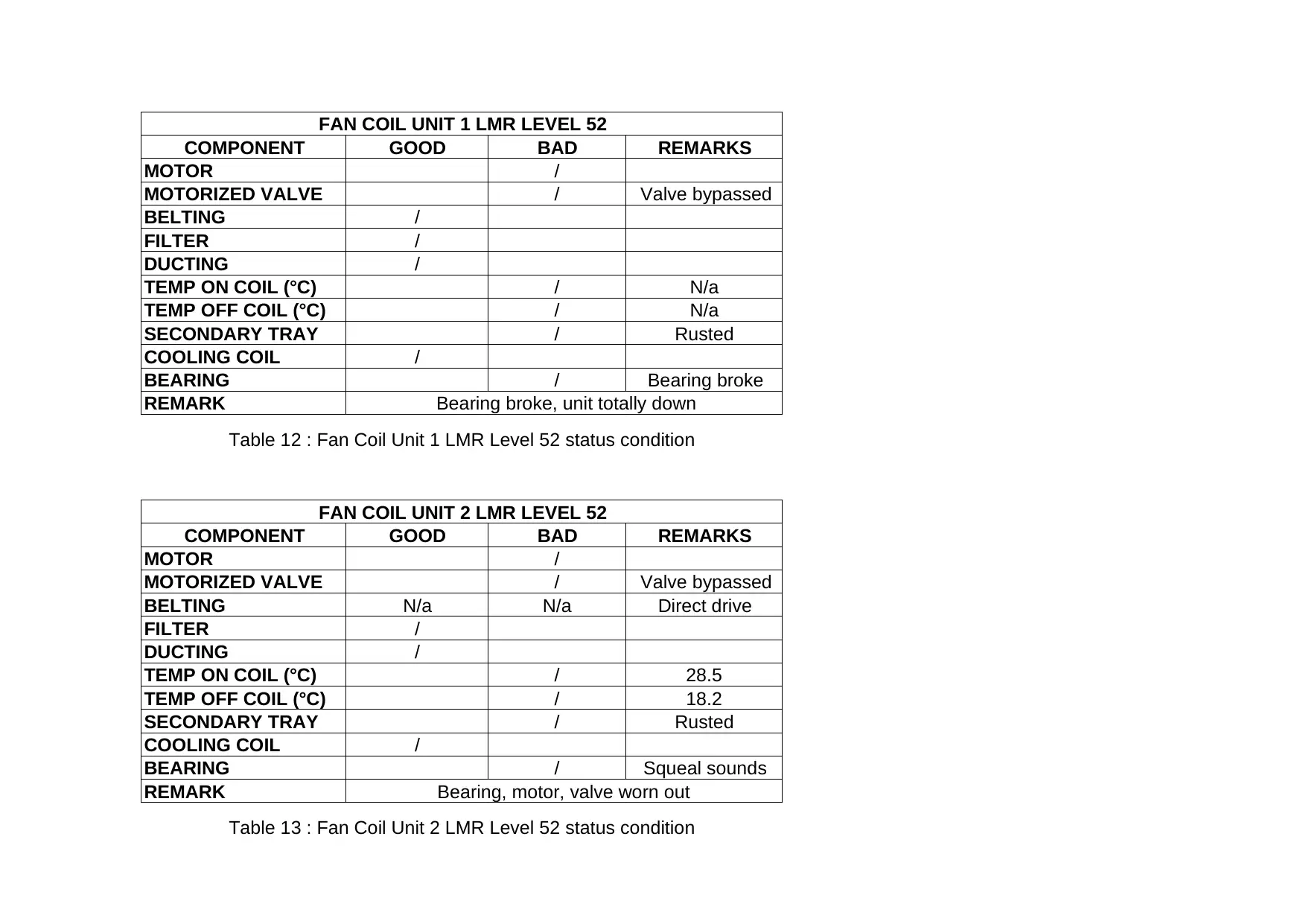
Table 12 : Fan Coil Unit 1 LMR Level 52 status condition
Table 13 : Fan Coil Unit 2 LMR Level 52 status condition
COMPONENT GOOD BAD REMARKS
MOTOR /
MOTORIZED VALVE / Valve bypassed
BELTING /
FILTER /
DUCTING /
TEMP ON COIL (°C) / N/a
TEMP OFF COIL (°C) / N/a
SECONDARY TRAY / Rusted
COOLING COIL /
BEARING / Bearing broke
REMARK
FAN COIL UNIT 1 LMR LEVEL 52
Bearing broke, unit totally down
COMPONENT GOOD BAD REMARKS
MOTOR /
MOTORIZED VALVE / Valve bypassed
BELTING N/a N/a Direct drive
FILTER /
DUCTING /
TEMP ON COIL (°C) / 28.5
TEMP OFF COIL (°C) / 18.2
SECONDARY TRAY / Rusted
COOLING COIL /
BEARING / Squeal sounds
REMARK
FAN COIL UNIT 2 LMR LEVEL 52
Bearing, motor, valve worn out
Paraphrase This Document
Need a fresh take? Get an instant paraphrase of this document with our AI Paraphraser
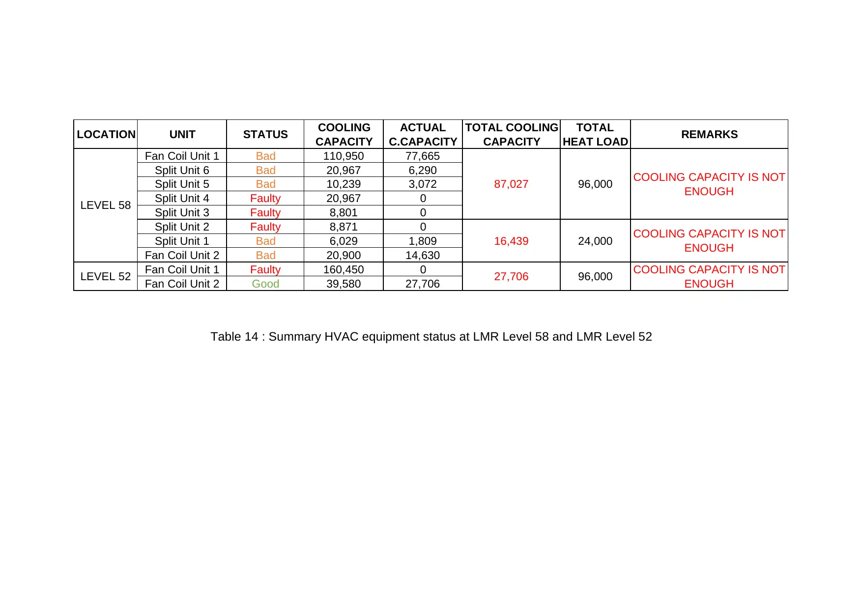
Table 14 : Summary HVAC equipment status at LMR Level 58 and LMR Level 52
LOCATION UNIT STATUS COOLING
CAPACITY
ACTUAL
C.CAPACITY
TOTAL COOLING
CAPACITY
TOTAL
HEAT LOAD REMARKS
Fan Coil Unit 1 Bad 110,950 77,665
Split Unit 6 Bad 20,967 6,290
Split Unit 5 Bad 10,239 3,072
Split Unit 4 Faulty 20,967 0
Split Unit 3 Faulty 8,801 0
Split Unit 2 Faulty 8,871 0
Split Unit 1 Bad 6,029 1,809
Fan Coil Unit 2 Bad 20,900 14,630
Fan Coil Unit 1 Faulty 160,450 0
Fan Coil Unit 2 Good 39,580 27,706
96,000
24,000
96,000
COOLING CAPACITY IS NOT
ENOUGH
COOLING CAPACITY IS NOT
ENOUGH
COOLING CAPACITY IS NOT
ENOUGH
LEVEL 58
LEVEL 52 27,706
16,439
87,027
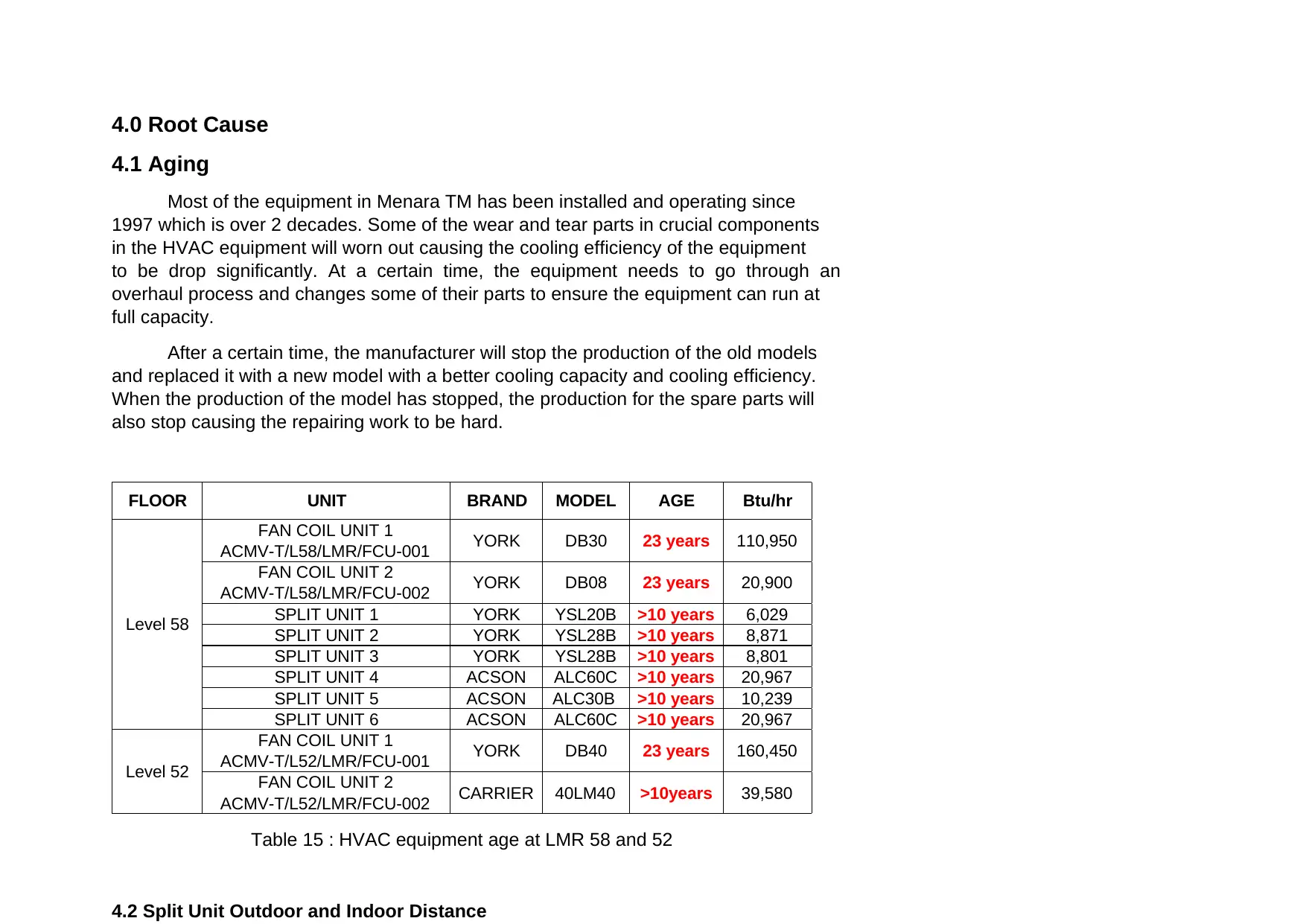
4.0 Root Cause
4.1 Aging
Most of the equipment in Menara TM has been installed and operating since
1997 which is over 2 decades. Some of the wear and tear parts in crucial components
in the HVAC equipment will worn out causing the cooling efficiency of the equipment
to be drop significantly. At a certain time, the equipment needs to go through an
overhaul process and changes some of their parts to ensure the equipment can run at
full capacity.
After a certain time, the manufacturer will stop the production of the old models
and replaced it with a new model with a better cooling capacity and cooling efficiency.
When the production of the model has stopped, the production for the spare parts will
also stop causing the repairing work to be hard.
Table 15 : HVAC equipment age at LMR 58 and 52
4.2 Split Unit Outdoor and Indoor Distance
FLOOR UNIT BRAND MODEL AGE Btu/hr
FAN COIL UNIT 1
ACMV-T/L58/LMR/FCU-001 YORK DB30 23 years 110,950
FAN COIL UNIT 2
ACMV-T/L58/LMR/FCU-002 YORK DB08 23 years 20,900
SPLIT UNIT 1 YORK YSL20B >10 years 6,029
SPLIT UNIT 2 YORK YSL28B >10 years 8,871
SPLIT UNIT 3 YORK YSL28B >10 years 8,801
SPLIT UNIT 4 ACSON ALC60C >10 years 20,967
SPLIT UNIT 5 ACSON ALC30B >10 years 10,239
SPLIT UNIT 6 ACSON ALC60C >10 years 20,967
FAN COIL UNIT 1
ACMV-T/L52/LMR/FCU-001 YORK DB40 23 years 160,450
FAN COIL UNIT 2
ACMV-T/L52/LMR/FCU-002 CARRIER 40LM40 >10years 39,580
Level 58
Level 52
⊘ This is a preview!⊘
Do you want full access?
Subscribe today to unlock all pages.
Trusted by 1+ million students worldwide
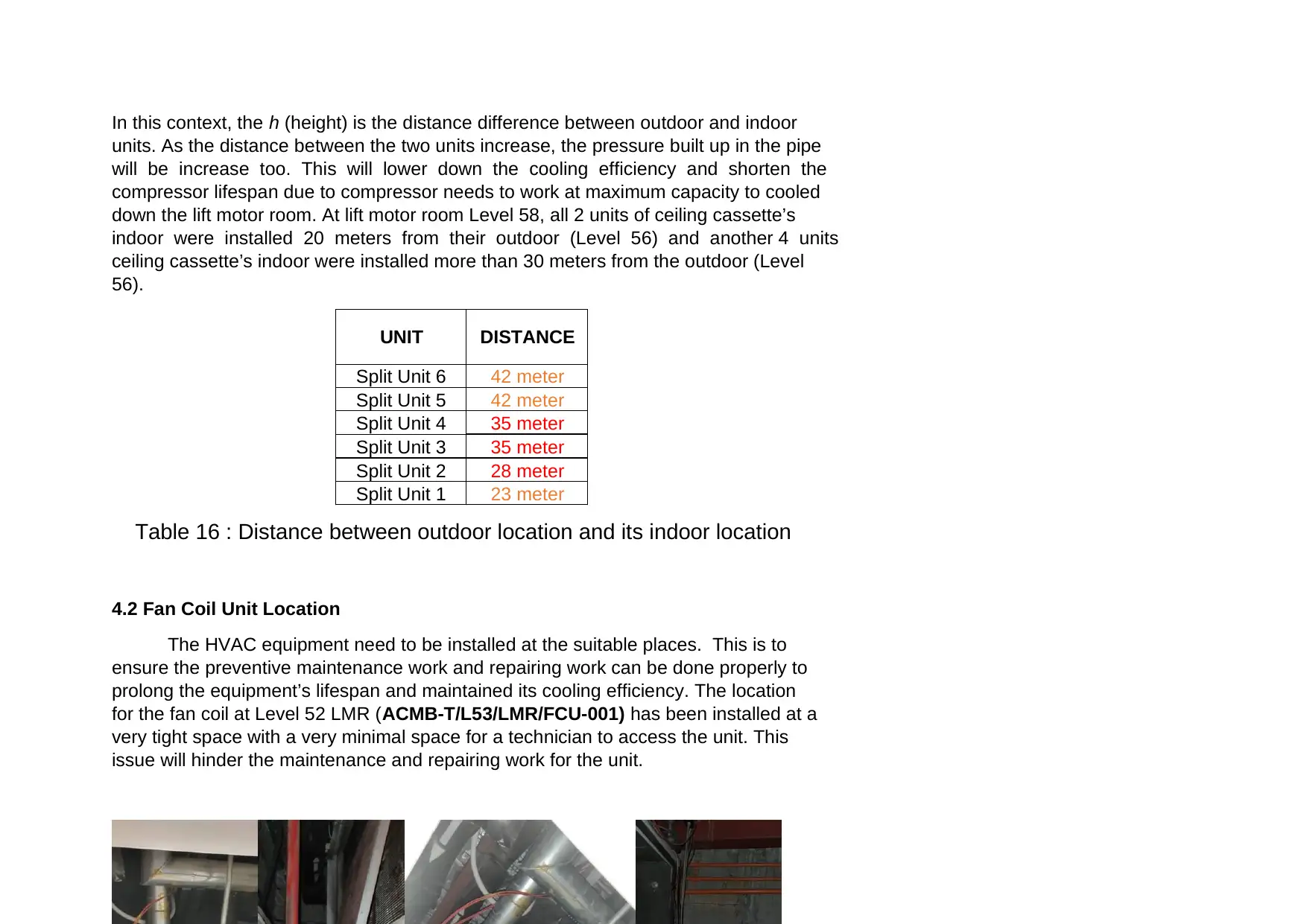
In this context, the h (height) is the distance difference between outdoor and indoor
units. As the distance between the two units increase, the pressure built up in the pipe
will be increase too. This will lower down the cooling efficiency and shorten the
compressor lifespan due to compressor needs to work at maximum capacity to cooled
down the lift motor room. At lift motor room Level 58, all 2 units of ceiling cassette’s
indoor were installed 20 meters from their outdoor (Level 56) and another 4 units
ceiling cassette’s indoor were installed more than 30 meters from the outdoor (Level
56).
Table 16 : Distance between outdoor location and its indoor location
4.2 Fan Coil Unit Location
The HVAC equipment need to be installed at the suitable places. This is to
ensure the preventive maintenance work and repairing work can be done properly to
prolong the equipment’s lifespan and maintained its cooling efficiency. The location
for the fan coil at Level 52 LMR (ACMB-T/L53/LMR/FCU-001) has been installed at a
very tight space with a very minimal space for a technician to access the unit. This
issue will hinder the maintenance and repairing work for the unit.
UNIT DISTANCE
Split Unit 6 42 meter
Split Unit 5 42 meter
Split Unit 4 35 meter
Split Unit 3 35 meter
Split Unit 2 28 meter
Split Unit 1 23 meter
Paraphrase This Document
Need a fresh take? Get an instant paraphrase of this document with our AI Paraphraser
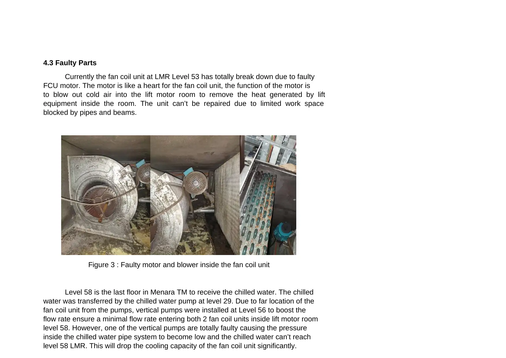
4.3 Faulty Parts
Currently the fan coil unit at LMR Level 53 has totally break down due to faulty
FCU motor. The motor is like a heart for the fan coil unit, the function of the motor is
to blow out cold air into the lift motor room to remove the heat generated by lift
equipment inside the room. The unit can’t be repaired due to limited work space
blocked by pipes and beams.
Figure 3 : Faulty motor and blower inside the fan coil unit
Level 58 is the last floor in Menara TM to receive the chilled water. The chilled
water was transferred by the chilled water pump at level 29. Due to far location of the
fan coil unit from the pumps, vertical pumps were installed at Level 56 to boost the
flow rate ensure a minimal flow rate entering both 2 fan coil units inside lift motor room
level 58. However, one of the vertical pumps are totally faulty causing the pressure
inside the chilled water pipe system to become low and the chilled water can’t reach
level 58 LMR. This will drop the cooling capacity of the fan coil unit significantly.
5.0 PROPOSED SOLUTION
5.1 LEVEL 58 LIFT MOTOR ROOM
OPTION 1 – NEW AIR-CONDITIONING SYSTEM & REPAIR VERTICAL PUMP
The existing split unit at level 58 LMR was poorly design and very old. The
distance between the outdoor and indoor is exceeding the ideal distance limits of 15
meters with a distance of above 25 meters. This will shorten the lifespan of the units
due to compressor needs to operate at a maximum capacity to cool down the lift motor
room to the desire temperature.
By installing Variable Refrigerant Frequency (VRF) the distance between
outdoor and indoor location can be solved. A VRF system can has a greater distance
limit between its indoor and outdoor with around 45 meters. With a further distance
limit, the cooling capacity and the cooling efficiency will not be affected as happened
to the conventional split unit.
The faulty vertical pump at Level 56 need to be replaced in other to ensure the
pressure inside the chilled water system is enough to supplied enough flow rate to fan
coil unit at level 58 lift motor room.
OPTION 2 – REPAIR/REPLACE THE EXISTING CONVENTIONAL SPLIT UNIT &
REPAIR VERTICAL PUMP
The cheaper option is to repair or replace the existing conventional split unit.
However, the issue will expect to happen again in the nearest future due to poor
design of the split unit installation. The distance between indoor and outdoor
exceeding the ideal limits will void the warranty and shorten the lifespan of the units.
⊘ This is a preview!⊘
Do you want full access?
Subscribe today to unlock all pages.
Trusted by 1+ million students worldwide
1 out of 15
Your All-in-One AI-Powered Toolkit for Academic Success.
+13062052269
info@desklib.com
Available 24*7 on WhatsApp / Email
![[object Object]](/_next/static/media/star-bottom.7253800d.svg)
Unlock your academic potential
Copyright © 2020–2026 A2Z Services. All Rights Reserved. Developed and managed by ZUCOL.