MEC 301: Manufacturing Processes of an Air Engine - A Detailed Report
VerifiedAdded on 2023/06/12
|10
|1595
|238
Report
AI Summary
This report details the process of machining a basic air engine, covering the identification of needs, background research, goal statement, task specifications, and process description. It includes the selection and implementation of manufacturing processes, parameter selection, process analysis, and production and cost analysis. The report also presents results, discussion, summary, conclusions, acknowledgments, and references. The project involved modeling and simulating the manufacturing procedure using Autodesk Inventor, with a focus on machining the engine components and verifying their functionality. The final product was tested using a compressed air source, demonstrating smooth movement of the engine parts.
Running head: MANUFACTURING PROCESSES
MANUFACTURING PROCESSES
[Author Name(s), First M. Last, Omit Titles and Degrees]
[Institutional Affiliation(s)]
MANUFACTURING PROCESSES
[Author Name(s), First M. Last, Omit Titles and Degrees]
[Institutional Affiliation(s)]
Paraphrase This Document
Need a fresh take? Get an instant paraphrase of this document with our AI Paraphraser
2
MANUFACTURING PROCESSES
Abstract
In the modern days, several attempts have been made by engineers to make improvements on
the existing engines. An air engine just like the steam engine uses compressed air but it is an
emission free. This compressed air is used is used to perform the work against the piston. The
components of such engines are made through machining using relevant tools. The
machining process takes into account the standard requirement of the existing ones.
Introduction
The project main objective was to build air engine. This helped in determining what was
possible to machine and what was not possible. Building an air engine that is also called an
oscillating engine was so simple. The process proceeded as follows,
Identification of the needs
The process required the following materials:
4” length of 3/8” square cold roll steel bar,1.5length of diameter 3/8” CRS rod.,19”-32 UNF
nut,2.8” length of diameter 1875 Drill rod,1.1” length of diamete25” Drill rod, Diameter 125
by 38” Dowel pin,2” length of diameter 63” CRS rod,15/8” by 15/8” piece of 25” thick
aluminium plate, A small coil spring,5/8” length of diameter 1 rod,19”-32 by .5” FHS counter
sunk screw and 138”-32 by 2.5” set screw.
.
A counter sunk screw
3
MANUFACTURING PROCESSES
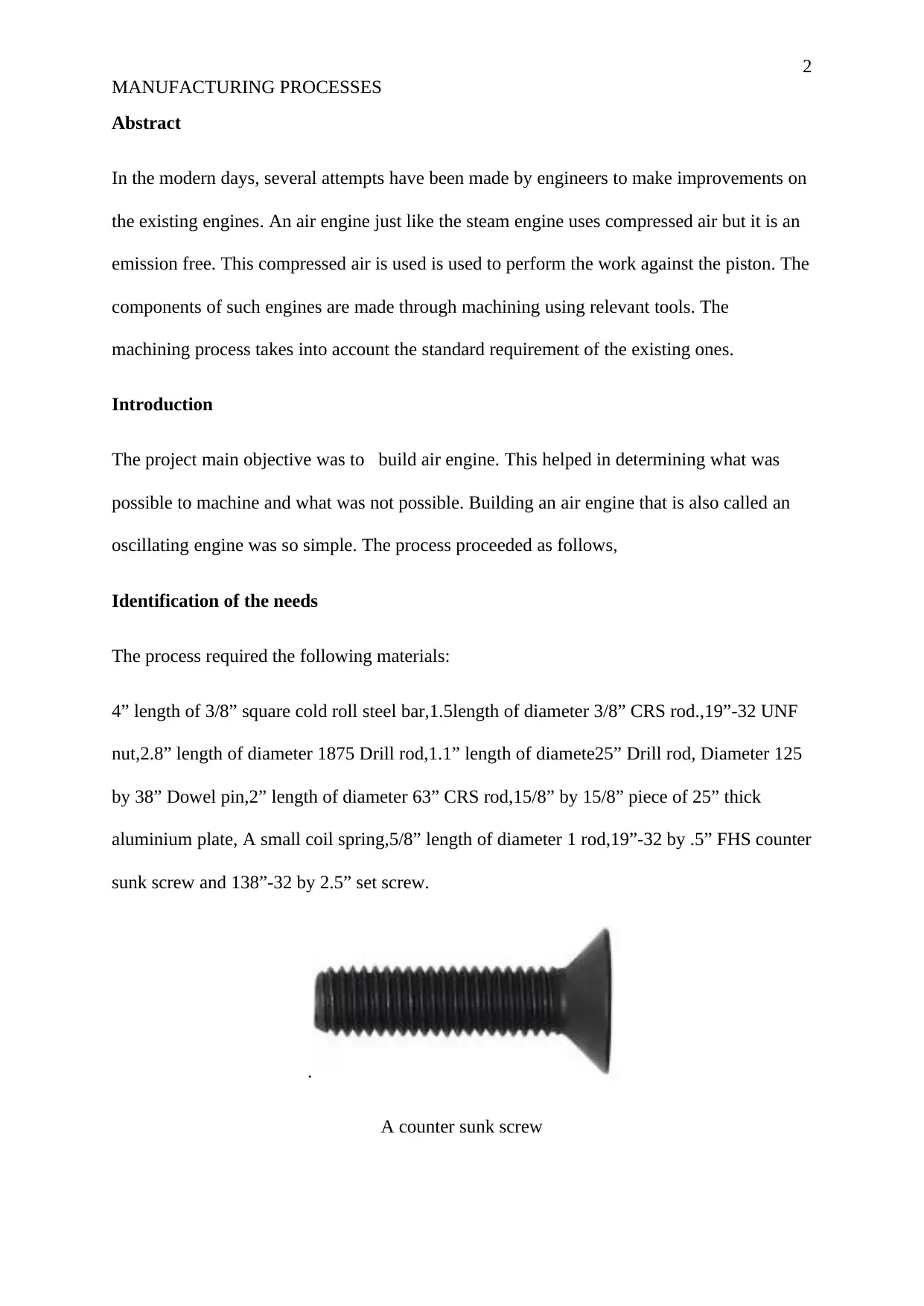
A UNF nut Dowel pins drill rod
Edge finder
The tools needed for the process included the following
A milling machine, metal lathe, grinder, a band saw, a file, an arbour press, edge finder, a
parting tool, calipers,3/8” by3” lathe tool bits,10-32,6-32 taps and file, reamers of diameters
1240”,1260”1855” and 2510” and finally a set of drills from1/16”-1/4” indexed by1/64”.
MANUFACTURING PROCESSES
A UNF nut Dowel pins drill rod
Edge finder
The tools needed for the process included the following
A milling machine, metal lathe, grinder, a band saw, a file, an arbour press, edge finder, a
parting tool, calipers,3/8” by3” lathe tool bits,10-32,6-32 taps and file, reamers of diameters
1240”,1260”1855” and 2510” and finally a set of drills from1/16”-1/4” indexed by1/64”.
⊘ This is a preview!⊘
Do you want full access?
Subscribe today to unlock all pages.
Trusted by 1+ million students worldwide
4
MANUFACTURING PROCESSES
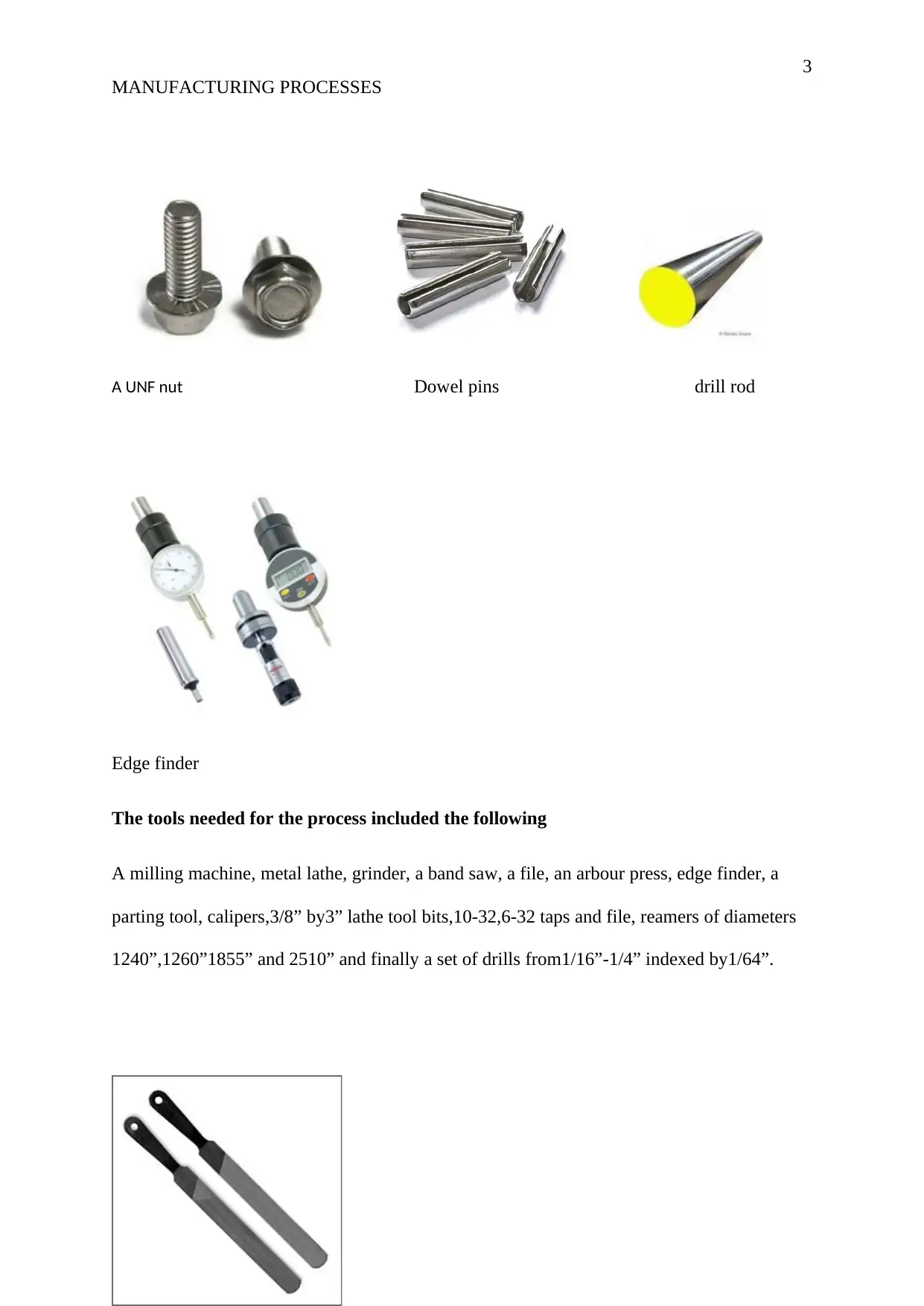
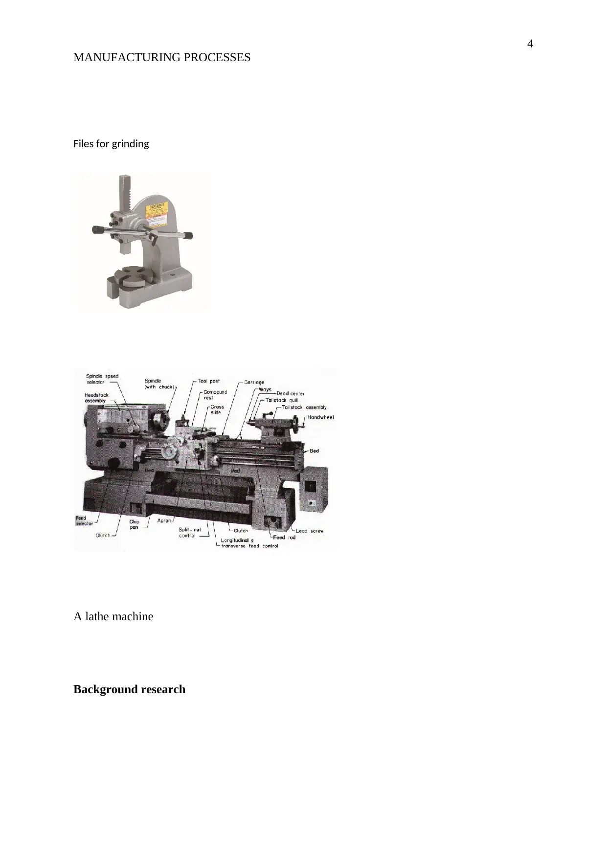
Files for grinding
A lathe machine
Background research
MANUFACTURING PROCESSES
Files for grinding
A lathe machine
Background research
Paraphrase This Document
Need a fresh take? Get an instant paraphrase of this document with our AI Paraphraser
5
MANUFACTURING PROCESSES
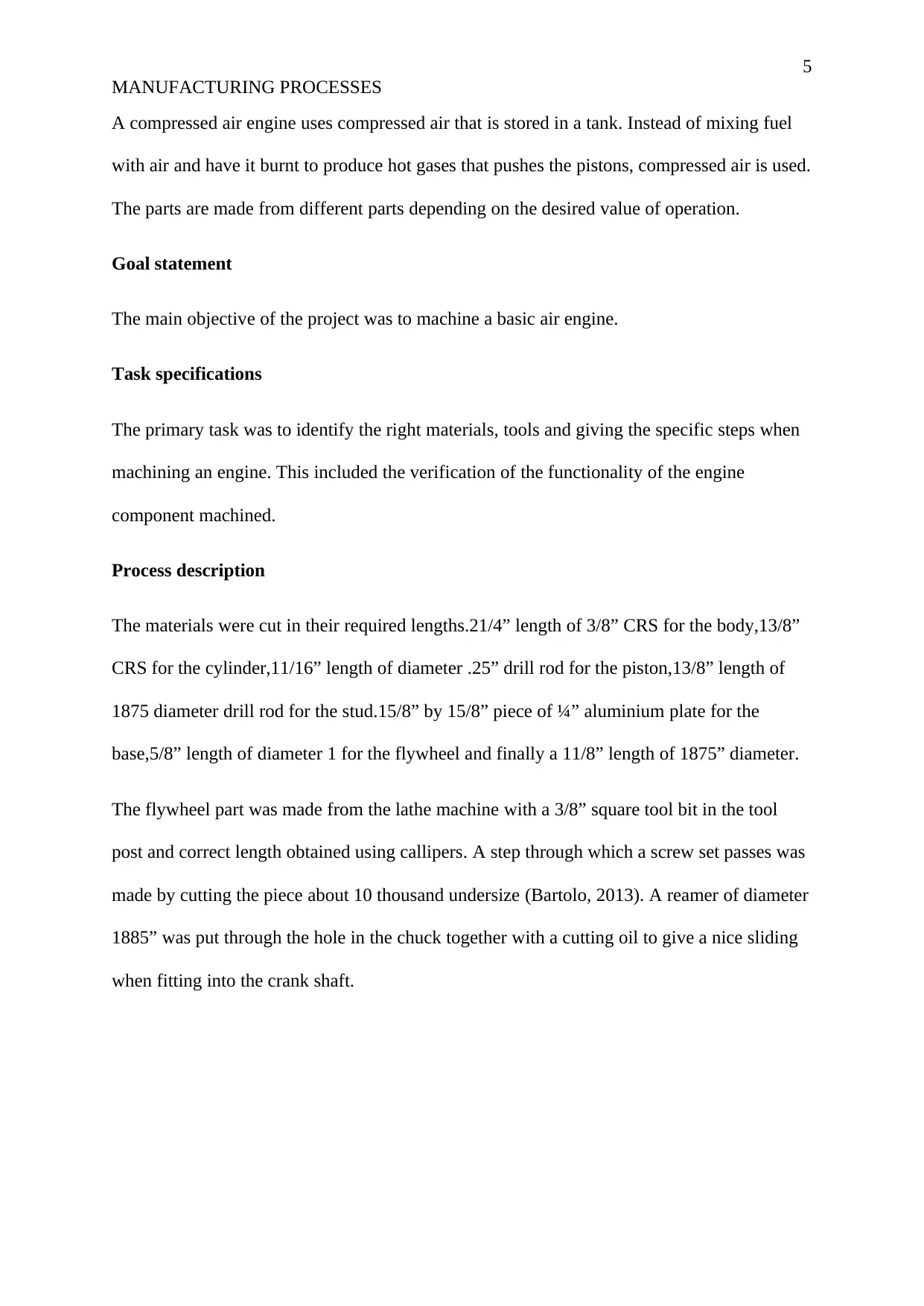
A compressed air engine uses compressed air that is stored in a tank. Instead of mixing fuel
with air and have it burnt to produce hot gases that pushes the pistons, compressed air is used.
The parts are made from different parts depending on the desired value of operation.
Goal statement
The main objective of the project was to machine a basic air engine.
Task specifications
The primary task was to identify the right materials, tools and giving the specific steps when
machining an engine. This included the verification of the functionality of the engine
component machined.
Process description
The materials were cut in their required lengths.21/4” length of 3/8” CRS for the body,13/8”
CRS for the cylinder,11/16” length of diameter .25” drill rod for the piston,13/8” length of
1875 diameter drill rod for the stud.15/8” by 15/8” piece of ¼” aluminium plate for the
base,5/8” length of diameter 1 for the flywheel and finally a 11/8” length of 1875” diameter.
The flywheel part was made from the lathe machine with a 3/8” square tool bit in the tool
post and correct length obtained using callipers. A step through which a screw set passes was
made by cutting the piece about 10 thousand undersize (Bartolo, 2013). A reamer of diameter
1885” was put through the hole in the chuck together with a cutting oil to give a nice sliding
when fitting into the crank shaft.
MANUFACTURING PROCESSES
A compressed air engine uses compressed air that is stored in a tank. Instead of mixing fuel
with air and have it burnt to produce hot gases that pushes the pistons, compressed air is used.
The parts are made from different parts depending on the desired value of operation.
Goal statement
The main objective of the project was to machine a basic air engine.
Task specifications
The primary task was to identify the right materials, tools and giving the specific steps when
machining an engine. This included the verification of the functionality of the engine
component machined.
Process description
The materials were cut in their required lengths.21/4” length of 3/8” CRS for the body,13/8”
CRS for the cylinder,11/16” length of diameter .25” drill rod for the piston,13/8” length of
1875 diameter drill rod for the stud.15/8” by 15/8” piece of ¼” aluminium plate for the
base,5/8” length of diameter 1 for the flywheel and finally a 11/8” length of 1875” diameter.
The flywheel part was made from the lathe machine with a 3/8” square tool bit in the tool
post and correct length obtained using callipers. A step through which a screw set passes was
made by cutting the piece about 10 thousand undersize (Bartolo, 2013). A reamer of diameter
1885” was put through the hole in the chuck together with a cutting oil to give a nice sliding
when fitting into the crank shaft.
6
MANUFACTURING PROCESSES
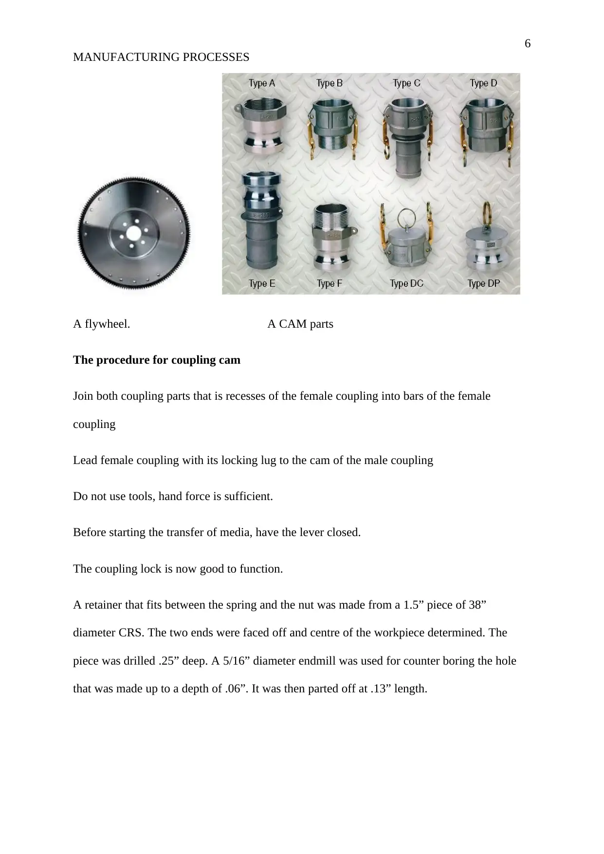
A flywheel. A CAM parts
The procedure for coupling cam
Join both coupling parts that is recesses of the female coupling into bars of the female
coupling
Lead female coupling with its locking lug to the cam of the male coupling
Do not use tools, hand force is sufficient.
Before starting the transfer of media, have the lever closed.
The coupling lock is now good to function.
A retainer that fits between the spring and the nut was made from a 1.5” piece of 38”
diameter CRS. The two ends were faced off and centre of the workpiece determined. The
piece was drilled .25” deep. A 5/16” diameter endmill was used for counter boring the hole
that was made up to a depth of .06”. It was then parted off at .13” length.
MANUFACTURING PROCESSES
A flywheel. A CAM parts
The procedure for coupling cam
Join both coupling parts that is recesses of the female coupling into bars of the female
coupling
Lead female coupling with its locking lug to the cam of the male coupling
Do not use tools, hand force is sufficient.
Before starting the transfer of media, have the lever closed.
The coupling lock is now good to function.
A retainer that fits between the spring and the nut was made from a 1.5” piece of 38”
diameter CRS. The two ends were faced off and centre of the workpiece determined. The
piece was drilled .25” deep. A 5/16” diameter endmill was used for counter boring the hole
that was made up to a depth of .06”. It was then parted off at .13” length.
⊘ This is a preview!⊘
Do you want full access?
Subscribe today to unlock all pages.
Trusted by 1+ million students worldwide
7
MANUFACTURING PROCESSES
The crank was made by mounting a 2” piece of diameter 63” in the three-jaw chuck. The
ends were faced off to make them square. The centre was identified and .25” deep hole was
dug using a #16 drill. The piece was the parted off .15” wide.
To make the piston a work piece of 11/16” length of 25 diameter drill rod was used. The ends
were faced off and later chamfered on the outside edge.11/8” length of diameter 1875” was
faced off on both ends and chamfered. A 13/8” length of diameter 1875 was used as a stud
after being faced to a length of 1.25”. The stud was threaded so that it could screw into the
body.
The base from 15/8” by 15/8” by ¼” aluminium plate. The square piece was milled with two
end parallel to each other. The hole was then dug at the centre. A work piece for piston was
the measured and .813” subtracted from it. The X and Y dimensions were determined with X
being 0.75” and Y ¼” and a 0.25” deep cut per pass. A drill of #32 was passed through to
achieve the hole to 1260” diameter.
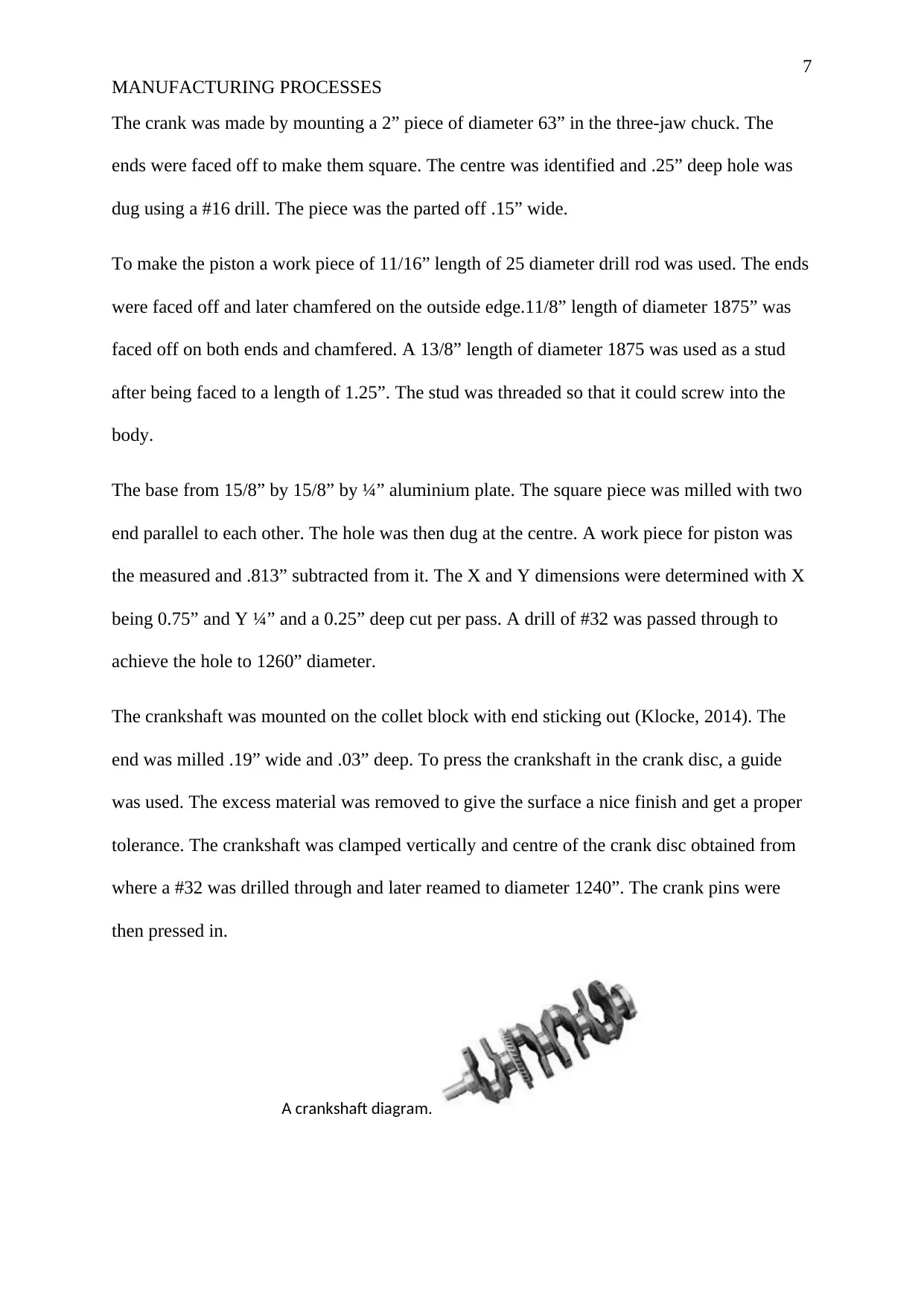
The crankshaft was mounted on the collet block with end sticking out (Klocke, 2014). The
end was milled .19” wide and .03” deep. To press the crankshaft in the crank disc, a guide
was used. The excess material was removed to give the surface a nice finish and get a proper
tolerance. The crankshaft was clamped vertically and centre of the crank disc obtained from
where a #32 was drilled through and later reamed to diameter 1240”. The crank pins were
then pressed in.
A crankshaft diagram.
MANUFACTURING PROCESSES
The crank was made by mounting a 2” piece of diameter 63” in the three-jaw chuck. The
ends were faced off to make them square. The centre was identified and .25” deep hole was
dug using a #16 drill. The piece was the parted off .15” wide.
To make the piston a work piece of 11/16” length of 25 diameter drill rod was used. The ends
were faced off and later chamfered on the outside edge.11/8” length of diameter 1875” was
faced off on both ends and chamfered. A 13/8” length of diameter 1875 was used as a stud
after being faced to a length of 1.25”. The stud was threaded so that it could screw into the
body.
The base from 15/8” by 15/8” by ¼” aluminium plate. The square piece was milled with two
end parallel to each other. The hole was then dug at the centre. A work piece for piston was
the measured and .813” subtracted from it. The X and Y dimensions were determined with X
being 0.75” and Y ¼” and a 0.25” deep cut per pass. A drill of #32 was passed through to
achieve the hole to 1260” diameter.
The crankshaft was mounted on the collet block with end sticking out (Klocke, 2014). The
end was milled .19” wide and .03” deep. To press the crankshaft in the crank disc, a guide
was used. The excess material was removed to give the surface a nice finish and get a proper
tolerance. The crankshaft was clamped vertically and centre of the crank disc obtained from
where a #32 was drilled through and later reamed to diameter 1240”. The crank pins were
then pressed in.
A crankshaft diagram.
Paraphrase This Document
Need a fresh take? Get an instant paraphrase of this document with our AI Paraphraser
8
MANUFACTURING PROCESSES
The hole in the flywheel was then drilled and tapped. The drill chuck was turned so that the
tap threaded itself. The workpiece was then disengaged from the chuck and the flywheel was
done. To make the cylinder, the workpiece was mounted in the mill vice with ¼” protruding
from the top of the vice. The centre was located and a hole of 15/64” by .72” deep obtained.
The hole was then reamed to diameter of .2510”. A hole of #16 was drilled was drilled .938”
off the edge and reamed to 1885.” Another hole 1/16” was drilled through one wall that
connects to diameter 2510” hole. On the same lower part, a hole of .03” by .56” was undercut
(Klocke, 2014).
The body was then made clamping the workpiece horizontally. A #16 was cut through hand
then reamed with oil ream of diameter of 1885.” A drill of #21 by .34” deep was obtained
above 10-32 hole of the stud. All the relevant holes with attachments were made with unique
specifications for the attachments of other components.
Production and cost analysis
The cost of the materials parts became the basis of determining the expenses incurred. Labour
was also factored in. It was out that it is much cheaper to machine an engine. The elimination
of transport and middle men made the production cheaper.
The specific parts that were considered secondary during the project were cheaply acquired.
However, in terms of the efficiency, it was found out that the commercial ones were more
efficient with perfect surface finish
The errors that were present during the production must have escalated the cost of production
9
MANUFACTURING PROCESSES
Results and discussion
When the parts were assembled, the final product was subjected to test. A source of air was
used to power the engine. The flywheel was given a little flick after connecting the air source.
The engine parts moved smoothly and I could be compared to the available engines in the
market.
Summary and conclusion
It was interesting machining the engine. A lot of concentration was required especially when
precious values were to be taken during measurements. This made the process somehow
tiresome.
Acknowledgment
May I express my sincere thanks of gratitude to my teacher who guided us through this
project.
⊘ This is a preview!⊘
Do you want full access?
Subscribe today to unlock all pages.
Trusted by 1+ million students worldwide

10
MANUFACTURING PROCESSES
References
Bartolo, H. (2013). Green Design, Materials and Manufacturing Processes. Moscow: CRC
Press.
Klocke, F. (2014). Manufacturing Processes 4: Forming. New York: Springer Science &
Business Media.
MANUFACTURING PROCESSES
References
Bartolo, H. (2013). Green Design, Materials and Manufacturing Processes. Moscow: CRC
Press.
Klocke, F. (2014). Manufacturing Processes 4: Forming. New York: Springer Science &
Business Media.
1 out of 10
Your All-in-One AI-Powered Toolkit for Academic Success.
+13062052269
info@desklib.com
Available 24*7 on WhatsApp / Email
![[object Object]](/_next/static/media/star-bottom.7253800d.svg)
Unlock your academic potential
Copyright © 2020–2026 A2Z Services. All Rights Reserved. Developed and managed by ZUCOL.