Analysis of Gas Turbine Engine Combustion Systems on Aircraft
VerifiedAdded on 2020/03/16
|18
|4656
|181
Report
AI Summary
This report provides a comprehensive analysis of gas turbine engine combustion systems used in aircraft. It begins with an introduction to the fundamental principles of combustion within gas turbine engines, emphasizing the importance of efficient fuel-air mixing and controlled combustion. The report then delves into the development of gas turbine engine combustion systems, tracing the evolution from early designs to modern configurations. A detailed examination of the working mechanisms of combustion systems follows, explaining the processes of air compression, fuel injection, and ignition. The core of the report focuses on comparing three primary types of combustion systems: the can, can-annular, and annular combustors. Each type is described in detail, highlighting its design, advantages, and disadvantages. The report also explores various cooling airflow arrangements used to protect combustion systems from extreme temperatures, ensuring the longevity and efficiency of the engine. Finally, the report concludes by summarizing the key findings and emphasizing the importance of ongoing research and development in this critical area of aerospace engineering.
Running head: GAS TURBINE ENGINE COMBUSTION SYSTEMS
Gas Turbine Engine Combustion Systems on Aircraft
Name of the student:
Name of the university:
Author Note
Gas Turbine Engine Combustion Systems on Aircraft
Name of the student:
Name of the university:
Author Note
Paraphrase This Document
Need a fresh take? Get an instant paraphrase of this document with our AI Paraphraser
1GAS TURBINE ENGINE COMBUSTION SYSTEMS
1. Summary
The report is developed to analyze and examine the developing of the gas turbine engine combustion
in aircrafts. It demonstrates the working mechanisms of the combustion system. This also includes
its descriptions. The three common types of combustion systems are compared. At last it considers
the other cooling arrangements of airflow that are also used for the cooling combustion system.
2GAS TURBINE ENGINE COMBUSTION SYSTEMS
Table of Contents
2. Introduction:......................................................................................................................................3
3. Investigating and describing the developing of the gas turbine engine combustion systems:..........3
4. The working mechanism of combustion system:..............................................................................4
5. The 'Can' combustion system:...........................................................................................................5
6. The 'Can-Annular' combustion system:.............................................................................................6
7. 'Annular' combustion system:............................................................................................................7
8. A brief comparison of the three combustion systems:.......................................................................8
9. Other cooling airflow arrangements used to cool combustion systems:.........................................11
10. Conclusion:....................................................................................................................................13
11. References:....................................................................................................................................14
⊘ This is a preview!⊘
Do you want full access?
Subscribe today to unlock all pages.
Trusted by 1+ million students worldwide
3GAS TURBINE ENGINE COMBUSTION SYSTEMS
2. Introduction:
The gas turbine engine combustion system on the aircraft houses the process of combustion.
It raises the temperature of the air by passing through the engine. The main function of the section is
to burn the air or fuel mixture adding heat energy to the air.
In order to do all this, the combustion chamber is meant to deliver the ways of proper mixing
of the air and fuel, assuring a good combustion. They must burn the mixture carefully. Then the hot
combustion products must be cooled to the temperature that the inlet of the turbine guides the blades
or vanes within the operating conditions. Lastly, it delivers the hot gases towards the turbine part.
There are three fundamental kinds of combustion chambers currently. They just vary in terms of
detailing. They are can-combustion, can-annular and annular type.
The following report is prepared to describe and investigate the developing of the gas turbine
engine combustion. It analyses the working mechanisms of the combustion system along with its
descriptions. Then the different kinds of combustion systems are discussed. Then, all these
combustion systems are compared. Lastly, the report discusses the other cooling arrangements of
airflow used for the cooling combustion system.
3. Investigating and describing the developing of the gas turbine engine
combustion systems:
The industrial revolution came to be the reality as the access to the devices of the energy
conversions got dispatched on the demand. For instance, before this innovation, the ships were
moving through sails and so on. The reciprocating design, the original steam engine of Newcomen
was the first breakthrough. After that James Watt added the condenser tripling the efficiency. Then a
Paraphrase This Document
Need a fresh take? Get an instant paraphrase of this document with our AI Paraphraser
4GAS TURBINE ENGINE COMBUSTION SYSTEMS
more popular turbine was developed by Sir Charles Parsons. The size of the first steam turbine was
having a minimal at about 7 kW reaching up to 2000 MW (Ferguson and Kirkpatrick, A.T 2015).
At the same time and totally unrelated was George Brayton’s design of constant pressure
system that evolved into the gas turbine. As the human history powered light, the new internal
combustion engines exploited in the Otto and Brayton cycles. The relation between the aircraft and
auto was too simple to make various large automobile manufacturers possesses the aircraft engine
agencies. In Europe, distinct types of aircraft engines were being explored in Great Britain and
Germany. The design of Von Ohain included the axial compressor, combustor and the axial
expansion turbine looking same to any steam turbine. This established as the milestone for the
powered flight (Wilson and Korakianitis 2014). At the end of 1980’s the previous overbuilding
pressured the uses to scale back the further expansions. An unplanned critical mass reached the
industry by the end of the 20th century. This time, the behavior of the customers also changed
dramatically. The orders came from the conventionally integrated uses, new entrants, merchant
generators, consortiums and independent power producers.
4. The working mechanism of combustion system:
Currently, there have been two types of internal combustion engines in production. They are
the engines of compression ignition diesel and the spark ignition gasoline. Maximum of the four
piston strokes or four-stroke cycle engines are required to complete any cycle. This cycle includes
the four different processes like power and combustion stroke compression, exhaust and intake. In
the spark ignition engine, the fuel gets mixed with the air. It is then inducted in the cylinder while
the intake process takes place. In the diesel engine, the air is just inducted only to the engine. Then it
gets compressed (Şöhret et al. 2016).
5GAS TURBINE ENGINE COMBUSTION SYSTEMS
More precisely in aircraft, the jet engines help in moving the airplane forward. This is done
with the huge force produced by the high thrust causing the plane to fly super fast. Every jet engines
also are known as the gas turbines, has been working on the similar principle. The engines here suck
the air coming from the front with the help of the fan. The compressor increases the air pressure.
This is developed with various blades that are attached to the shaft. Here the blades rotate at large
speed. It squeezes or compresses the air.
Then the air that is compressed is sprayed with the fuel. The mixture of lightened by the
electric spark (Xing et al. 2017). Further, the burning gases stretch and blast out through the nozzle.
This occurs at the back-end of the engine. The jets of the gas shoots at the reverse end, the aircraft
and engine are been thrust in the forward direction. Since the hot air goes to the nozzle, it gets
passed by another set of blades. This is known as the turbine (Rolls Royce 2015). This attached to
the similar shaft as the compressor. The spins of the turbines result in the compressor to rotate.
5. The 'Can' combustion system:
The can combustors are the combustion chambers that are self-contained. They are
cylindrical in shape. Every can possesses their individual fuel injectors, liner, casing, and igniter.
The main air originating from the compressor gets guided to every distinct can. There it gets
decelerated ignited and mixed with fuel. The secondary air has been also originating from the
compressor. There it gets fed outside of the liner. Within this, the combustion has been occurring.
The secondary air then gets fed. This happens generally through the slits within the liner. It happens
into the combustion zone for cooling the linear through the thin film cooling (Kuz'michev et al.
2014).
⊘ This is a preview!⊘
Do you want full access?
Subscribe today to unlock all pages.
Trusted by 1+ million students worldwide
6GAS TURBINE ENGINE COMBUSTION SYSTEMS
The multiple cans, in most applications, have been arranged across the core axis of the
engine. Then the shared exhaust is been fed to the turbine.
These kinds of combustors are broadly used in the previous gas turbine. This has been owing
to the easiness of testing and design (Rolls Royce 2015). For instance, one could test the single can
instead of having to test the entire system. They are easy to maintain. This is because the single
could be eradicated instead of the entire combustion system.
However, maximum of the current gas turbine engines especially for the aircraft applications
never make use of the can combustors (Aydin et al. 2015). This is because they often measure more
in weight than its alternatives. Moreover, the drop in pressure around the can is more than the other
combustors.
The cooling air passes between the external casings along with the liner. It joins the
combustion gases via larger holes. This occurs towards the rear of the liner. The cooling of the
combustion gases has been forming about 3500 degrees to 1500 degree Fahrenheit.
6. The 'Can-Annular' combustion system:
Like the above combustor, the can-annular combustors possess discrete zone of combustions.
These are present within the separate liners along with their individual fuel injectors. However
unlike the can combustion, here all combustion zones share the same annulus or ring casing. Every
zone of combustion needs to serve as the pressure vessel (Walters et al. 2014). These zones are also
able to communicate with all the others through connecting tubes or liner holes. It has been allowing
the similar sir for flowing circumferentially.
The exit flow originating from the cannular combustor contains the more uniform profile of
temperature. This is advantageous for the turbine part. This is also beneficial for eradicating the
Paraphrase This Document
Need a fresh take? Get an instant paraphrase of this document with our AI Paraphraser
7GAS TURBINE ENGINE COMBUSTION SYSTEMS
necessity for every chamber to possess their individual igniter. As the fire gets lightened once in one
or two cans it could be spread easily and help in igniting the others (Rolls Royce 2015). Moreover,
these kinds of combustors are also lighter than the previous kind. It has the lower drop in pressure.
Despite all this, the can-annular combustor is more hazardous in maintaining as compared to
the previous one. A good instance of the gas turbine engine that has been using the can-annular
combustor is the usage of the turbofans of Roll-Royce (Dryer et al. 2014).
Here the swirl vanes have been highly aiding the flame propagation. This is due to the high
degree of the turbulence in the previous combustion and the cooling stage has been expected. Here
the high mechanical mixing of the fuel vapor along with the primary air is needed (Rolls Royce
2015). Moreover, the mixing through the diffusion is also very slow. The mechanical mixing occurs
through other measures. For instance, the placing of coarse screens in the outlet of the diffuser is
been done in the most engine of axial flows.
7. 'Annular' combustion system:
The “annular” combustors function with the different zones of combustions. They simply
have the continuous liner and the casing in the annulus or ring. There have been various advantages
to this kind of combustors. This includes the uniform combustion. It is shorter in size. Hence it is
lighter. It occupies the lesser surface area. Moreover, the annular combustors have been tending to
possess a very uniform temperature of exit. Moreover, they also comprise of the lowest pressure
drop of the three designs (Zhang et al. 2016). Moreover, the annular design has been simpler.
However, the testing mainly needs the big size test rig. For instance, the engine using the annular
combustor is the CFM International CFM56 could be considered here. Most of the current engines
8GAS TURBINE ENGINE COMBUSTION SYSTEMS
have been using the annular combustors. However focuses has been needed for the research on
developing of this type of combustors (Behbahani et al. 2014).
The holes in the shrouds have been permitting the cooling air to access into the core of the
chamber of combustion. The Fuel gets introduced by the series of the nozzles. This happens at the
upstream ending of the liner.
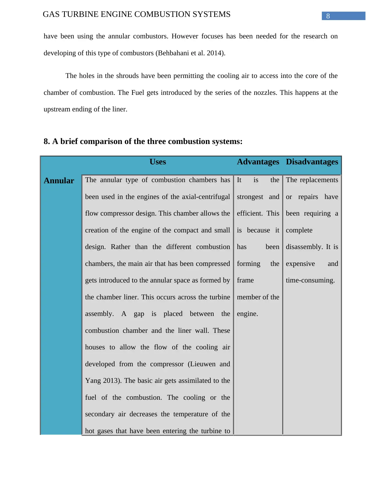
8. A brief comparison of the three combustion systems:
Uses Advantages Disadvantages
Annular The annular type of combustion chambers has
been used in the engines of the axial-centrifugal
flow compressor design. This chamber allows the
creation of the engine of the compact and small
design. Rather than the different combustion
chambers, the main air that has been compressed
gets introduced to the annular space as formed by
the chamber liner. This occurs across the turbine
assembly. A gap is placed between the
combustion chamber and the liner wall. These
houses to allow the flow of the cooling air
developed from the compressor (Lieuwen and
Yang 2013). The basic air gets assimilated to the
fuel of the combustion. The cooling or the
secondary air decreases the temperature of the
hot gases that have been entering the turbine to
It is the
strongest and
efficient. This
is because it
has been
forming the
frame
member of the
engine.
The replacements
or repairs have
been requiring a
complete
disassembly. It is
expensive and
time-consuming.
have been using the annular combustors. However focuses has been needed for the research on
developing of this type of combustors (Behbahani et al. 2014).
The holes in the shrouds have been permitting the cooling air to access into the core of the
chamber of combustion. The Fuel gets introduced by the series of the nozzles. This happens at the
upstream ending of the liner.
8. A brief comparison of the three combustion systems:
Uses Advantages Disadvantages
Annular The annular type of combustion chambers has
been used in the engines of the axial-centrifugal
flow compressor design. This chamber allows the
creation of the engine of the compact and small
design. Rather than the different combustion
chambers, the main air that has been compressed
gets introduced to the annular space as formed by
the chamber liner. This occurs across the turbine
assembly. A gap is placed between the
combustion chamber and the liner wall. These
houses to allow the flow of the cooling air
developed from the compressor (Lieuwen and
Yang 2013). The basic air gets assimilated to the
fuel of the combustion. The cooling or the
secondary air decreases the temperature of the
hot gases that have been entering the turbine to
It is the
strongest and
efficient. This
is because it
has been
forming the
frame
member of the
engine.
The replacements
or repairs have
been requiring a
complete
disassembly. It is
expensive and
time-consuming.
⊘ This is a preview!⊘
Do you want full access?
Subscribe today to unlock all pages.
Trusted by 1+ million students worldwide
9GAS TURBINE ENGINE COMBUSTION SYSTEMS
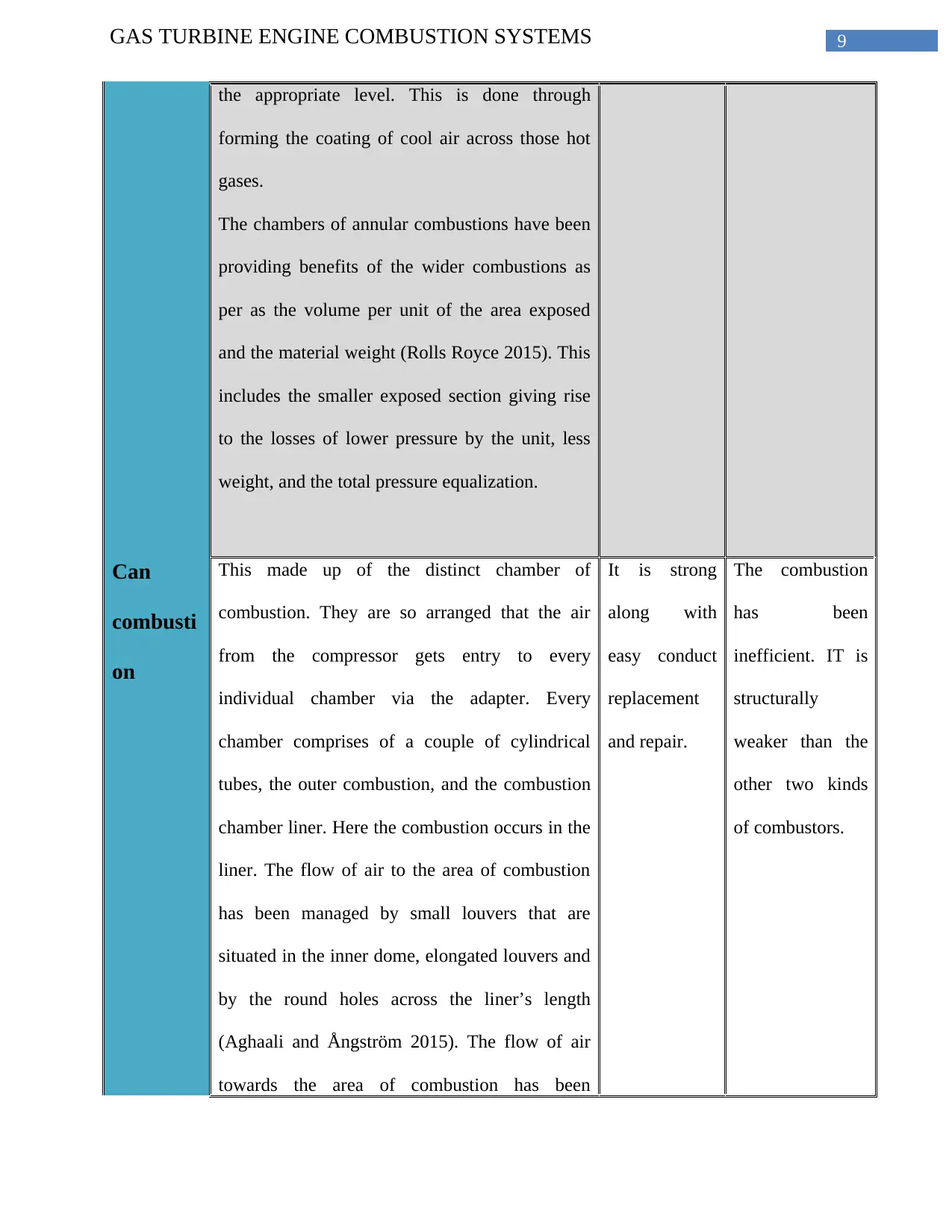
the appropriate level. This is done through
forming the coating of cool air across those hot
gases.
The chambers of annular combustions have been
providing benefits of the wider combustions as
per as the volume per unit of the area exposed
and the material weight (Rolls Royce 2015). This
includes the smaller exposed section giving rise
to the losses of lower pressure by the unit, less
weight, and the total pressure equalization.
Can
combusti
on
This made up of the distinct chamber of
combustion. They are so arranged that the air
from the compressor gets entry to every
individual chamber via the adapter. Every
chamber comprises of a couple of cylindrical
tubes, the outer combustion, and the combustion
chamber liner. Here the combustion occurs in the
liner. The flow of air to the area of combustion
has been managed by small louvers that are
situated in the inner dome, elongated louvers and
by the round holes across the liner’s length
(Aghaali and Ångström 2015). The flow of air
towards the area of combustion has been
It is strong
along with
easy conduct
replacement
and repair.
The combustion
has been
inefficient. IT is
structurally
weaker than the
other two kinds
of combustors.
Paraphrase This Document
Need a fresh take? Get an instant paraphrase of this document with our AI Paraphraser
10GAS TURBINE ENGINE COMBUSTION SYSTEMS
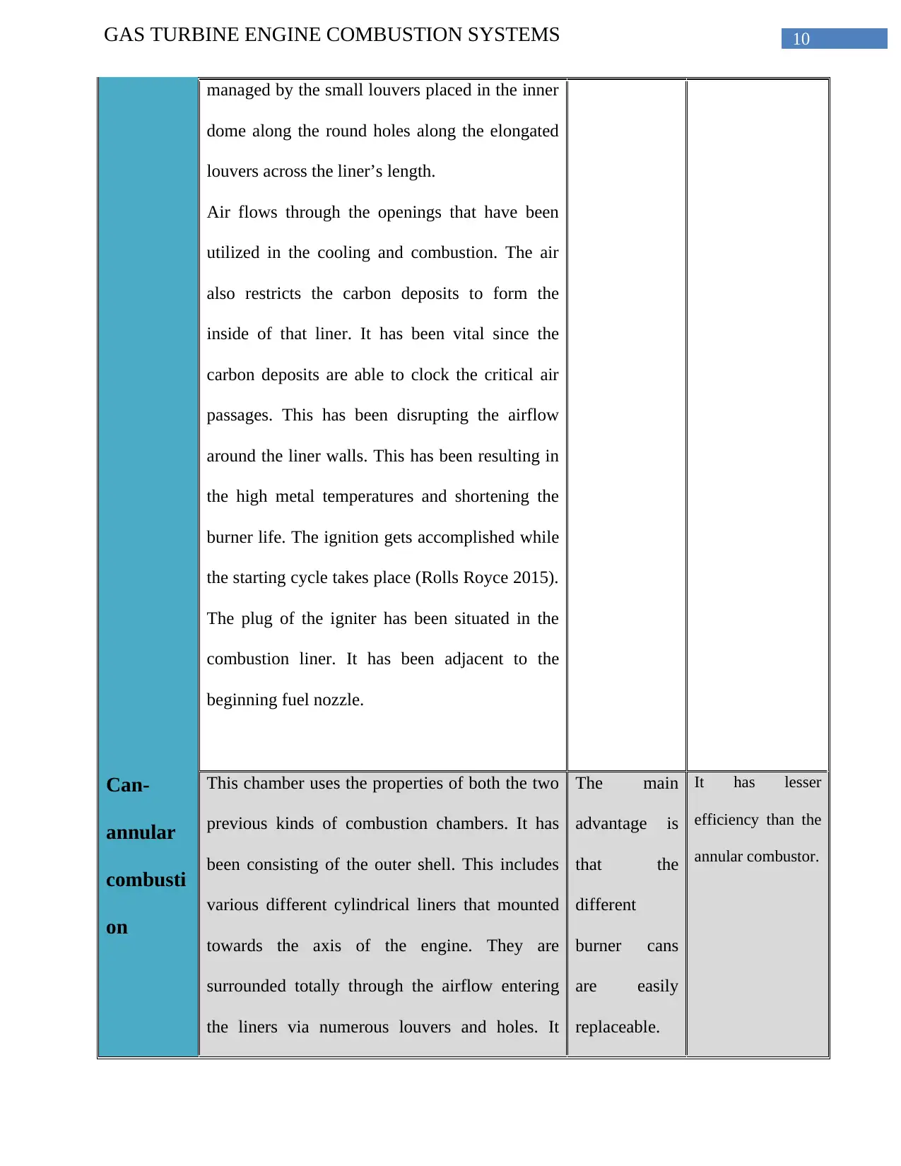
managed by the small louvers placed in the inner
dome along the round holes along the elongated
louvers across the liner’s length.
Air flows through the openings that have been
utilized in the cooling and combustion. The air
also restricts the carbon deposits to form the
inside of that liner. It has been vital since the
carbon deposits are able to clock the critical air
passages. This has been disrupting the airflow
around the liner walls. This has been resulting in
the high metal temperatures and shortening the
burner life. The ignition gets accomplished while
the starting cycle takes place (Rolls Royce 2015).
The plug of the igniter has been situated in the
combustion liner. It has been adjacent to the
beginning fuel nozzle.
Can-
annular
combusti
on
This chamber uses the properties of both the two
previous kinds of combustion chambers. It has
been consisting of the outer shell. This includes
various different cylindrical liners that mounted
towards the axis of the engine. They are
surrounded totally through the airflow entering
the liners via numerous louvers and holes. It
The main
advantage is
that the
different
burner cans
are easily
replaceable.
It has lesser
efficiency than the
annular combustor.

11GAS TURBINE ENGINE COMBUSTION SYSTEMS
indicates that the air is mixed with the fuel
(Liden, 2017). This has been sprayed under the
pressure from the nozzles of the fuels. The
mixture of the fuel-air has been ignited by the
igniter plugs. The flame is then driven by the
crossover tubes to the residual liners. The casing
assembly at the inner part provides both the heat
shield and support. Thus the oil runs through it.
9. Other cooling airflow arrangements used to cool combustion systems:
Some of the additional methods are discussed below:
Convective Cooling by External Airflow:
The arrangement of cooling is a very simple and convenient for arranging and is very
commonly used. This has been particularly appropriate for the straight through tubes of combustion-
chamber flames. Here the dilution air is forced to flow through the annular passage (Arc.aiaa.org,
2017). This is the bounding wall surface that is needed to be cooled. Further, there is the convective
process of heat-transfer between the hot wall and the air. The former one gains an equilibrium
temperature. This has been dependent on the tile ratio of the rates of heat-transfers on the two sides
(Rolls Royce 2015). However, the passage of cooling –air has not been necessary to be annular. This
has been that in the situation of the chamber of the cylindrical combustion. However, it has been
⊘ This is a preview!⊘
Do you want full access?
Subscribe today to unlock all pages.
Trusted by 1+ million students worldwide
1 out of 18
Related Documents


Your All-in-One AI-Powered Toolkit for Academic Success.
+13062052269
info@desklib.com
Available 24*7 on WhatsApp / Email
![[object Object]](/_next/static/media/star-bottom.7253800d.svg)
Unlock your academic potential
Copyright © 2020–2026 A2Z Services. All Rights Reserved. Developed and managed by ZUCOL.