Aircraft Systems: Communication, Radar, and Flight Control
VerifiedAdded on 2023/06/10
|19
|4228
|494
Report
AI Summary
This report provides a comprehensive overview of various aircraft systems. It begins with an explanation of the relationship between frequency, wavelength, and velocity, followed by a discussion of the functional elements of AM receivers and transmitters. The report then delves into aircraft communication systems, including the VHF Data Link and key features of aircraft voice communication systems. It also covers essential flight instruments such as the pilot static system, compass systems, and gyroscopic systems, along with flight director and navigation systems. Furthermore, the report analyzes primary and secondary radar systems, the function of a yaw damper, and the use of radar in air traffic control, including the benefits of ADS-B. The report concludes with an examination of closed-loop feedback in automatic flight control systems and key pilot control modes, including autopilot altitude setting and management.
AIRCRAFT
By Name
Course
Instructor
Institution
Location
Date
By Name
Course
Instructor
Institution
Location
Date
Paraphrase This Document
Need a fresh take? Get an instant paraphrase of this document with our AI Paraphraser
P1: The relationship between frequency, wavelength and velocity
The wavelength of a wave is the distance between two points on the wave’s crest or trough while
the frequency of a wave is a measure of the number of complete oscillations in one second. The
periodic time of a wave (T) is the time taken for one complete cycle. There tends to be a close
relationship between the wavelength and the frenzy of electromagnetic waves. Frequency is
inversely proportional to the wavelength such that the higher the frequency the shorter the
wavelength. Since all the electromagnetic waves that are moving through a space do so at the
same speed, the wavelength determines the number of the wave crests that pass through a given
point. That number which is also the frequency tends to be greater when the wavelength is short
as compared to when it is long Čokorilo, Mirosavljević and Gvozdenović 2011. The equation
c = f relates the wavelength, the frequency and the velocity of electromagnetic waves. In the
equation, is the wavelength, f the frequency and c, the speed of light.
P2: Functional elements of an AM receiver and transmitter
A radio receiver refers to an electronic circuit that is used for receiving radio waves and
changing the information carried by the waves into forms that are usable. The circuit works by
rejecting unwanted signals. The carrier signal is demodulated to get back to the initial
modulating signal. AM receivers are electronic circuits that are used in receiving Amplitude
Modulated signals and their range of the receiver is from 535 KHz to 1705 KHz. AM receivers
are simple but require synchronization.
The functional elements of the receiver include:
Power supply which serves to offer the needed electrical power for the operation of the
transmitter
Modulator which adds helpful information to the carrier wave which is done in two main
ways, through amplitude modulation which results into small decreases or increases in
the intensity of the carrier wave.
Oscillator serves to create alternating current at the frequency of transmission by the
transmitter. The oscillator in most cases creates sine wave which is known as carrier
wave.
Amplifier amplifies the already modulated carrier wave so as to enhance its power. A
higher power of the amplifier increases the power of the broadcasting.
Antenna changes the amplified signals into radio waves
The functional elements of the receiver include:
Tuner which aids in the extraction of signals of a certain frequency from a mix of
numerous signals having various frequencies
Antenna which is used in trapping the radio waves and is in most cases simply a length of
wire
RF amplifier is used in the amplification of the signals of the very weak radio frequency
from the antenna to enable processing of the signals by the tuner.
Audio amplifier is used in the amplification of the weak signals which are generated from
the detector to enable them being heard.
Detector is used for creating a distinction between the audio information and the carrier
wave which is normally done using a diode which work by rectifying the current in AM
receivers.
⊘ This is a preview!⊘
Do you want full access?
Subscribe today to unlock all pages.
Trusted by 1+ million students worldwide
Radio data-link system for use in an aircraft
The VHF Data Link has recently undergone an upgrade in which there is an addition of Mode 2
data also called the VDL Mode 2 capability. VDL Mode 2 is a term that is used in explaining a
suite of protocols of air ground which are used in the enhancement of the rate of data of the air-
ground link to about 31500 bits per second. It permits changing from an infrastructure that
depends on character oriented ACARS protocols for the delivery of end to end messages to one
which adopts the use of bit oriented Aeronautical Telecommunications Network protocols that
make use of the same VHF ground and aircraft radios.
P3: The key features for an aircraft voice communication system include:
Video monitoring
Capability to multi monitor
Configurable graphical elements including buttons, windows and widgets
Transparency function
DA and IA capability
Indication of status for the DA keys
A set of accessories that is complete and includes handset, loudspeakers, handset and disk
microphone
A separate intercom, telephone and radio sections
VESA standard is availed
Role based or multiple user profiles that have access by the use of user log in
P5
Paraphrase This Document
Need a fresh take? Get an instant paraphrase of this document with our AI Paraphraser
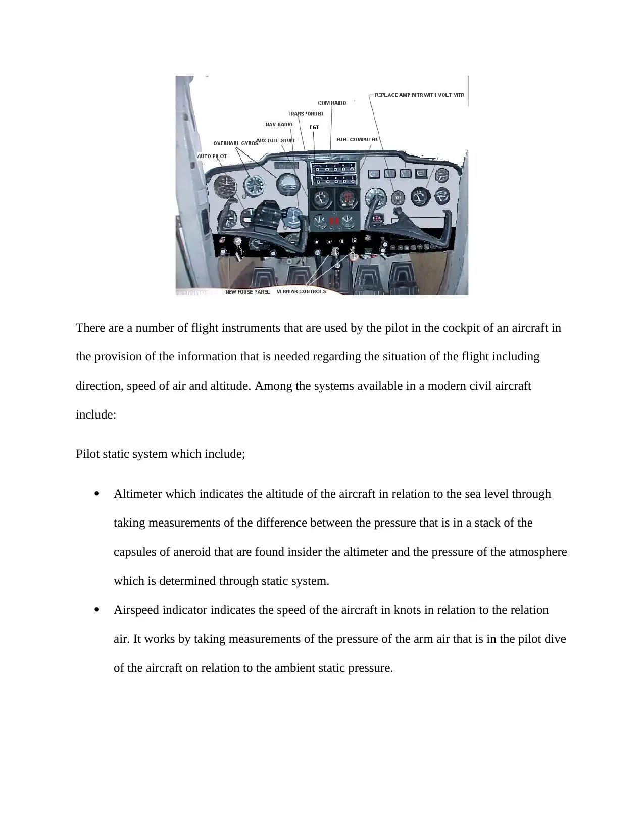
There are a number of flight instruments that are used by the pilot in the cockpit of an aircraft in
the provision of the information that is needed regarding the situation of the flight including
direction, speed of air and altitude. Among the systems available in a modern civil aircraft
include:
Pilot static system which include;
Altimeter which indicates the altitude of the aircraft in relation to the sea level through
taking measurements of the difference between the pressure that is in a stack of the
capsules of aneroid that are found insider the altimeter and the pressure of the atmosphere
which is determined through static system.
Airspeed indicator indicates the speed of the aircraft in knots in relation to the relation
air. It works by taking measurements of the pressure of the arm air that is in the pilot dive
of the aircraft on relation to the ambient static pressure.
Vertical speed indicator also known as the variometer is used in detecting the changes in
the pressure of the air and shows such information to the pilot in the form of a rate of
climb as measured in knots, feet per minute or meters per second
Compass systems which include;
Magnetic compass that is used in indicating the heading of the aircraft in relation to the
magnetic north
Gyroscopic systems which include;
Attitude indicator also called artificial horizon, used in the indication of the relation of
the aircraft to the horizon. Such information helps the pilot in telling if the wings of the
plane are label and if the nose of the plane is pointing below or above the horizon.
Heading indicator also called the directional gyro is used in demonstrating the heading of
the aircraft in relation to the magnetic north upon setting using a compass. Drift errors
from procession are caused by bearing friction which requires periodical correction by
ensuring that the instrument is calibrated to the magnetic compass Poles, Nuic and
Mouillet 2010.
Turn indicator includes the turn coordinator and the turn and slip indicator which are both
used in the indication of the rotation of the aircraft about the longitudinal axis. They
encompass an inclinometer which is used in the indication if the aircraft is in a slip, skid
or coordinated flight. There are also additional marks used for indicating a standard rate
turn.
Flight director systems include Attitude Director Indicator and Horizontal Situation Indicator.
The Horizontal Situation Indicator brings together the magnetic compass having navigation
⊘ This is a preview!⊘
Do you want full access?
Subscribe today to unlock all pages.
Trusted by 1+ million students worldwide
signals with a Glide slope. The Attitude Director Indicator indicates altitude using a set of
computer driven steering bars, which acts as a reliever of tasks during instrumentation flight.
Navigation systems include Nondirectional Radio Beacon and Very-High Frequency
Omnidirectional Range. Very-High Frequency Omnidirectional Range
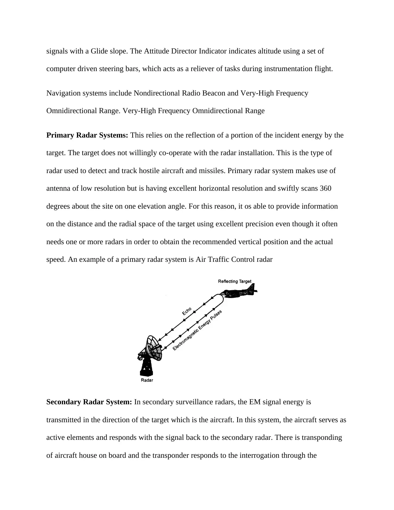
Primary Radar Systems: This relies on the reflection of a portion of the incident energy by the
target. The target does not willingly co-operate with the radar installation. This is the type of
radar used to detect and track hostile aircraft and missiles. Primary radar system makes use of
antenna of low resolution but is having excellent horizontal resolution and swiftly scans 360
degrees about the site on one elevation angle. For this reason, it os able to provide information
on the distance and the radial space of the target using excellent precision even though it often
needs one or more radars in order to obtain the recommended vertical position and the actual
speed. An example of a primary radar system is Air Traffic Control radar
Secondary Radar System: In secondary surveillance radars, the EM signal energy is
transmitted in the direction of the target which is the aircraft. In this system, the aircraft serves as
active elements and responds with the signal back to the secondary radar. There is transponding
of aircraft house on board and the transponder responds to the interrogation through the
computer driven steering bars, which acts as a reliever of tasks during instrumentation flight.
Navigation systems include Nondirectional Radio Beacon and Very-High Frequency
Omnidirectional Range. Very-High Frequency Omnidirectional Range
Primary Radar Systems: This relies on the reflection of a portion of the incident energy by the
target. The target does not willingly co-operate with the radar installation. This is the type of
radar used to detect and track hostile aircraft and missiles. Primary radar system makes use of
antenna of low resolution but is having excellent horizontal resolution and swiftly scans 360
degrees about the site on one elevation angle. For this reason, it os able to provide information
on the distance and the radial space of the target using excellent precision even though it often
needs one or more radars in order to obtain the recommended vertical position and the actual
speed. An example of a primary radar system is Air Traffic Control radar
Secondary Radar System: In secondary surveillance radars, the EM signal energy is
transmitted in the direction of the target which is the aircraft. In this system, the aircraft serves as
active elements and responds with the signal back to the secondary radar. There is transponding
of aircraft house on board and the transponder responds to the interrogation through the
Paraphrase This Document
Need a fresh take? Get an instant paraphrase of this document with our AI Paraphraser
transmission of the codes reply of the back signal. The information contained in such response
includes identification code, altitude among other. The secondary radars system works by
transmitting pules and receiving digital data which emanate from the aircraft transponder. Such
transponders are then used in the determination of the identity of the flight for example in
military operations; examples of secondary radar systems include Identification Friend or Foe
Radar, IFF Radar.
Function of a yaw damper
A yaw damper is an instrument that is used in most aircraft in damping or reducing the rolling or
yawing oscillations called the Dutch roll. It is composed of yaw-rate sensors and a process which
relay signals to an actuator that os linked to the rudder.
Use of Radar in Air Traffic Control
There are two radar types that are used by Air Traffic Control: Primary Surveillance Radar and
Secondary Surveillance Radar. Primary Surveillance Radar makes use of radio transmitter and
receiver that are located at the same ground base. The transmitter is used in the emission of radio
waves which are then reflected back to the solid objects such as the aircraft. These reflected
waves are then picked up by the nearby and associated co-located receiver Kerczewski and
Griner 2012. Secondary Surveillance Radar is fitted with a device called a transponder which is
used in the electrical transmission of data including altitude, speed and call sign. Secondary
Surveillance Radar is a system that is based on the computer and depends on the interface
between the ATC computer that is based on the grounds and the transponder. This system does
not entail reflection of waves.
Benefits of ADS-B as a means of providing real-time data
Expense: The ground stations of ADS-B are relatively cheaper with regard to their
installation as well as operation as compared to both the secondary and primary radar
systems that are used for aircraft by ATC
Traffic: It is possible to have a view of the traffic information by a pilot when using
ADS-B on the information on the surrounding aircraft. Such information available
includes speed, distance, altitude, heading of the aircraft.
Flight information: There is transmission of readable information by the flight
information service broadcast, FIS-B. Such information includes temporary flight
restrictions and NOTAMS.
Weather: Aircraft that has universal access transceiver installed with them are able to
receive the reports on weather and the radar of the weather using the flight
information service broadcast.
Reason for using closed loop feedback in automatic flight control systems
A closed loop system is a control system that adopts the concept of open loop system as the
forward path but is composed of one or more feedback loops or paths that are found between its
input and output. A closed loop feedback is used in an aircraft to aid in the automatic
achievement and maintenance of the desired conditions of output through making a comparison
with the actual condition. This is achieved through the generation of error signal which tends to
be the difference between the reference input and the output.
Key pilot control modes
⊘ This is a preview!⊘
Do you want full access?
Subscribe today to unlock all pages.
Trusted by 1+ million students worldwide
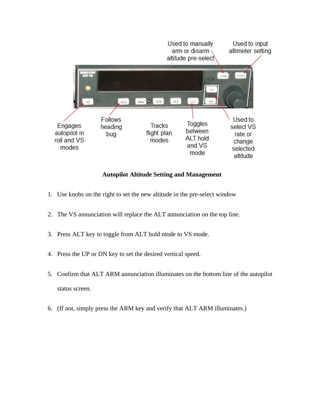
Autopilot Altitude Setting and Management
1. Use knobs on the right to set the new altitude in the pre-select window
2. The VS annunciation will replace the ALT annunciation on the top line.
3. Press ALT key to toggle from ALT hold mode to VS mode.
4. Press the UP or DN key to set the desired vertical speed.
5. Confirm that ALT ARM annunciation illuminates on the bottom line of the autopilot
status screen.
6. (If not, simply press the ARM key and verify that ALT ARM illuminates.)
Paraphrase This Document
Need a fresh take? Get an instant paraphrase of this document with our AI Paraphraser
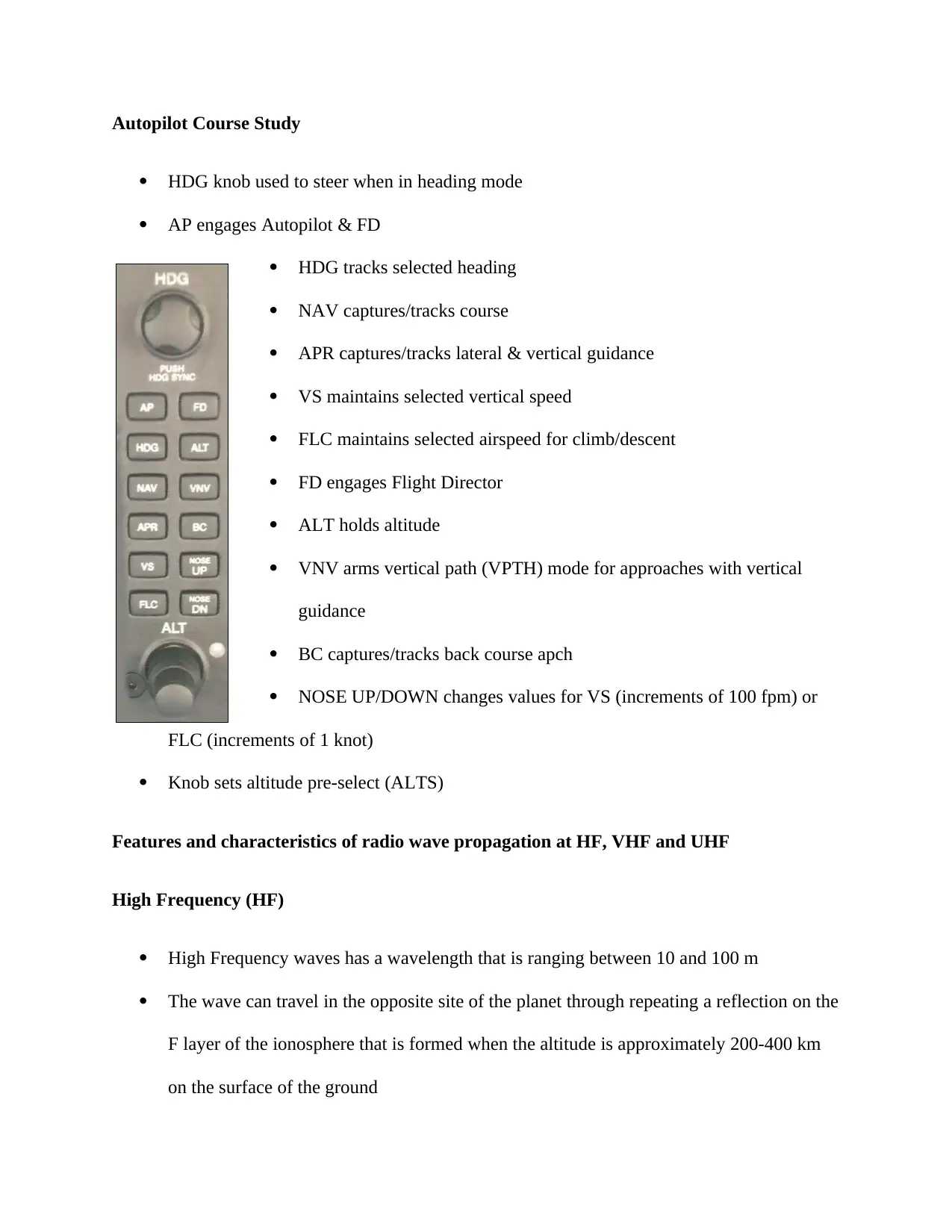
Autopilot Course Study
HDG knob used to steer when in heading mode
AP engages Autopilot & FD
HDG tracks selected heading
NAV captures/tracks course
APR captures/tracks lateral & vertical guidance
VS maintains selected vertical speed
FLC maintains selected airspeed for climb/descent
FD engages Flight Director
ALT holds altitude
VNV arms vertical path (VPTH) mode for approaches with vertical
guidance
BC captures/tracks back course apch
NOSE UP/DOWN changes values for VS (increments of 100 fpm) or
FLC (increments of 1 knot)
Knob sets altitude pre-select (ALTS)
Features and characteristics of radio wave propagation at HF, VHF and UHF
High Frequency (HF)
High Frequency waves has a wavelength that is ranging between 10 and 100 m
The wave can travel in the opposite site of the planet through repeating a reflection on the
F layer of the ionosphere that is formed when the altitude is approximately 200-400 km
on the surface of the ground
High Frequency is used in ocean vessel communication, amateur radio communication,
international broadcasting as well as aeronautical communication since it allows long
distance communication
Very High Frequency (VHF)
Very High Frequency wave has a wavelength ranging between 1, and 10 m
It propagates in a straightforward manner and does not reflect on the ionosphere while it
gets to behind the mountains or buildings that are to some extent
Since it is able to carry more information that the high frequency waves it is applied in
VHF TV broadcasting, mobile communication and FM broadcasting
Ultra High Frequency (UHF)
Has a wavelength of between 10 cm and 1 m
Has stronger straightforwardness as compared to short waves while it gets to behind the
mountains or buildings that are to some extent
Applicable in mobile communication due to its ability to transmit very large amount of
information using small antennas, receivers and transmitters
It is also applicable in UHF TV broadcasting
Double sideband suppressed carrier transmission
This is a transmission in which the production of frequencies by amplitude modulation occurs in
a symmetrically spaced manner over an below the frequency of the carrier and the levels of the
carrier is lowered to the lowest practical level which basically means making it completely
suppressed. The wave carrier is not transmitted in Double sideband suppressed carrier
⊘ This is a preview!⊘
Do you want full access?
Subscribe today to unlock all pages.
Trusted by 1+ million students worldwide
1 out of 19
Related Documents


Your All-in-One AI-Powered Toolkit for Academic Success.
+13062052269
info@desklib.com
Available 24*7 on WhatsApp / Email
![[object Object]](/_next/static/media/star-bottom.7253800d.svg)
Unlock your academic potential
Copyright © 2020–2026 A2Z Services. All Rights Reserved. Developed and managed by ZUCOL.