Aircraft Design Report: Open Rotor Engine and Tail Empennage
VerifiedAdded on 2023/04/20
|16
|4980
|160
Report
AI Summary
This report delves into the intricacies of aircraft design, commencing with the determination of aircraft size and the subsequent geometrical specifications of the tail empennage. The report then progresses to encompass the utilization of sketching and coding methodologies, particularly within the context of MATLAB. Furthermore, it elucidates the operational mechanisms inherent in open rotor engine design. The document provides a comprehensive analysis of the factors influencing aircraft performance, including lift coefficients, airspeed, and structural considerations. Detailed calculations and design choices are presented, such as the selection of airfoil sections, aspect ratios, and sweep angles for the horizontal and vertical tails. The report also includes the discussion of fuselage design, loading conditions, and safety factors. The report emphasizes the importance of the tail empennage assembly, including the fin, tailplane, and fuselage connections, in ensuring structural integrity and aerodynamic stability. The report concludes with reflections on the design process and outlines potential future steps for further research and development in the field of aircraft engineering. The report includes reference list at the end.

MATLAB
Paraphrase This Document
Need a fresh take? Get an instant paraphrase of this document with our AI Paraphraser

Table of Contents
1. Design size of the aircraft.......................................................................................................3
2. Geometrical information of tail empennage...........................................................................6
3. Sketching and Coding............................................................................................................7
4. Working of open rotor engine design...................................................................................10
5. Reflection and future steps...................................................................................................11
Reference List..........................................................................................................................13

1. Design size of the aircraft
An airplane normally flies when the lift of coefficient matches L=12ρv2ACL. V indicates the
airspeed, which combines the speed of the plane with wind speed ρ≈1kg m−3ρ≈1kg m−3
which must be in minimum 5km height. It is needed to remember that most planes can reach
up to 10 km. An area and CL is a combination of the coefficient with a typical value which
needs to be lower than 2. It might change innovation in technology. The only factors that
influence are v and A. The only factors work here is vv and AA. However, AA is increased, the
mass mm will also increase faster than AA area because more material is needed in order to
avoid the plane from breaking down. The Increase of AA quadratically gives more than in
mm, and hence the LL is needed tooi.
The design process usually starts with intend purpose of aircraft. Airlines in commercial
sector design aircraft for carrying a passenger, cargo payload where fuel efficiency is
moderate. On the other hand, fighter jets are designed to maintain high performance
consistently in order to provide enough support to troops. Some aircraft follow specific
mission such as amphibious airplanes. This kind of airplanes has a unique system and design
that allows them to use and operate in land and water. Examples of this kind of airplanes are
Harrier Jump Jet etc. However, it is needed to remember that some rules and regulations must
be followed in aircraft design.
Aircraft design follows fuselage and tail sizing which follows a number of stages. This
method follows the calculation of diameter=3.75m, length= 44m. The first method is the
preliminary horizontal and vertical tail sizing. These two lines are designed to set stability.
The surface is movable in namely elevator and controlling rudder provide. Horizontal and
vertical tails banks on their size. However, sizing preliminary of the two tails follows these
steps. Almost all airplanes have 25% T-tail. This has some advantages. Horizontal tail plays
as end plate in a vertical line. Horizontal tail maintains distance from wing wake. The tail
goes to wake wing in case of high angle attack. The horizontal tail takes in the middle form
of vertical tail and there it acts as a cruciform tail. Vertical tails consist of two parts. H-tail
and triple tail which helps to provide the effect of the end plate. V-tail surfaces combine
horizontal and vertical tailii.
The next step is the choice of aspect ratio for the horizontal tail. Calculation of wing follows
here.
⊘ This is a preview!⊘
Do you want full access?
Subscribe today to unlock all pages.
Trusted by 1+ million students worldwide

NACA 65-415
Sref= 166.67 m2
Span= 44.72m
Sweep at LE = 20 degree
Taper ratio of 0.25
Croot = 5.96m, Ctip= 1.49m, Cmac= 4.17m
This chapter follows the method of lift curve in slope. The aim of the horizontal tail is to
give proper stability in Y-axis. Horizontal tail produces much lift and drags in the wing.
Therefore, the horizontal tail aspect ratio must be lower than the wing.
The next point covers choice of taper ratio for the horizontal tail. The induced drag is
supposed to be a low decrease of structural weight becomes easier in the untapered wing.
Aviation aircraft, in general, uses minimum general speediii. This time taper ratio of
horizontal tail becomes lower. Subsonic airplanes sweep wings with the help of horizontal
tail which has a taper ratio between 0.3 to 0.6
Following point is about the choice of a sweep in horizontal tail. Some advantages can be
found in this section such as sweeping in order to increase each number of drag divergence. It
means subsonic airplanes fly in according to match numbers. However, it is needed to
remember that some airplanes follow this method with having moderate chord sweep. It
becomes helpful to increase the tail arm if it is increased in design later stage.
The following step is about airfoil section for the horizontal tail. The elevator and rudder are
the important factors play here. Deflection of both side work in the undeflected position.
Symmetric airfoil section depends on both horizontal and vertical tails. Airfoils are used for
tails especially in Mach numbers of subsonic jets. Mach number of drag divergence of the tail
must be higher in a position of the wing. A symmetrical airfoil is used for primary design.
Horizontal tail incidence is the next step to the way of completing the projectiv. This method
follows below calculation
NACA 64-006
Sh= 47.60m2
Span= 13.60m
Taper ratio of 1.0
Sweep at LE = 0 degree
Croot= 3.50m, Ctip= 3.50m, Cmac= 3.50m
Paraphrase This Document
Need a fresh take? Get an instant paraphrase of this document with our AI Paraphraser

It mainly refers to an angle of between chord reference and horizontal tail in order to
maintain a fuselage line. Choice of horizontal tail incidence refers to cruise, the required lift
from tail in order to make that airplane zero moment pitching. It happens when the low angle
attack is less. The tail lift is produced without deflection of the elevator. The aspect ratio of a
vertical tail is also necessary. It is the same as the fuselage axis when the vertical tail is
attached. Usually, the dorsal fin of aircraft is not included in the vertical tail area.
Choice of sweep for the vertical tail is one of the major points in aircraft designing.
Disadvantages are found in this section. Vertical tail is swept in order to increase the moment
arm. T-tail configuration requires horizontal tail moment arm in case it is increased. Subsonic
airplanes must follow Mach numbers. Vertical stabilizer follows one simple calculationv. The
calculation is given below.
NACA 64-006
Sv= 33.01m2
Span= 4.60m
Taper ratio of 0.53
Sweep at LE= 0 degree
Croot= 4.20m, Ctip= 1.75cm, Cmac= 3.59m
Airfoil section for vertical tail comes next. Symmetrical airfoil is depended on the vertical
and horizontal tail. This is mainly used in aircraft in the aviation sector. High flying airplanes
such as subsonic use number of the thickness ratio. It is usually 2% lower than the usual
value.
The last part of this section is about between angle and chord reference. The value is usually
zero. Airplanes with single engine use propeller combination and this rolling moment need to
be balanced. A counterbalancing moment is not considered as large and it is created by a
vertical tail.

2. Geometrical information of tail empennage
Loading of fuel sage is an important part during designing an aircraft. It is essential to know
about the loading criteria’s and working conditions of aircraft during loading in flight.
Torsion and bending forces may come in the wings and fuselage during landing or taking off.
To the fuselage all major components of aircraft is connected with, like wings, tail, landing
gear and many others. Inertial weight of the flight also affects the structure and fuselage
design. Basic loads on fuselage are considered as cargoes force, aerodynamic forces and
extreme pressure of cabin. Factor of safety for the fuselage is also considered during
designing an aircraft. According to the torque, bending moment and shear forces sustaining
capacity of aircraft, changes of their design are made. Horizontal and vertical tail wing are
considered in the shear force affect mainly. In general forces act on the wings are drag force,
lift force, inertia forces and force due to engine draft.
In case of a structural issue concerning aircraft, it can be said that empennage consists of
compete assembly of a tail. This kinds of assembly include ailfin, the tailplane and different
parts of the fuselage to which are attached and are initiated in a perfect way. The entire
empennage consists of front sections that are embedded with tailplane or the horizontal
stabilizers that are provided in the pitch in constant motion. These kinds of engagement in the
airplane generally provide a proper geometric pattern for the overall structural complexities.
This is the basic part that needs to be proper in order to make the structural competency in a
similar pattern as are required within the stage of a proposal. This kinds of proposal are
generally being made by the campaign and social structures of the plane that are being
considered through numerical evaluation.
The entire tail assembly is being configured in order to have a collaboration of the terms and
condition which are required to make the airplane fly. Such geometrical configuration needs
to be produced within the rate of inflation that will suit with a proper valuation analysis. This
will also provide stability in the overall structural configuration and order of pitch. According
to the assignment needs, it has been clearly assumed that the pitch will remain constant
throughout the aerodynamic structure. It can be said that if the pitch remains constant, then
there should be a rivet pitch that will initiate a frame of cross-sectional dimension on the
overall dynamics issues. This will also ensure that there is actual use of panels in order to
have a perfect order of sufficiency throughout the structural section of the aerodynamics.
⊘ This is a preview!⊘
Do you want full access?
Subscribe today to unlock all pages.
Trusted by 1+ million students worldwide

Therefore, it can be said that the structural components should be assembled in a systematic
manner so as to assemble a tail empennage in a limited pitch curriculum and transparency.
This kinds of activity will initiate a proper understanding of the terms and its function in
order to make the operation successful in a definite pattern. The pitch and stream effect falls
under pressure once in a while when there are a perfect emblem and synchronization in the
overall work and maintenance of the structure. This kinds of an instance are being kept for
the purpose of effective configuration.
The theory is generally dependent on the specific assumptions of panels that are being
considered and are being kept in order to stabilize the perfection of the overall structural
association. Such kind of things carries discrete transverse in the aircraft that are to be
organized and are maintained in a similar way and pattern. The panel or the contrast stringer
geometry involves the ultimate transfusion and analysis of the economic structural
association. There is a need for effective configuration in the outcome of events. This is the
structural association for the optimization in the construction site. Such construction also
resembles varied options for the overall resemblance of the aerodynamic structure and its
behavior in a chronological form. This is the basic part of the maintenance of structural
analysis throughout the overall concurrent state of the airplane and structural analysis.
Therefore, it can be said that there is a need for proper collaboration in the structural
association and possible outcome that is being conferred to the overall subjective analysis in a
validating presumption. This can be said that there is a need for proper analysis in the
corrective measure which has been propounded for the sake of structural analysis to support
the corrective structure. This will also maintain the stringent and the basic balance from the
top to the wings in a varied way.
The frequency of the stringent needs to be maintained for a proper analysis. This will also
inaugurate a balance in the generalization of related components that are associated with the
programmingvi. The tail empennage is also associated with the component analysis and meta-
analysis in the inward base of the structural association. The tension might be considerably
dependent on the factual components that are provided in a societal basis. This should be the
basic geometrical association in the airplane. It will also conclude to be maintained in order
of specification and assemblance. The engineers associated will be the responsible person in
the ongoing process of geometrical structure.
There exist four types of loads in fuselage. They are discussed below in briefly:
1. The forces of the parts of the plane which are transmitted into the fuselage is considered as
load. This lods are attached to the fuselage.
Paraphrase This Document
Need a fresh take? Get an instant paraphrase of this document with our AI Paraphraser

2. There exists another three loads which are by default for the fuselage itself. Cargoes forces,
various units and parts of the fuselage and the forces which are emits from aerodynamics.
3. From the cabin there also transmitted some forces which is denoted by Delta P. In this load
there contains two types of components one is compartments which are considered as special
and other is channels for the engine.
(Source: https://www.researchgate.net/figure/Loads-present-in-the-aircraft-fuselage-
7_fig1_289045821 )
(Source: https://www.researchgate.net/figure/Loads-present-in-the-aircraft-fuselage-
7_fig1_289045821 )
Matlab coding for bending moment and shear forces for the tail
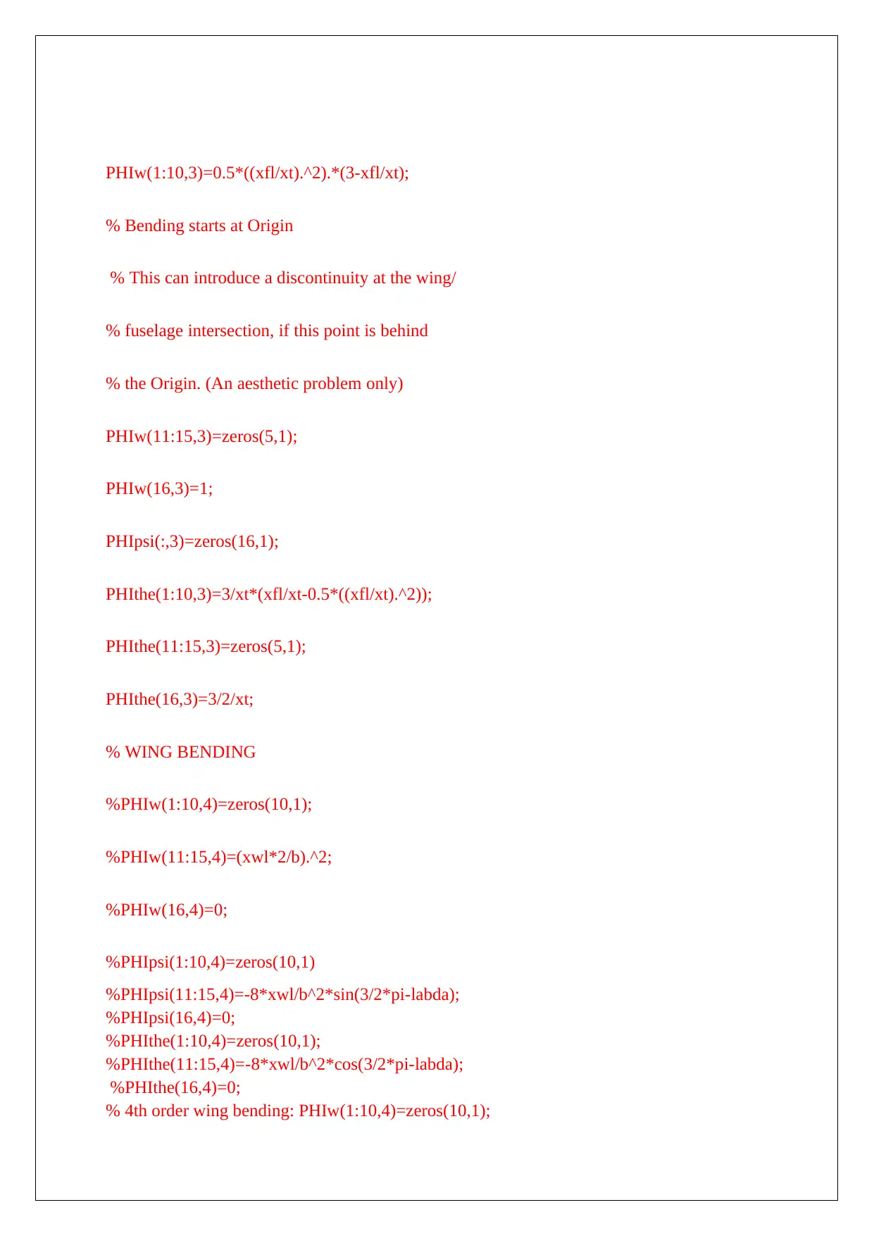
PHIw(1:10,3)=0.5*((xfl/xt).^2).*(3-xfl/xt);
% Bending starts at Origin
% This can introduce a discontinuity at the wing/
% fuselage intersection, if this point is behind
% the Origin. (An aesthetic problem only)
PHIw(11:15,3)=zeros(5,1);
PHIw(16,3)=1;
PHIpsi(:,3)=zeros(16,1);
PHIthe(1:10,3)=3/xt*(xfl/xt-0.5*((xfl/xt).^2));
PHIthe(11:15,3)=zeros(5,1);
PHIthe(16,3)=3/2/xt;
% WING BENDING
%PHIw(1:10,4)=zeros(10,1);
%PHIw(11:15,4)=(xwl*2/b).^2;
%PHIw(16,4)=0;
%PHIpsi(1:10,4)=zeros(10,1)
%PHIpsi(11:15,4)=-8*xwl/b^2*sin(3/2*pi-labda);
%PHIpsi(16,4)=0;
%PHIthe(1:10,4)=zeros(10,1);
%PHIthe(11:15,4)=-8*xwl/b^2*cos(3/2*pi-labda);
%PHIthe(16,4)=0;
% 4th order wing bending: PHIw(1:10,4)=zeros(10,1);
⊘ This is a preview!⊘
Do you want full access?
Subscribe today to unlock all pages.
Trusted by 1+ million students worldwide

PHIw(11:15,4)=1/3*( (1-xwl*2/b).^4 - 4*(1-xwl*2/b) + 3 );
PHIw(16,4)=0;
PHIpsi(1:10,4)=zeros(10,1);
PHIpsi(11:15,4)=-8/3/b*( 1 - (1-xwl*2/b).^3 )*sin(3/2*pi-labda);
PHIpsi(16,4)=0; PHIthe(1:10,4)=zeros(10,1);
PHIthe(11:15,4)=-8/3/b*( 1 - (1-xwl*2/b).^3 )*cos(3/2*pi-labda);
PHIthe(16,4)=0;
% WING TORSION
PHIw(:,5)=zeros(16,1);
PHIpsi(1:10,5)=zeros(10,1);
PHIpsi(11:15,5)=( -4/b^2*xwl.^2 + 4/b*xwl )*cos(3/2*pi-labda)/cw;
% divide by cw for correct units PHIpsi(16,5)=0;
% in state vector ([m]) PHIthe(1:10,5)=zeros(10,1);
PHIthe(11:15,5)=-1*( -4/b^2*xwl.^2 + 4/b*xwl )*sin(3/2*pi-labda)/cw;
% divide by cw for correct units PHIthe(16,5)=0;
% in state vector
End
Parameters for detecting the load
alpha = fltdata(:,2);
beta = fltdata(:,3);
omega = convangvel( fltdata(:,5:7), 'rad/s', 'deg/s' );
alt = fltdata(:,10);
flaps0IAS = 40:10:140;
flaps0CAS = [43 51 59 68 77 87 98 108 118 129 140];
CAS = interp1( flaps0IAS, flaps0CAS, fltdata(:,4) );
[T, a, P, rho]= atmoscoesa( alt );
Vt = correctairspeed( CAS, a, P, 'CAS', 'TAS' );
data = datcomimport( 'astflight.out', true, 0 );
aerotab = {'cyb' 'cnb' 'clq' 'cmq'};
for k = 1:length(aerotab)
for m = 1:data{1}.nmach
for h = 1:data{1}.nalt
data{1}.(aerotab{k})(:,m,h) = data{1}.(aerotab{k})(1,m,h);
end
end
end
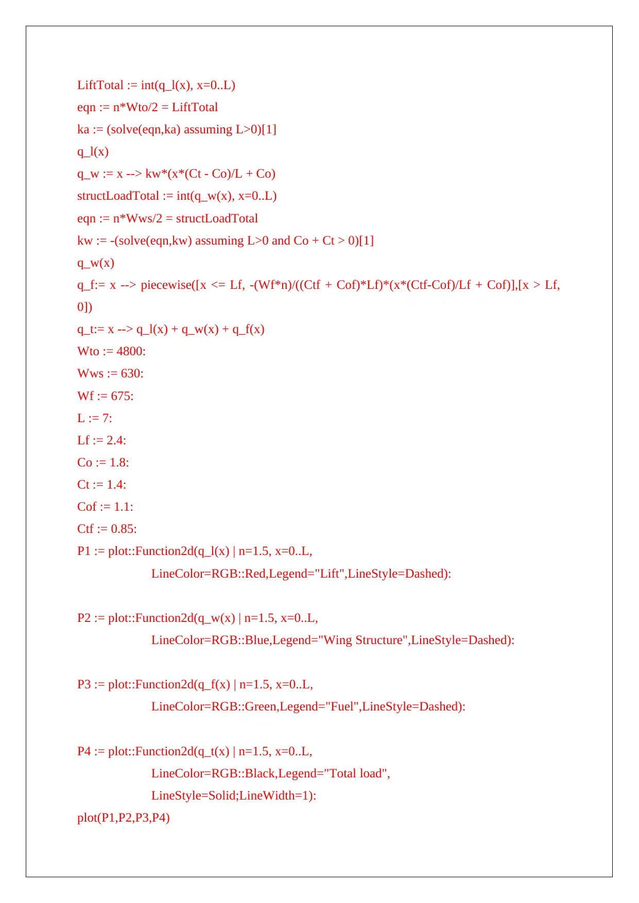
3. Sketching and Coding of Torque Calculation (Bending moment vs
length)
The solution of the wings calculation and their sample coding in Matlab is shown which
gives the below graphs which shows the relation of Bending moment and load with length of
the wing.
q_l:= x --> ka*sqrt(L^2 - x^2)
PHIw(16,4)=0;
PHIpsi(1:10,4)=zeros(10,1);
PHIpsi(11:15,4)=-8/3/b*( 1 - (1-xwl*2/b).^3 )*sin(3/2*pi-labda);
PHIpsi(16,4)=0; PHIthe(1:10,4)=zeros(10,1);
PHIthe(11:15,4)=-8/3/b*( 1 - (1-xwl*2/b).^3 )*cos(3/2*pi-labda);
PHIthe(16,4)=0;
% WING TORSION
PHIw(:,5)=zeros(16,1);
PHIpsi(1:10,5)=zeros(10,1);
PHIpsi(11:15,5)=( -4/b^2*xwl.^2 + 4/b*xwl )*cos(3/2*pi-labda)/cw;
% divide by cw for correct units PHIpsi(16,5)=0;
% in state vector ([m]) PHIthe(1:10,5)=zeros(10,1);
PHIthe(11:15,5)=-1*( -4/b^2*xwl.^2 + 4/b*xwl )*sin(3/2*pi-labda)/cw;
% divide by cw for correct units PHIthe(16,5)=0;
% in state vector
End
Parameters for detecting the load
alpha = fltdata(:,2);
beta = fltdata(:,3);
omega = convangvel( fltdata(:,5:7), 'rad/s', 'deg/s' );
alt = fltdata(:,10);
flaps0IAS = 40:10:140;
flaps0CAS = [43 51 59 68 77 87 98 108 118 129 140];
CAS = interp1( flaps0IAS, flaps0CAS, fltdata(:,4) );
[T, a, P, rho]= atmoscoesa( alt );
Vt = correctairspeed( CAS, a, P, 'CAS', 'TAS' );
data = datcomimport( 'astflight.out', true, 0 );
aerotab = {'cyb' 'cnb' 'clq' 'cmq'};
for k = 1:length(aerotab)
for m = 1:data{1}.nmach
for h = 1:data{1}.nalt
data{1}.(aerotab{k})(:,m,h) = data{1}.(aerotab{k})(1,m,h);
end
end
end
3. Sketching and Coding of Torque Calculation (Bending moment vs
length)
The solution of the wings calculation and their sample coding in Matlab is shown which
gives the below graphs which shows the relation of Bending moment and load with length of
the wing.
q_l:= x --> ka*sqrt(L^2 - x^2)
Paraphrase This Document
Need a fresh take? Get an instant paraphrase of this document with our AI Paraphraser
LiftTotal := int(q_l(x), x=0..L)
eqn := n*Wto/2 = LiftTotal
ka := (solve(eqn,ka) assuming L>0)[1]
q_l(x)
q_w := x --> kw*(x*(Ct - Co)/L + Co)
structLoadTotal := int(q_w(x), x=0..L)
eqn := n*Wws/2 = structLoadTotal
kw := -(solve(eqn,kw) assuming L>0 and Co + Ct > 0)[1]
q_w(x)
q_f:= x --> piecewise([x <= Lf, -(Wf*n)/((Ctf + Cof)*Lf)*(x*(Ctf-Cof)/Lf + Cof)],[x > Lf,
0])
q_t:= x --> q_l(x) + q_w(x) + q_f(x)
Wto := 4800:
Wws := 630:
Wf := 675:
L := 7:
Lf := 2.4:
Co := 1.8:
Ct := 1.4:
Cof := 1.1:
Ctf := 0.85:
P1 := plot::Function2d(q_l(x) | n=1.5, x=0..L,
LineColor=RGB::Red,Legend="Lift",LineStyle=Dashed):
P2 := plot::Function2d(q_w(x) | n=1.5, x=0..L,
LineColor=RGB::Blue,Legend="Wing Structure",LineStyle=Dashed):
P3 := plot::Function2d(q_f(x) | n=1.5, x=0..L,
LineColor=RGB::Green,Legend="Fuel",LineStyle=Dashed):
P4 := plot::Function2d(q_t(x) | n=1.5, x=0..L,
LineColor=RGB::Black,Legend="Total load",
LineStyle=Solid;LineWidth=1):
plot(P1,P2,P3,P4)

AxesTitles = ["Length", "Load (N/m)"],Width=160;Height=120)
read(NOTEBOOKPATH."CalcShear.mu");
shear_force := CalcShear(q_t(x))
plotfunc2d(shear_force | n=1.5, x=0..L, AxesTitles = ["Length", "Shear (N)"])
read(NOTEBOOKPATH."CalcMoment.mu");
bending_moment := CalcMoment(q_t(x))
plotfunc2d(bending_moment | n=1.5, x=0..L, AxesTitles = ["Length", "Moment (N*m)"])
Fig 1: Bending moment vs length in wings
(Source: Created by Author)
i Hahn B, Valentine DT. Essential MATLAB for engineers and scientists. UK: Academic Press; 2016 Sep 1.
ii Gómez HF, Hucka M, Keating SM, Nudelman G, Iber D, Sealfon SC. Moccasin: converting Matlab Ode models to Sbml.
Bioinformatics. 2016 Feb 9(32(12):1905-6.)
iii Haase T, Unruh O, Algermissen S, Pohl M. Active control of counter-rotating open rotor interior noise in a Dornier 728
experimental aircraft. Journal of Sound and Vibration. 2016 Aug 18(376:18-32.)
iv Scheele JT, Ohmann PR, Green AS. A Matlab user-interface tool for modeling herds. European Journal of Physics. 2018
Oct 15(39(6):064004.)
v Seah S, Nimmrichter S, Scarani V. Work production of quantum rotor engines. New Journal of Physics. 2018 Apr
20(20(4):043045.)
vi Van Zante DE. Progress in open rotor research: A US perspective. ASME Turbo Expo 2015: Turbine Technical
Conference and Exposition 2015 Jun 15 American Society of Mechanical Engineers.(pp. V001T01A003-V001T01A003)
⊘ This is a preview!⊘
Do you want full access?
Subscribe today to unlock all pages.
Trusted by 1+ million students worldwide
1 out of 16
Your All-in-One AI-Powered Toolkit for Academic Success.
+13062052269
info@desklib.com
Available 24*7 on WhatsApp / Email
![[object Object]](/_next/static/media/star-bottom.7253800d.svg)
Unlock your academic potential
Copyright © 2020–2026 A2Z Services. All Rights Reserved. Developed and managed by ZUCOL.