Aircraft Wing Evolution: Physics, Innovation, and Operational Analysis
VerifiedAdded on 2023/01/18
|11
|2064
|93
Report
AI Summary
This report provides a comprehensive overview of aircraft wing mechanics, tracing their evolution from early designs to modern innovations. It begins with an introduction to the history of flight, highlighting key milestones and pioneers. The core of the report delves into the physics of flight, analyzing the forces of lift, drag, thrust, and weight, and includes relevant equations like Bernoulli's equation. It then examines pivotal innovations in wing design, evaluating their impact on current aircraft. The report also explores specific mechanical developments, such as the breaking of the sound barrier by Chuck Yeager and the contributions of Da Vinci and the Wright brothers. The importance of fuel efficiency and the use of advanced materials and technologies, such as 3D printing and flexible wings, are also discussed. The report concludes by emphasizing the ongoing advancements in aircraft wing design and their impact on performance and safety. References are provided using the Harvard style.
CONCEPT OF OPERATION OF AIRCRAFT WINGS
PRESENTED BY:
PRESENTED BY:
Paraphrase This Document
Need a fresh take? Get an instant paraphrase of this document with our AI Paraphraser
Introduction:
Aviation science was started 2000 years back but the real development of aviation
and invention of aircraft started in early 1900’s. Leonardo Da Vinci is the first person
to dream about the flying giant carrying passenger in side it. The history of aircraft is
divided into following category (Stalewski, (2006))
Pioneer’s of Flight earliest experiment to 1914
First World war 1914-1918
Aviation between world War 1918-1939
Second World War 1939-1945
Postwar Era 1945 to present day
The aircraft is a flying machine that is capable of flying taking support from air. It
counters the force of gravity by using static lift or by using dynamic lift of an airfoil.
The history of flight development is understanding the dynamic reaction of lifting
surface and reliable engine that can produce sufficient energy to propel the air frame
structure of the aircraft. (C. Nae, V.M. Pricop,(2006))
Aircraft wing has transformed from wooded fabric in Wright Brother’s flyer to
composite materials are used in the advance aircraft manufactured by Boeing, Airbus
etc. Also the geometry of the aircraft wing has done a tremendous evolution. As the
forces on aircraft are drag, thrust, lift and weight, the geometry of the aircraft wing
plays a very important role.
Apart from counter acting the forces, aircraft wing plays significant role in fuel
efficiency. As the geometry and physics of wing improved the payload on the aircraft
decreases, there by the fuel efficiency increases.
Theory of Flight:
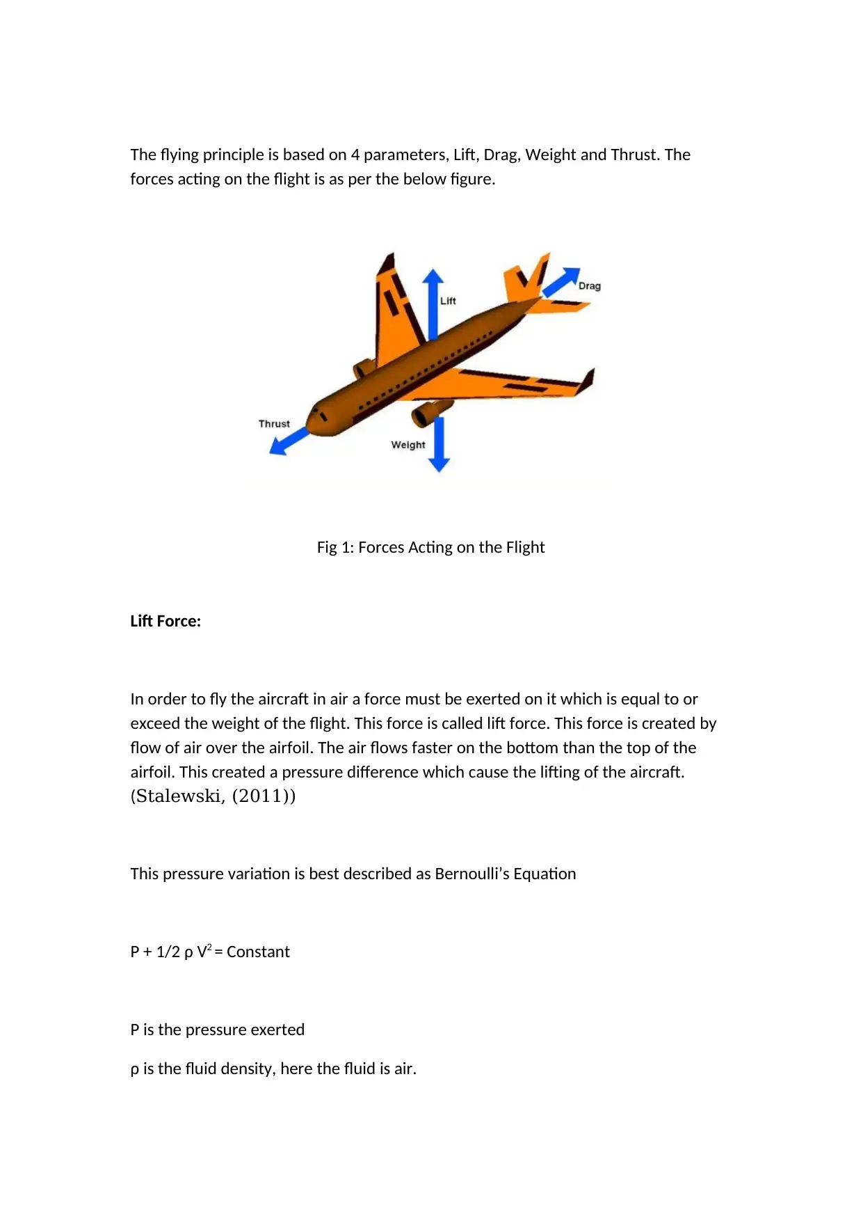
The flying principle is based on 4 parameters, Lift, Drag, Weight and Thrust. The
forces acting on the flight is as per the below figure.
Fig 1: Forces Acting on the Flight
Lift Force:
In order to fly the aircraft in air a force must be exerted on it which is equal to or
exceed the weight of the flight. This force is called lift force. This force is created by
flow of air over the airfoil. The air flows faster on the bottom than the top of the
airfoil. This created a pressure difference which cause the lifting of the aircraft.
(Stalewski, (2011))
This pressure variation is best described as Bernoulli’s Equation
P + 1/2 ρ V2 = Constant
P is the pressure exerted
ρ is the fluid density, here the fluid is air.
⊘ This is a preview!⊘
Do you want full access?
Subscribe today to unlock all pages.
Trusted by 1+ million students worldwide
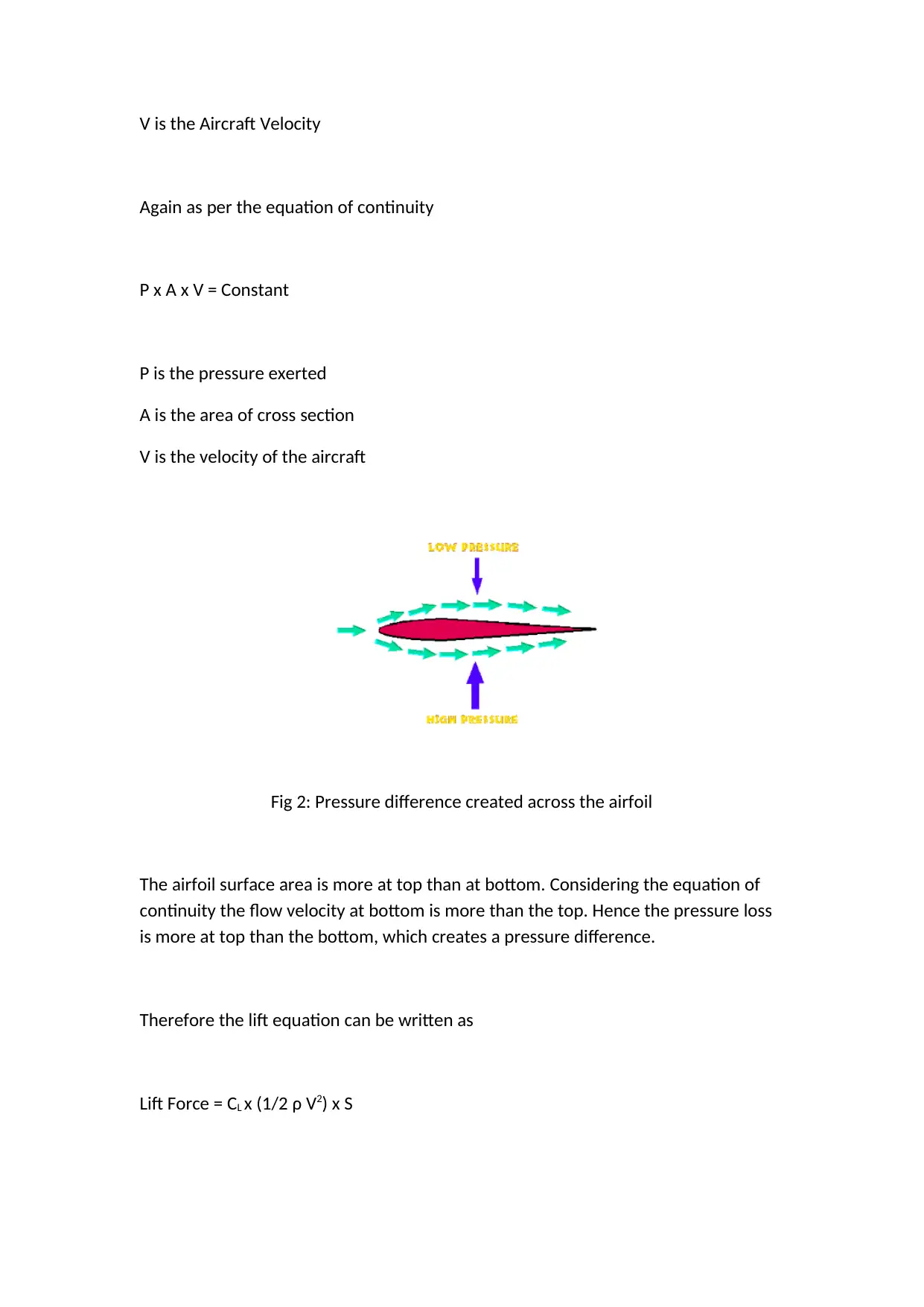
V is the Aircraft Velocity
Again as per the equation of continuity
P x A x V = Constant
P is the pressure exerted
A is the area of cross section
V is the velocity of the aircraft
Fig 2: Pressure difference created across the airfoil
The airfoil surface area is more at top than at bottom. Considering the equation of
continuity the flow velocity at bottom is more than the top. Hence the pressure loss
is more at top than the bottom, which creates a pressure difference.
Therefore the lift equation can be written as
Lift Force = CL x (1/2 ρ V2) x S
Paraphrase This Document
Need a fresh take? Get an instant paraphrase of this document with our AI Paraphraser
CL is the lift co-efficient
S is the wing area
To increase the lift force, the lift co-efficient should be as high as possible.
Drag Force:
Drag force is defined as the resistance force by air when the body is propelled
through air. Pressure at the front side is more than the pressure at the back side. To
reduce this drag force the contact surface should be as smooth as possible. Like lift
force, the drag force is proportional to dynamic pressure and the area of contact.
The drag force is defined as (Sasaki, Obayashi, Sawada, Himero, (1999))
Drag Force = CD x (1/2 ρ V2) x A
CD is the co-efficient of drag force.
Weight Force:
The weight is the limiting factor for the designing aircraft. The aircraft is designed to
carry high payload and the weight is defined by Newton’s second law
Weight W = m x g
m is the mass of the aircraft
g is the acceleration due to gravity.
Thrust Force:
Thermodynamics, Fluid Mechanics, Aero Dynamics and Physics play a important role
in the propulsion of the aircraft. The trust force is described by Newton’s law
Thrust Force F = m x a
m is the weight of the aircraft
a is the acceleration of the aircraft
Energy Calculation of Aircraft:
The total energy of the aircraft flying in the atmosphere is defined by the following
equation
E = 1/2 x m x V2 + m x g x h
m is the mass of the aircraft
V is the velocity at a particular time
g is the acceleration due to gravity
h is the altitude of flying
However the engine mounted on the wing should give additional energy to fly at the
constant height and constant velocity. Extra power is required to overcome the drag
force acting on the aircraft
The extra power needed is defined by
⊘ This is a preview!⊘
Do you want full access?
Subscribe today to unlock all pages.
Trusted by 1+ million students worldwide
P = (dh/dt) m g
dh/dt is the decent speed
As the aircraft decents towards the ground the gliding angle, gliding slope and glide
ration can be calculated from aircraft specification. The glide angle (γ) is related to
the glide slope by tan(γ) and the glide ratio is calculated as the inverse of the glide
slope, cot(γ). (Sznajder, (2010)
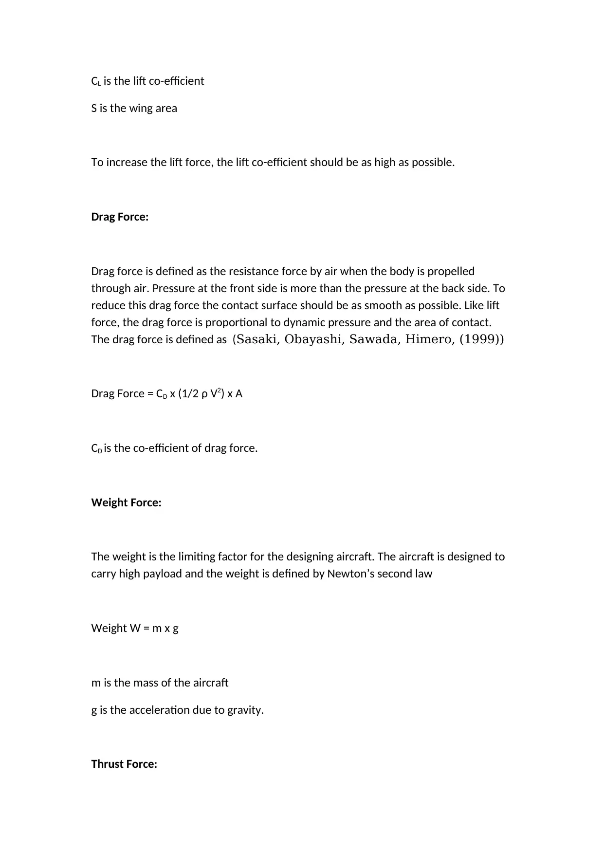
Fuel Efficiency:
The fuel efficiency plays an important role in aircraft design and operation. The fuel
efficiency is affected by payload and design of the aircraft. As the force values
described above increases the resistance to payload decreases thus the fuel
efficiency increases. (Sznajder, (2010))
The below figure represent gain in the fuel efficiency since the inception of
commercial aircraft.
Fig 3: Fuel Efficiency Gain since the evolved of Aircraft
dh/dt is the decent speed
As the aircraft decents towards the ground the gliding angle, gliding slope and glide
ration can be calculated from aircraft specification. The glide angle (γ) is related to
the glide slope by tan(γ) and the glide ratio is calculated as the inverse of the glide
slope, cot(γ). (Sznajder, (2010)
Fuel Efficiency:
The fuel efficiency plays an important role in aircraft design and operation. The fuel
efficiency is affected by payload and design of the aircraft. As the force values
described above increases the resistance to payload decreases thus the fuel
efficiency increases. (Sznajder, (2010))
The below figure represent gain in the fuel efficiency since the inception of
commercial aircraft.
Fig 3: Fuel Efficiency Gain since the evolved of Aircraft
Paraphrase This Document
Need a fresh take? Get an instant paraphrase of this document with our AI Paraphraser
Incorporating Innovation In Aircraft Wing:
The advance technology are used for the design and fabrication of aircraft wings also
some new hardware are used for the aircraft structural monitoring. The advance
technology has a speed and safety impact on the aircraft wing and the physics
behind it. Also during the design and manufacturing of the wings space consideration
is taken for the placing of the sensor and also can accommodate the new more
powerful engine. The aircraft wing design has a significant potential for improvement
and growth. Again, OEMs are using new manufacturing methods, such as 3D printing
and rapid prototyping, to solve this issue, shaping and refining the product to
optimise design and fabrication process. (Rokicki, Stalewski, Żółtak ,(2009))
Recent development in technology and design improvement has sinificant
improvement in aircraft structural improvement. Airbus and Boeing have developed
aircraft wings to reduce the rake and swinging of vortex through air. These usually
take the form of small upward-pointing extensions at the tip of the wings. By
reducing the air disturbance the fuel efficiency has increased by 4-5%. These
advance technology has implemented on 767 aircrafts saving the fuel of 500000
gallons and 4790 tonnes of CO2.
The aircraft wing has undergone a transformation since the Wright Brothers’ first
flight. Most importantly the implementation of advance material and design
technology in aircraft wing. This will increase the pressure difference which will help
the vertical take off of the aircraft and also increases the fuel efficiency. Due to
vertical take off the fuel consumption reduces as the time taken for the flying
altitude decreases and flight takes minimum path to reach that altitude.
Flexible Aircraft Wing:
NASA has done numerous experiment in rotating wing. This rotating wing can rotate
up to 30 degree in both ways. This will save the fuel upto 12%. This rotating wing can
reduce the drag force and lift force required. Also this rotating wing creates a major
pressure difference across the wing.
De-Icing Coatings
Icing over the aircraft body is a major problem in the aviation industries. By icing
over the wings it is pretty difficult to operate the flaps which increases the load on
the hydraulic cylinders. Also this increases the payload of the aircraft.
With the advancement of technology one gel coating is invented which prevents the
icing over the wings and body of the aircraft. This reduces the maintenance time as
well as the payload.
Breaking of the sound barrier by Chuck Yeager:
Charle’s Yeager is the first person to exceed the speed of the sound in flight. He
made this history on Oct 14, 1947 prior to the second world war. He made this
historic journey on X-1 Rocket flight built by Bell Aircraft Company. X-1 Flight was
powered by Torbo jet Miles M52. This flight was capable of flying at 1300 Km/hr at
35000 ft.
Conclusion:
The aircraft wings have made a significant development since it’s inception. It started
with simple profile wooded wing in wright brother’s first flight to now a days we are
using composite materials wings. The aircraft wings have been deployed with sensor
⊘ This is a preview!⊘
Do you want full access?
Subscribe today to unlock all pages.
Trusted by 1+ million students worldwide
to monitor the weather and wind speed to function or operate the wings and airfiols
accordingly.
With the advance technology and rapid proto typing it is easier and safe to make a
prototype and test it at real condition before implementing it at real time. Also
developments are done in the innovation of composite materials. NASA is
developing a composite material which don’t need the de-icing coating over it and
can sustain high temperature. This will reduce the maintenance cast as well as
reduce the payload.
Reference:
Nae C, Pricop V. M.,(2006) Report on base model definition full a/c
AC-1 and AC-2, CESAR Deliverable Report No. D1.1.1-1.
Stalewski W, (2011), Parametric Modelling of Aerodynamic Objects
- The Key to Successful Design and Optimisation, Proceedings of
The International Conference of the European Aerospace Societies
Congress, 24-28 October Venice, Italy.
Rokicki J., Stalewski W, Żółtak J,(2009) Multidisciplinary
Optimisation Of ForwardSwept Wing, in Evolutionary Methods for
Design, Optimization and Control, T. Burczynski and J. Périaux
[eds.], c CIMNE, Barcelona, Spain.
Obayashi S., Jeong S., Chiba K., Morino H.,(2007) Multi-objective
design exploration and its application to regional-jet wing design,
Transaction of Japan Society Aero. Space Scientist, 50, No. 167, 1–
8.
Sasaki C., Obayashi S., Sawada K., Himero R., (1999),
Euler/Navier–Stokes optimization of supersonic wing design based
on evolutionary algorithm, IAA Journal, 37, 10, 1327–1328.
Paraphrase This Document
Need a fresh take? Get an instant paraphrase of this document with our AI Paraphraser
Stalewski W., (2006), Numerical optimisation of rotorcraft airfoils
based on genetic algorithm and unsteady aerodynamic criteria,
Transactions of the Institute of Aviation, 184–185, Warsaw.
Sznajder J., Stalewski W., (2010), Application of a panel method
with viscous-inviscid interaction for determination of aerodynamic
characteristics of CESAR baseline aircraft, Transactions of the
Institute of Aviation, 207.
Sznajder J, (2010), Determination of non-linear aerodynamic
characteristics of an aircraft using a potential flow model and
viscous airfoil characteristics, Transactions of the Institute of
Aviation, 207.
Wysocki Z, Kania W., Suchożebrska A., Stalewski W., Żółtak J.,
(2007), Airfoil Design and Analysis AC1, Turbulent AFT,HLT, in:
CESAR Deliverable Report D1.2.1-09
1 out of 11
Your All-in-One AI-Powered Toolkit for Academic Success.
+13062052269
info@desklib.com
Available 24*7 on WhatsApp / Email
![[object Object]](/_next/static/media/star-bottom.7253800d.svg)
Unlock your academic potential
Copyright © 2020–2026 A2Z Services. All Rights Reserved. Developed and managed by ZUCOL.