Network Design and Configuration Report: ALM Company Network Analysis
VerifiedAdded on 2022/10/03
|21
|3613
|17
Report
AI Summary
This report provides a comprehensive analysis of a network design and configuration for the ALM company. It begins by outlining the network requirements, including the layout, device allocation, access restrictions, and server setup, along with the need for subnet calculations. The report then presents the network design using Cisco Packet Tracer, detailing the network architecture, including the three-layered hierarchical model. It describes the IP addressing scheme, subnetting, and IP allocation for various network segments. The implementation of VLANs and inter-VLAN routing is explained, followed by a discussion of access control list (ACL) commands used to restrict departmental access. The report validates the network's functionality through tests and validation checks, ensuring it meets ALM's requirements. Finally, it discusses IP address assignment and concludes with a summary of the findings.

Running head: NETWORK DESIGN AND CONFIGURATION
Network Design and Configuration
Name of the Student
Name of the University
Author Note
Network Design and Configuration
Name of the Student
Name of the University
Author Note
Paraphrase This Document
Need a fresh take? Get an instant paraphrase of this document with our AI Paraphraser
1
NETWORK DESIGN AND CONFIGURATION
Summary
According to a wide number of researches, network segmentation and internal measures for
controlling network access play a vital role in stopping information security threats like
hackers, and other cyber security attacks from compromising networks. This report presents a
network for the company ALM that comes with such segmented subnetworks and adequate
security schemes applied on the segments through internal network commands. First this
report provides the requirement summary of the network containing the layout and allocation
of devices for the respective segments, what access restrictions are needed and different
servers installed as also specifying need for subnet calculations. Then this report shows the
network design drawn in Cisco Packet Tracer simulation software and explains the network
architecture thoroughly. Thereafter the IP addressing and classification of the subnets for the
network segments is given in an IP addressing table and discussed below as per the various
segments. The implementation of VLANs is then shown and discussed where it explains the
configuration of inter VLAN routing. Next this report talks of the set of access control list
commands used for restricting departments from accessing each other. All this security
applied with ACL commands gets shown with appropriate screenshots. After this the report
conducts tests and validation checks to verify that the network presented is meeting AML’s
requirements. Then the report discusses about IP address assigning and ends with concluding
notes.
2
NETWORK DESIGN AND CONFIGURATION
Table of Contents
Introduction................................................................................................................................3
Requirements..............................................................................................................................3
Solution......................................................................................................................................5
Network Design.....................................................................................................................5
Network Subnetting and IP allocation...................................................................................6
VLAN Implementation..........................................................................................................9
VLAN Access Restrictions using Access Control List........................................................10
Validation and Tests.............................................................................................................12
Protocols for connecting devices.........................................................................................15
Conclusion................................................................................................................................16
Bibliography.............................................................................................................................18
⊘ This is a preview!⊘
Do you want full access?
Subscribe today to unlock all pages.
Trusted by 1+ million students worldwide
3
NETWORK DESIGN AND CONFIGURATION
Introduction
The below report highlights the crucial role played by network segmentation and
internal measures for controlling network access in stopping information security threats like
hackers, and other cyber security attacks from compromising networks. This report presents a
network for the company ALM that comes with such segmented subnetworks and adequate
security schemes applied on the segments through internal network commands. This report
begins by providing the requirement summary of the network containing the layout and
allocation of devices for the respective segments, what access restrictions are needed and
different servers installed as also specifying need for subnet calculations. Then this report
shows the network design drawn in Cisco Packet Tracer simulation software and explains the
network architecture thoroughly. Thereafter the IP addressing and classification of the
subnets for the network segments is given in an IP addressing table and discussed below as
per the various segments. The implementation of VLANs is then shown and discussed where
it explains the configuration of inter VLAN routing. Next this report talks of the set of access
control list commands used for restricting departments from accessing each other. All this
security applied with ACL commands gets shown with appropriate screenshots. After this the
report conducts tests and validation checks to verify that the network presented is meeting
AML’s requirements. Then the report discusses about IP address assigning and ends with
concluding notes.
Requirements
ALM’s network is to contain four separate LAN networks for the four departments along
with LAN networks of the server cluster as also the wireless WLAN network.
LAN network for the server cluster comprises of the DNS server, the mail server, the web
server and the FTP server for catering to the various networking purposes.
Paraphrase This Document
Need a fresh take? Get an instant paraphrase of this document with our AI Paraphraser
4
NETWORK DESIGN AND CONFIGURATION
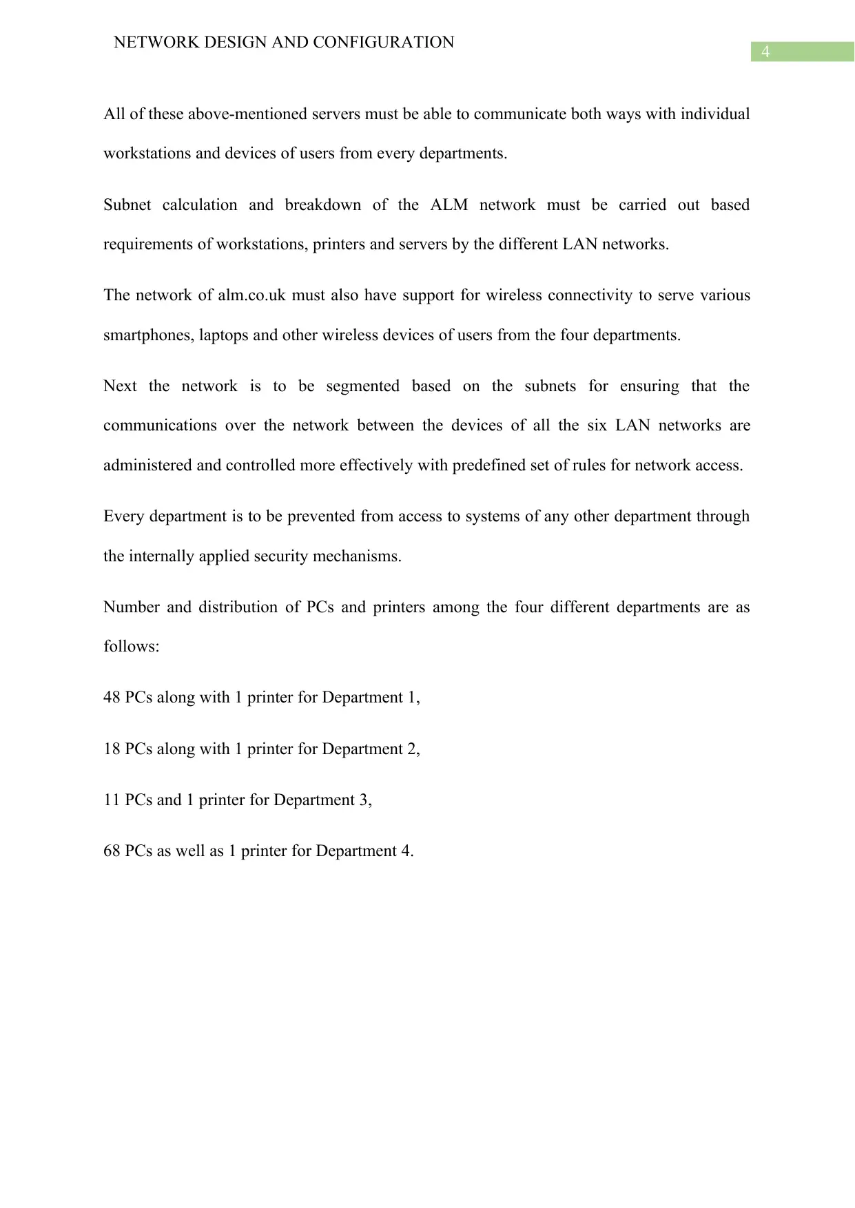
All of these above-mentioned servers must be able to communicate both ways with individual
workstations and devices of users from every departments.
Subnet calculation and breakdown of the ALM network must be carried out based
requirements of workstations, printers and servers by the different LAN networks.
The network of alm.co.uk must also have support for wireless connectivity to serve various
smartphones, laptops and other wireless devices of users from the four departments.
Next the network is to be segmented based on the subnets for ensuring that the
communications over the network between the devices of all the six LAN networks are
administered and controlled more effectively with predefined set of rules for network access.
Every department is to be prevented from access to systems of any other department through
the internally applied security mechanisms.
Number and distribution of PCs and printers among the four different departments are as
follows:
48 PCs along with 1 printer for Department 1,
18 PCs along with 1 printer for Department 2,
11 PCs and 1 printer for Department 3,
68 PCs as well as 1 printer for Department 4.
NETWORK DESIGN AND CONFIGURATION
All of these above-mentioned servers must be able to communicate both ways with individual
workstations and devices of users from every departments.
Subnet calculation and breakdown of the ALM network must be carried out based
requirements of workstations, printers and servers by the different LAN networks.
The network of alm.co.uk must also have support for wireless connectivity to serve various
smartphones, laptops and other wireless devices of users from the four departments.
Next the network is to be segmented based on the subnets for ensuring that the
communications over the network between the devices of all the six LAN networks are
administered and controlled more effectively with predefined set of rules for network access.
Every department is to be prevented from access to systems of any other department through
the internally applied security mechanisms.
Number and distribution of PCs and printers among the four different departments are as
follows:
48 PCs along with 1 printer for Department 1,
18 PCs along with 1 printer for Department 2,
11 PCs and 1 printer for Department 3,
68 PCs as well as 1 printer for Department 4.
5
NETWORK DESIGN AND CONFIGURATION
Solution
Network Design
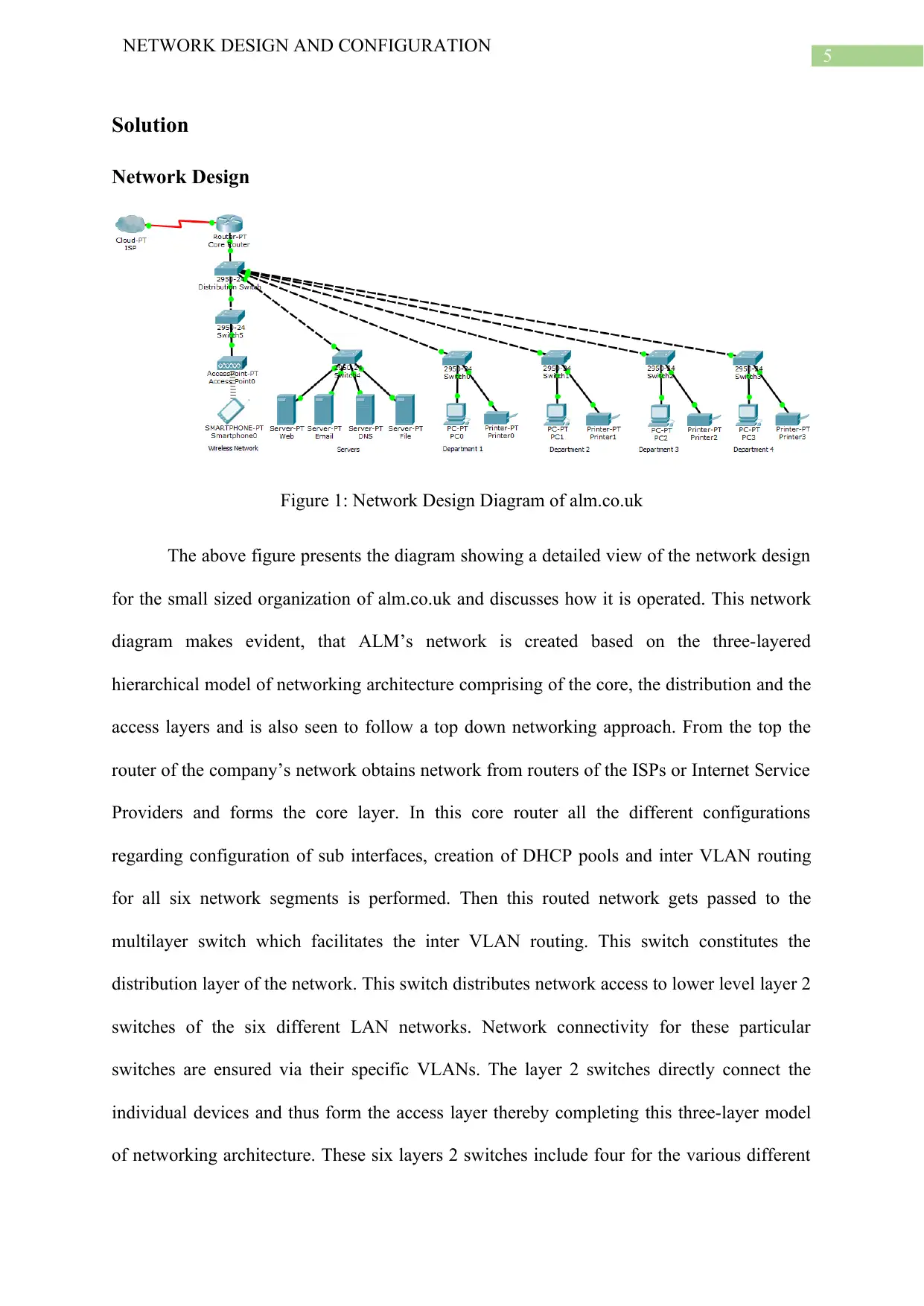
Figure 1: Network Design Diagram of alm.co.uk
The above figure presents the diagram showing a detailed view of the network design
for the small sized organization of alm.co.uk and discusses how it is operated. This network
diagram makes evident, that ALM’s network is created based on the three-layered
hierarchical model of networking architecture comprising of the core, the distribution and the
access layers and is also seen to follow a top down networking approach. From the top the
router of the company’s network obtains network from routers of the ISPs or Internet Service
Providers and forms the core layer. In this core router all the different configurations
regarding configuration of sub interfaces, creation of DHCP pools and inter VLAN routing
for all six network segments is performed. Then this routed network gets passed to the
multilayer switch which facilitates the inter VLAN routing. This switch constitutes the
distribution layer of the network. This switch distributes network access to lower level layer 2
switches of the six different LAN networks. Network connectivity for these particular
switches are ensured via their specific VLANs. The layer 2 switches directly connect the
individual devices and thus form the access layer thereby completing this three-layer model
of networking architecture. These six layers 2 switches include four for the various different
NETWORK DESIGN AND CONFIGURATION
Solution
Network Design
Figure 1: Network Design Diagram of alm.co.uk
The above figure presents the diagram showing a detailed view of the network design
for the small sized organization of alm.co.uk and discusses how it is operated. This network
diagram makes evident, that ALM’s network is created based on the three-layered
hierarchical model of networking architecture comprising of the core, the distribution and the
access layers and is also seen to follow a top down networking approach. From the top the
router of the company’s network obtains network from routers of the ISPs or Internet Service
Providers and forms the core layer. In this core router all the different configurations
regarding configuration of sub interfaces, creation of DHCP pools and inter VLAN routing
for all six network segments is performed. Then this routed network gets passed to the
multilayer switch which facilitates the inter VLAN routing. This switch constitutes the
distribution layer of the network. This switch distributes network access to lower level layer 2
switches of the six different LAN networks. Network connectivity for these particular
switches are ensured via their specific VLANs. The layer 2 switches directly connect the
individual devices and thus form the access layer thereby completing this three-layer model
of networking architecture. These six layers 2 switches include four for the various different
⊘ This is a preview!⊘
Do you want full access?
Subscribe today to unlock all pages.
Trusted by 1+ million students worldwide
6
NETWORK DESIGN AND CONFIGURATION
departments of ALM and two for the server cluster and the wireless network. There server
cluster in the network consists of four servers. They are the web, DNS, mail and the FTP
servers. The network gets segmented with VLANs for every LAN network, access between
different departments is restricted by the use of access control list or ACL list of commands.
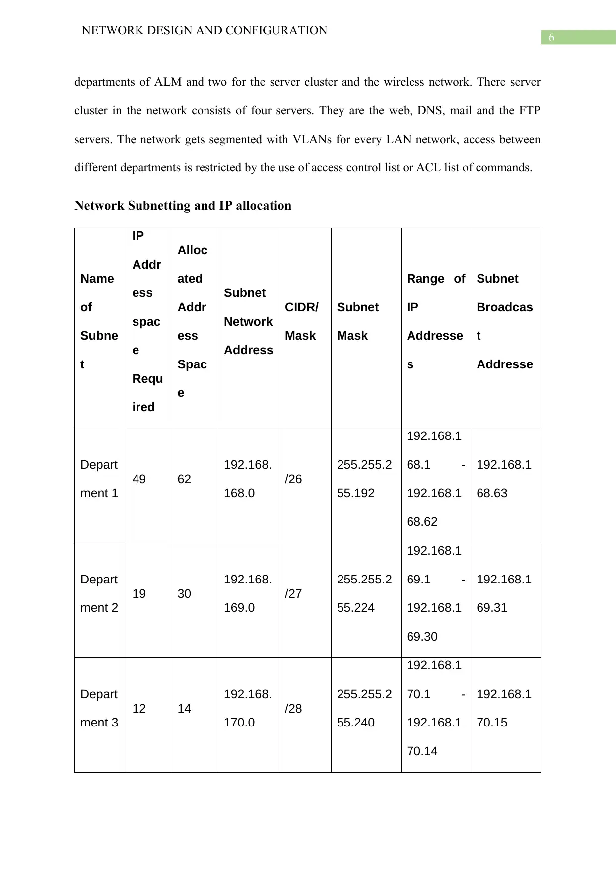
Network Subnetting and IP allocation
Name
of
Subne
t
IP
Addr
ess
spac
e
Requ
ired
Alloc
ated
Addr
ess
Spac
e
Subnet
Network
Address
CIDR/
Mask
Subnet
Mask
Range of
IP
Addresse
s
Subnet
Broadcas
t
Addresse
Depart
ment 1
49 62
192.168.
168.0
/26
255.255.2
55.192
192.168.1
68.1 -
192.168.1
68.62
192.168.1
68.63
Depart
ment 2
19 30
192.168.
169.0
/27
255.255.2
55.224
192.168.1
69.1 -
192.168.1
69.30
192.168.1
69.31
Depart
ment 3
12 14
192.168.
170.0
/28
255.255.2
55.240
192.168.1
70.1 -
192.168.1
70.14
192.168.1
70.15
NETWORK DESIGN AND CONFIGURATION
departments of ALM and two for the server cluster and the wireless network. There server
cluster in the network consists of four servers. They are the web, DNS, mail and the FTP
servers. The network gets segmented with VLANs for every LAN network, access between
different departments is restricted by the use of access control list or ACL list of commands.
Network Subnetting and IP allocation
Name
of
Subne
t
IP
Addr
ess
spac
e
Requ
ired
Alloc
ated
Addr
ess
Spac
e
Subnet
Network
Address
CIDR/
Mask
Subnet
Mask
Range of
IP
Addresse
s
Subnet
Broadcas
t
Addresse
Depart
ment 1
49 62
192.168.
168.0
/26
255.255.2
55.192
192.168.1
68.1 -
192.168.1
68.62
192.168.1
68.63
Depart
ment 2
19 30
192.168.
169.0
/27
255.255.2
55.224
192.168.1
69.1 -
192.168.1
69.30
192.168.1
69.31
Depart
ment 3
12 14
192.168.
170.0
/28
255.255.2
55.240
192.168.1
70.1 -
192.168.1
70.14
192.168.1
70.15
Paraphrase This Document
Need a fresh take? Get an instant paraphrase of this document with our AI Paraphraser
7
NETWORK DESIGN AND CONFIGURATION
Depart
ment 4
69 126
192.168.
171.0
/25
255.255.2
5.128
192.168.1
71.1 -
192.168.1
71.126
192.168.1
71.127
Server
LAN
4 6
192.168.
172.0
29
255.255.2
55.248
192.168.1
72.1 -
192.168.1
72.6
192.168.1
72.7
Wireles
s
Networ
k LAN
250 254
10.11.12
.0
/24
255.255.2
55.0
10.11.12.1
-
10.11.12.2
54
10.11.12.2
55
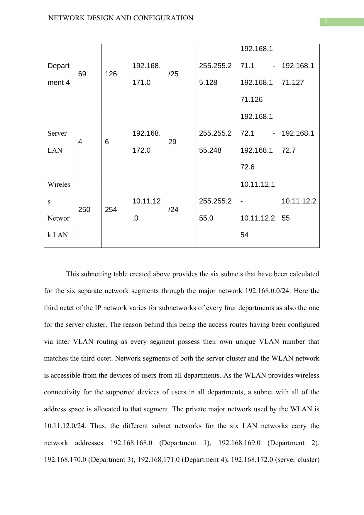
This subnetting table created above provides the six subnets that have been calculated
for the six separate network segments through the major network 192.168.0.0/24. Here the
third octet of the IP network varies for subnetworks of every four departments as also the one
for the server cluster. The reason behind this being the access routes having been configured
via inter VLAN routing as every segment possess their own unique VLAN number that
matches the third octet. Network segments of both the server cluster and the WLAN network
is accessible from the devices of users from all departments. As the WLAN provides wireless
connectivity for the supported devices of users in all departments, a subnet with all of the
address space is allocated to that segment. The private major network used by the WLAN is
10.11.12.0/24. Thus, the different subnet networks for the six LAN networks carry the
network addresses 192.168.168.0 (Department 1), 192.168.169.0 (Department 2),
192.168.170.0 (Department 3), 192.168.171.0 (Department 4), 192.168.172.0 (server cluster)
NETWORK DESIGN AND CONFIGURATION
Depart
ment 4
69 126
192.168.
171.0
/25
255.255.2
5.128
192.168.1
71.1 -
192.168.1
71.126
192.168.1
71.127
Server
LAN
4 6
192.168.
172.0
29
255.255.2
55.248
192.168.1
72.1 -
192.168.1
72.6
192.168.1
72.7
Wireles
s
Networ
k LAN
250 254
10.11.12
.0
/24
255.255.2
55.0
10.11.12.1
-
10.11.12.2
54
10.11.12.2
55
This subnetting table created above provides the six subnets that have been calculated
for the six separate network segments through the major network 192.168.0.0/24. Here the
third octet of the IP network varies for subnetworks of every four departments as also the one
for the server cluster. The reason behind this being the access routes having been configured
via inter VLAN routing as every segment possess their own unique VLAN number that
matches the third octet. Network segments of both the server cluster and the WLAN network
is accessible from the devices of users from all departments. As the WLAN provides wireless
connectivity for the supported devices of users in all departments, a subnet with all of the
address space is allocated to that segment. The private major network used by the WLAN is
10.11.12.0/24. Thus, the different subnet networks for the six LAN networks carry the
network addresses 192.168.168.0 (Department 1), 192.168.169.0 (Department 2),
192.168.170.0 (Department 3), 192.168.171.0 (Department 4), 192.168.172.0 (server cluster)
8
NETWORK DESIGN AND CONFIGURATION
and 10.11.12.0 (wireless network). Subnet masks for the six network segments are
255.255.255.192 (Department 1), 255.255.255.224 (Department 2), 255.255.255.240
(Department 3), 255.255.255.128 (Department 4), 255.255.255.248 for the (server cluster),
and 255.255.255.0 (wireless network) and the particular CIDR values for the six subnets
being /26, /27, /28, /25, /29 and /24 respectively. This only suggests that the IP addressing
scheme in use for subnetting the ALM network Classless Inter Domain Routing (CIDR).
CIDR based addressing benefits networks as opposed to traditional classful IP addressing
methods in the sense the change of the CIDR value results in smaller variations to the address
space made available for a given subnet. In this way CIDR assists in preventing waste of
available IP addresses for allocation which is prevalent in classful IP addressing. Hence small
organizations like ALM can benefits immensely from the CIDR IP addressing scheme in
saving cost to acquire or implement their network.
⊘ This is a preview!⊘
Do you want full access?
Subscribe today to unlock all pages.
Trusted by 1+ million students worldwide
9
NETWORK DESIGN AND CONFIGURATION
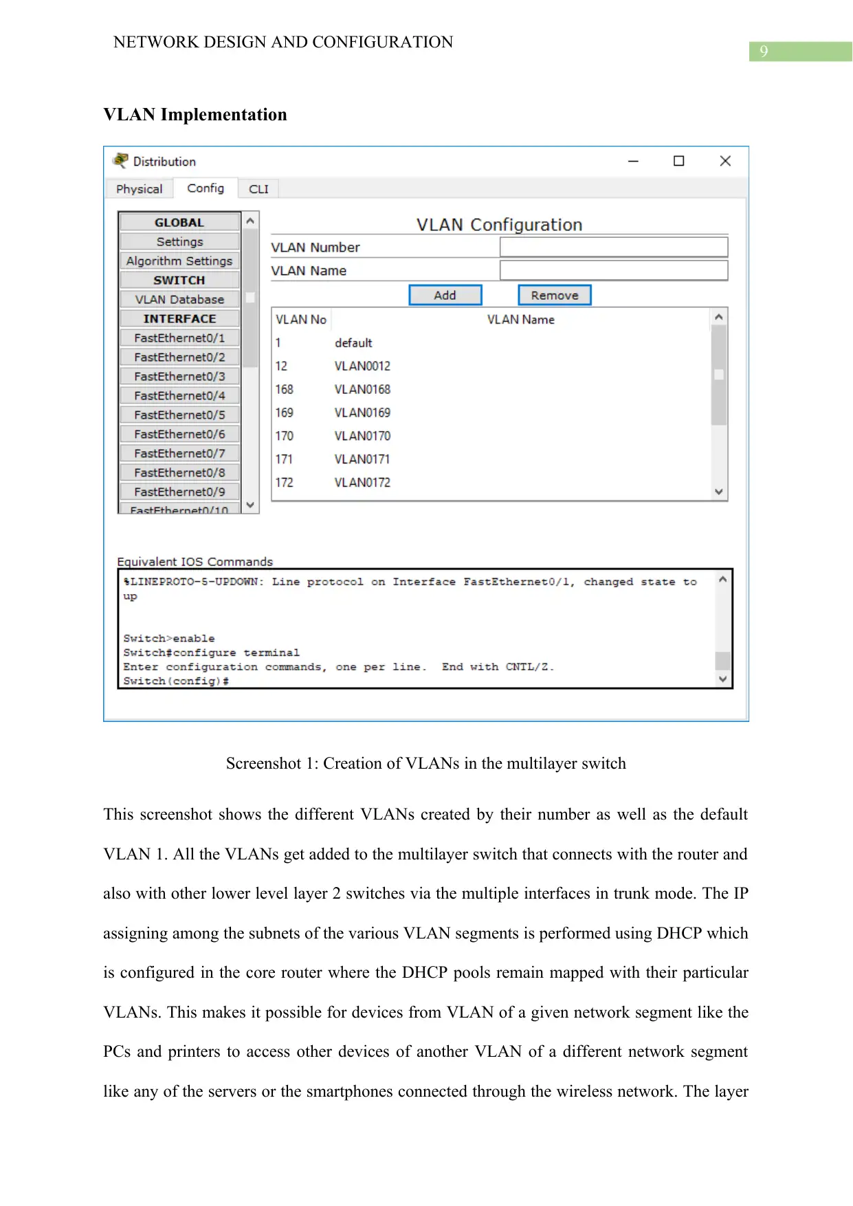
VLAN Implementation
Screenshot 1: Creation of VLANs in the multilayer switch
This screenshot shows the different VLANs created by their number as well as the default
VLAN 1. All the VLANs get added to the multilayer switch that connects with the router and
also with other lower level layer 2 switches via the multiple interfaces in trunk mode. The IP
assigning among the subnets of the various VLAN segments is performed using DHCP which
is configured in the core router where the DHCP pools remain mapped with their particular
VLANs. This makes it possible for devices from VLAN of a given network segment like the
PCs and printers to access other devices of another VLAN of a different network segment
like any of the servers or the smartphones connected through the wireless network. The layer
NETWORK DESIGN AND CONFIGURATION
VLAN Implementation
Screenshot 1: Creation of VLANs in the multilayer switch
This screenshot shows the different VLANs created by their number as well as the default
VLAN 1. All the VLANs get added to the multilayer switch that connects with the router and
also with other lower level layer 2 switches via the multiple interfaces in trunk mode. The IP
assigning among the subnets of the various VLAN segments is performed using DHCP which
is configured in the core router where the DHCP pools remain mapped with their particular
VLANs. This makes it possible for devices from VLAN of a given network segment like the
PCs and printers to access other devices of another VLAN of a different network segment
like any of the servers or the smartphones connected through the wireless network. The layer
Paraphrase This Document
Need a fresh take? Get an instant paraphrase of this document with our AI Paraphraser
10
NETWORK DESIGN AND CONFIGURATION
2 switches are connecting individual devices like PCs, smartphones and servers through the
different VLANs via respective interfaces in switchport mode access. This enables the
devices in each department in communicating with each other. The six different VLANs for
the six different network segments based on their numbers are 12 (WLAN), 168 (Department
1), 169 (Department 2), 170 (Department 3), 171 (Department 4) and 172 for the server
cluster.
VLAN Access Restrictions using Access Control List
The Access control list or ACL are the list of CLI terminal commands that have been
used to block access privileges like communication between devices of different departments.
These ACL commands can be used to impose several kinds of network restrictions on any
network that could include denying of access to HTTP servers or ping-based messages as in
echo requests and replies. The screenshot below presents the list of ICMP restrictions ACL
commands can make.
11
NETWORK DESIGN AND CONFIGURATION
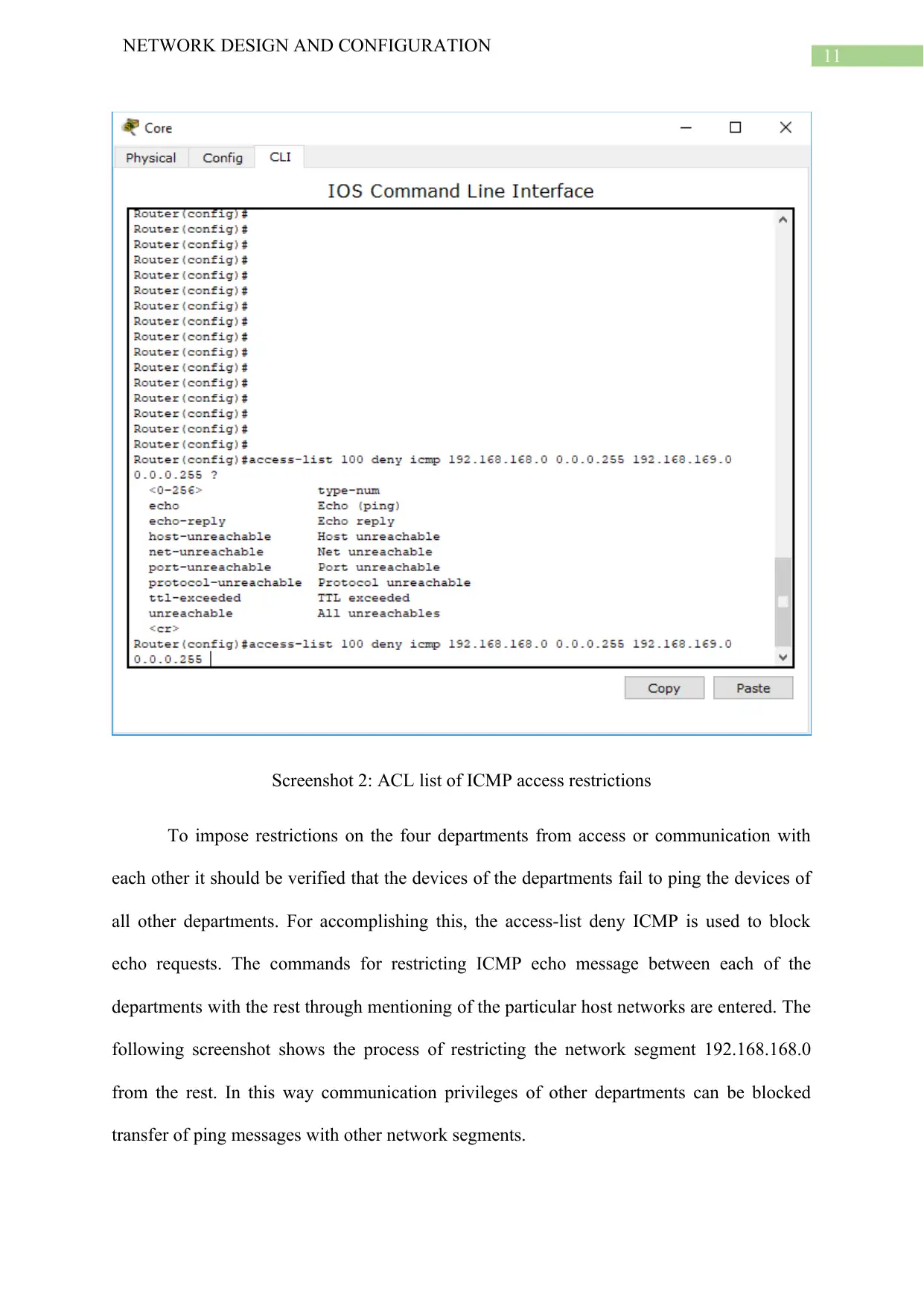
Screenshot 2: ACL list of ICMP access restrictions
To impose restrictions on the four departments from access or communication with
each other it should be verified that the devices of the departments fail to ping the devices of
all other departments. For accomplishing this, the access-list deny ICMP is used to block
echo requests. The commands for restricting ICMP echo message between each of the
departments with the rest through mentioning of the particular host networks are entered. The
following screenshot shows the process of restricting the network segment 192.168.168.0
from the rest. In this way communication privileges of other departments can be blocked
transfer of ping messages with other network segments.
NETWORK DESIGN AND CONFIGURATION
Screenshot 2: ACL list of ICMP access restrictions
To impose restrictions on the four departments from access or communication with
each other it should be verified that the devices of the departments fail to ping the devices of
all other departments. For accomplishing this, the access-list deny ICMP is used to block
echo requests. The commands for restricting ICMP echo message between each of the
departments with the rest through mentioning of the particular host networks are entered. The
following screenshot shows the process of restricting the network segment 192.168.168.0
from the rest. In this way communication privileges of other departments can be blocked
transfer of ping messages with other network segments.
⊘ This is a preview!⊘
Do you want full access?
Subscribe today to unlock all pages.
Trusted by 1+ million students worldwide
1 out of 21
Related Documents


Your All-in-One AI-Powered Toolkit for Academic Success.
+13062052269
info@desklib.com
Available 24*7 on WhatsApp / Email
![[object Object]](/_next/static/media/star-bottom.7253800d.svg)
Unlock your academic potential
Copyright © 2020–2026 A2Z Services. All Rights Reserved. Developed and managed by ZUCOL.