Analysis of Alternating Current Motors: Operation & Applications

Verified

Added on  2023/06/12

|7
|1249
|386
Report
AI Summary
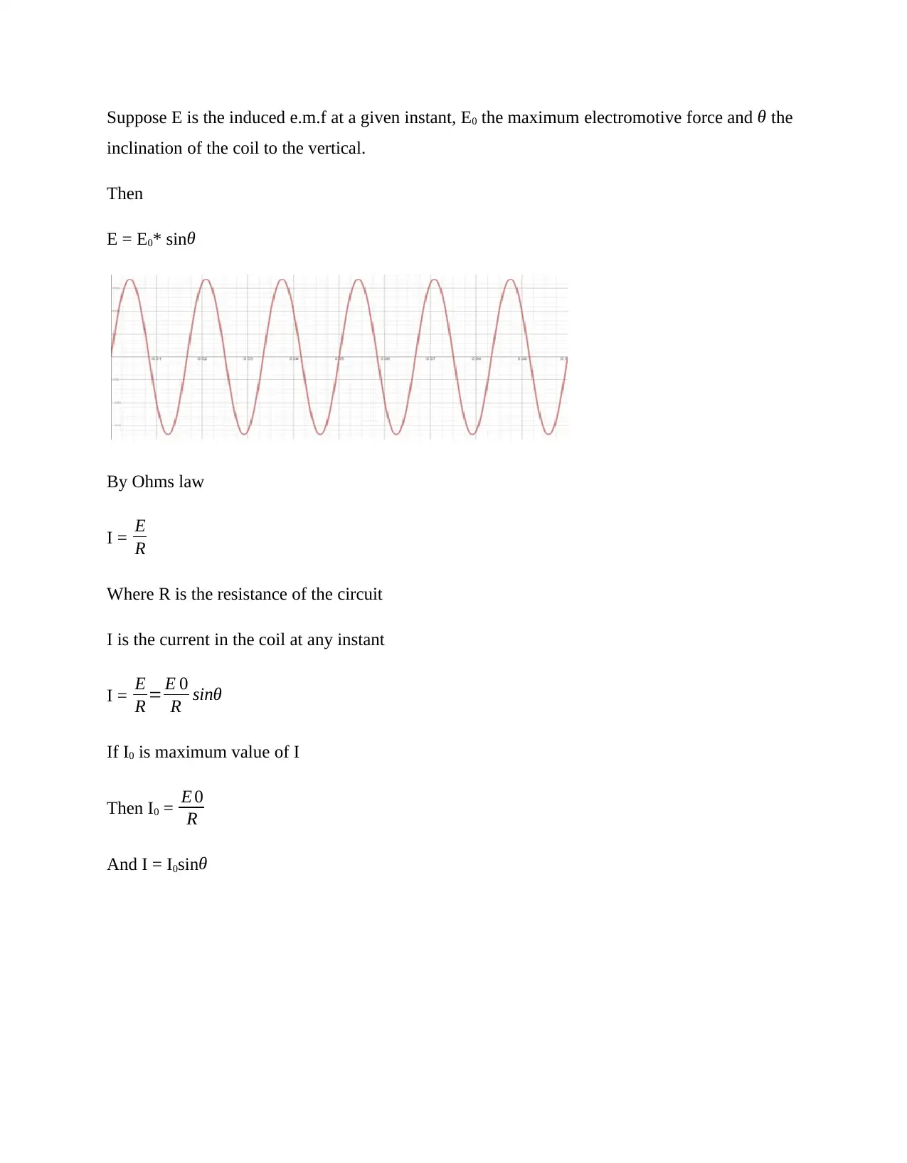
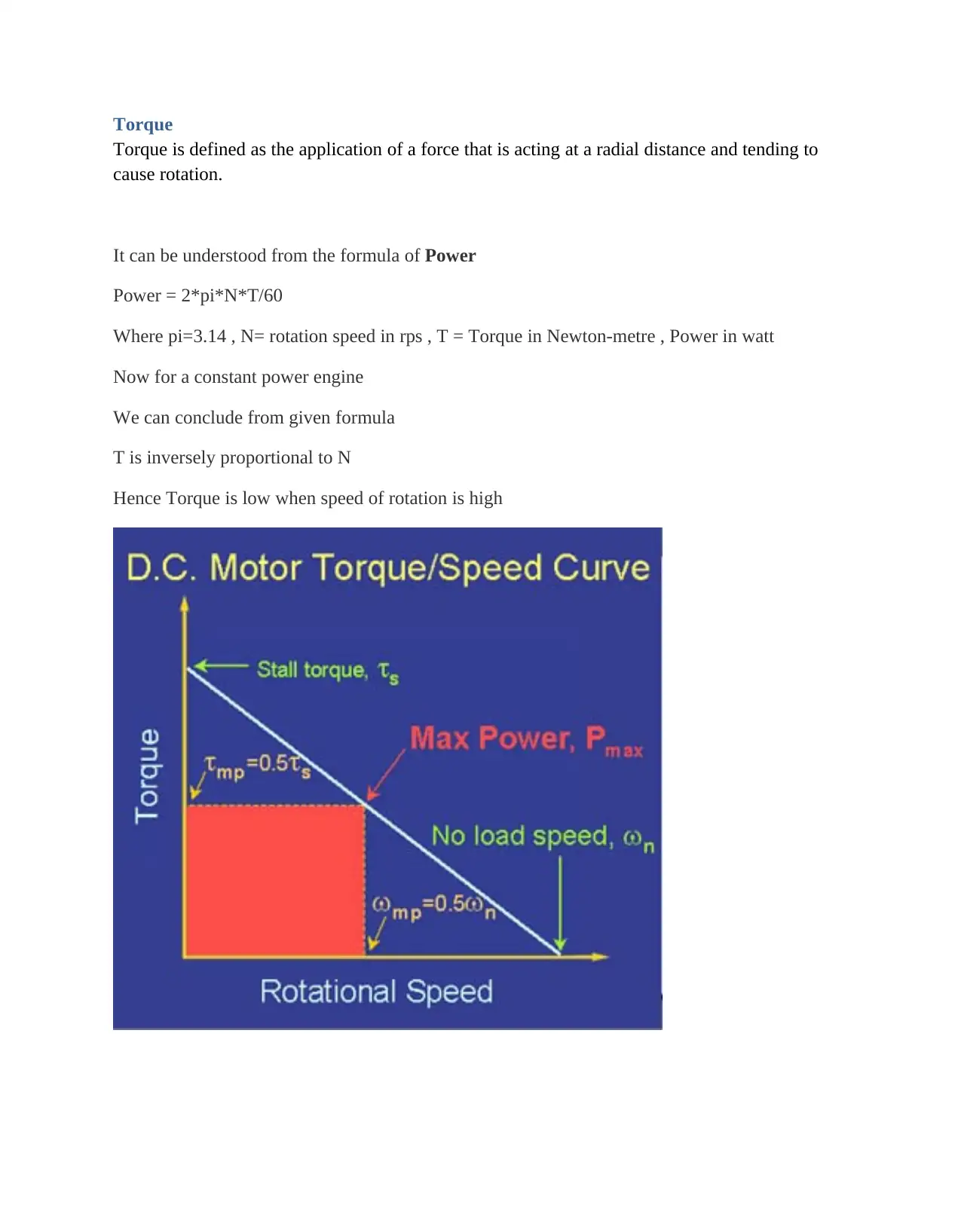
This report provides a comprehensive overview of alternating current (AC) motors, detailing their conversion of mechanical energy into electrical energy through AC generators. It explains the components and operation of an AC generator, including the role of slip rings, carbon brushes, and the induction of electromotive force (EMF) as a coil rotates within a magnetic field. The report further discusses the relationship between the angle of the coil, velocity, and induced EMF, as well as the application of Fleming's right-hand rule. It delves into the practical applications of both direct current (DC) and AC motors in automobiles, contrasting brushless DC motors with induction rotors and explaining the function of inverters in maintaining torque. The report also touches on the design of electric vehicles, including power supply and auxiliary subsystems, and classifies driving motors into switched and non-commutated engines, highlighting the advantages of permanent magnet synchronous motors. Finally, it defines torque and its inverse relationship with rotational speed in constant power engines, supported by relevant references.
Document Page
Alternating current motor
A n alternating current generator converts mechanical energy into electrical energy, an
alternating current generator consists of a rectangular coil of wire connected to slip rings. The
coil is rotated uniformly in a magnetic field. Carbon brushes which press against the slip rings
leads the induced current to an external circuit.
As the coil rotates an electromotive force is induced in both sides of the coil, since they cut the
magnetic field lines, it should be noted that no electromotive force will be induced that is parallel
to the magnetic fields lines, the electromagnetic force induced in edges of the coils depend on
their directions of motion relative to that of the magnetic field. At the instant the coil is vertical
and the edges that are perpendicular to the magnetic fields are moving to the direction that is
parallel to the magnetic and the induced electromagnetic force is zero. At the instant the coil is
horizontal and the direction of the motion of the edges is perpendicular to the magnetic field and
the induced electromotive force is maximum.
Suppose at an instant the plane of the coil is inclined at an angle θ to the vertical and the
perpendicular edges to the magnetic fields are moving with velocity v.
The components of velocity, v perpendicular and parallel to the direction of the magnetic field
are vsin θ respectively. Since e the induced electromotive force is proportion to the rate at which
the conductor cuts the magnetic flux, the induced electromotive force on the sides that are
perndicular to the magnetic field is proportion to the component of velocity of the edges
perpendicular to the magnetic field.
The induced e.m.f is thus proportion to vsin θ. Velocity v is constant and thereforce induced e.m.f
is proportion to sinθ. If maximum induced electromotive force is E0, then the induced
electromotive force E at any instant is given by E = E0* sinθ
Applying Fleming right hand rule, the induced current flows from right hand side towards the
left hand side, and the induced electromotive force will be observed to increase from zero to 900
then decreases to zero when the coil will be vertical.
tabler-icon-diamond-filled.svg

Paraphrase This Document

Need a fresh take? Get an instant paraphrase of this document with our AI Paraphraser
Document Page
Suppose E is the induced e.m.f at a given instant, E0 the maximum electromotive force and θ the
inclination of the coil to the vertical.
Then
E = E0* sinθ
By Ohms law
I = E
R
Where R is the resistance of the circuit
I is the current in the coil at any instant
I = E
R = E 0
R sinθ
If I0 is maximum value of I
Then I0 = E 0
R
And I = I0sinθ
Document Page
Application of a direct current motor and alternating current motor on the automobiles
With machines that are brushless, it will contain a rotor which includes two or more permanent
magnets that generates a direct current magnetic field, the magnetic field will enter a core which
is made up of thin stacked lamination also known as stator core, it will then interact with current
that is flowing through the winding hence producing a torque interaction (Miller, 2004) that will
be between the rotor and stator. As the rotor is rotating the polarity and magnitude of the stator
current will be continuously be varying, in order to maintain the torque to be constant and the
conversion of electrical to mechanical energy to be highly efficient, the inverter will provides the
current control.
The induction rotor has a partial similarity ranging from three sets of distributed winding that are
inserted with the stator core, their different is only on the rotor, where the induction rotor lacks
magnet, having only a stack steel lamination together with is buried peripheral conductors,
current will flow in stator windings to produce a rotating magnetic field which is equivalent to
the different between the applied electrical frequency and the rotation frequency.
An induced voltage will exist a cross the shorted structure that will be proportional to the speed
difference that exist between the rotor and electrical frequency, in line with the existence of
voltage, current will be produced within the rotor conductors that are proportional to the voltage.
The interaction of the current with the magnetic field will produce force that is a component that
result to rotor torque.
The connection of a 3-phase induction motor to a 3-phase electrical power will result to
production of torque at the outset, the motor will only start under load, unlike the brushless direct
current motor that will produce no starting torque when it is connected to a fixed frequency
utility power, until there is the presence of inverter that maintains phase in step with angular
position of the rotor.
Document Page
Electrical motor vehicles
The electric vehicle is design in a way that the engine will contain electric drive motor and a
battery unit and retaining all other components.
Figure 1: Primary propulsion system of the electric vehicle (Ottosson, 2007)
The power supply subsystem will have the following components: power supply, power
management unit, and unit energy recharge. Auxiliary subsystem consists of drive power steering,
climate control room and auxiliary power unit.
tabler-icon-diamond-filled.svg

Paraphrase This Document

Need a fresh take? Get an instant paraphrase of this document with our AI Paraphraser
Document Page
Figure 2: configuration of an electric vehicle (Ehsani, Gao, Emadi, 2010)
The electrical and hybrid vehicles having driving motors are classified mainly into two groups,
that include engines with switches and motors without commutation, Switching engines
basically uses direct current motors, this will include shunt excitation, excitations series, separate
excitation , excitation compound, and excitation permanent magnet motors.
It should be noted that DC motors switches and brushes will need to enter armature current for
their effective operations and maintenance of high speed.
Replacement of a field winding permanent magnet synchronous motor classic, with permanent
magnet synchronous motors will help remove conventional brushes, slip rings, and field copper
losses.
Document Page
Torque
Torque is defined as the application of a force that is acting at a radial distance and tending to
cause rotation.
It can be understood from the formula of Power
Power = 2*pi*N*T/60
Where pi=3.14 , N= rotation speed in rps , T = Torque in Newton-metre , Power in watt
Now for a constant power engine
We can conclude from given formula
T is inversely proportional to N
Hence Torque is low when speed of rotation is high
Document Page
Reference
Mehrdad Ehsani, Yimin Gao, Ali Emadi. Modern Electric, Hybrid Electric and Fuel Cell
Vehicles, Fundamentals, Theory and Design. Second Edition. CRC Press 2010.
John M. Miller. Propulsion Systems for Hybrid Vehicles. The Institution of Engineering and
Technology 2004.
http://lancet.mit.edu/motors/colorTS2.jpg
Victor, Matthais, Frank Greizer, Sven Bremicker, and Uwe Hübler. "Method of converting a
direct current voltage from a source of direct current voltage, more specifically from a
photovoltaic source of direct current voltage, into an alternating current voltage." U.S. Patent
7,411,802, issued August 12, 2008.
Jonas Ottosson. Energy Management and Control of Electrical Drives. Lund University 2007.
chevron_up_icon
1 out of 7
circle_padding
hide_on_mobile
zoom_out_icon
[object Object]