Comprehensive Report: Analysis and Design of Hotel Reservation System
VerifiedAdded on 2022/04/22
|33
|5006
|84
Report
AI Summary
This report presents a comprehensive analysis and design of a hotel reservation system for the "Meda Midula" hotel. It begins with an organizational analysis, examining the hotel's current manual reservation system and its drawbacks. The report then justifies the suitability of a computerized system, identifying the advantages of using a standard software development lifecycle model. The core of the report focuses on designing the data model using ER diagrams, detailing entities, attributes, relationships, and cardinalities. A data dictionary is included to clarify the data structure. Furthermore, the report designs the functional model using Data Flow Diagrams (DFDs), illustrating the system's processes, data flows, and external entities at both context and level 0 diagrams. The assignment fulfills the requirements of the Higher National Diploma in Computing & System Development, SEC4203 module, and demonstrates a strong understanding of system analysis and design principles, including data modeling, functional modeling, and the application of the software development lifecycle.
Assignment Cover Sheet
Qualification Module Number and Title
Higher National Diploma in Computing & System
Development
SEC4203
System Analysis & Designing
Student Name & No. Assessor
SAHAN WIJEBANDARA KG/HDCSE/12/25 M.G. Asanka Dinesh
Hand out date Submission Date
Assessment type
Assignment 1
Assignment 2
Duration/Length of
Assessment Type
Group Presentation: 15
mins (750 words
equivalent)
WRIT1-Coursework:
2250 words equivalent
Weighting of Assessment
100%
25 %
75%
Learner declaration
I, SAHAN WIJEBANDARA KG/HDCSE/12/25, certify that the work submitted for this assignment is
my own and research sources are fully acknowledged.
Marks Awarded
First assessor
IV marks
Agreed grade
Signature of the assessor Date
FEEDBACK FORM
Paraphrase This Document
Need a fresh take? Get an instant paraphrase of this document with our AI Paraphraser
INTERNATIONAL COLLEGE OF BUSINESS & TECHNOLOGY
Module:
Student:
Assessor:
Assignment:
Strong features of your work:
Areas for improvement:
Marks Awarded:
Coursework
Learning outcomes covered
1. Understand system designing methodologies, tools and the techniques
Module:
Student:
Assessor:
Assignment:
Strong features of your work:
Areas for improvement:
Marks Awarded:
Coursework
Learning outcomes covered
1. Understand system designing methodologies, tools and the techniques
2. Evaluate different systems development life cycle models
3. Analyze the system by using appropriate fact-finding techniques.
4. Design the analyzed system by using appropriate system design techniques.
Scenario and Tasks
Introduction
System Analysis & designing is a very important subject domain related to
Information systems. Information systems’ durability, Validity, efficiency & accuracy
depends on how well the system investigation & designing activities are accomplished during
the system development life cycle. Learning & making use of the best tools such as Entity
Relationship Diagram, Data Flow Diagram, Flowchart and Unified Modelling Language
Diagrams for aforementioned activities are very much essential for a system analyst.
Clear understand ability of Software Development Life Cycle model stages &
unique duties assigned to those enables software development team to maintain product
quality, track progress, project budget and the nature of the product, according to higher
satisfactory level. Selecting the best Software development process model for an information
system project is crucial since success or failure of the product can be decided by the process
model & its systematic approach.
When the subject domain is concerned it is always imperative to attention to be paid in
applying creativity and innovation for system designing in a manner that modern world man
kind’s requirements are supported by considering not only how their lives are further
improved with sophistication but also focusing on how does ethical and professional issues
are mitigated as much as possible.
Scenario
“Meda Midula” is a hotel consisting of 100 rooms needs to computerize their manual Hotel
Reservation System. The systems analyst who was assigned to this project has visited the
Hotel and he has gathered the following information about the system. The following text
describes his findings.
The 100 rooms available are categorized into different room types and each room type has
different rates. The number of rooms in different types and the corresponding rates are as
follows:
Room Type Room No. from/to Rate/Night;
Single 1 to 60 Rs. 1000
⊘ This is a preview!⊘
Do you want full access?
Subscribe today to unlock all pages.
Trusted by 1+ million students worldwide
Double 61 to 89 Rs. 1800
Suite 90 to 100 Rs. 5000
A Customer can reserve a room by calling the hotel receptionist. The receptionist will answer
customer’s queries regarding the room types, room rates, modes of payments available and
any discounts the customer is entitled to etc. The receptionist will then take the following
particulars from the customer, if customer wishes to proceed with the reservation.
Customer’s name, contact address, Country, Sex, Type of accommodation, the period of
stay, expected check in date.
Subsequently the receptionist will check the room availability. If a room is available, the
customer is informed about the room availability. If customer accepts the reservation, a room
number is allocated at the same time. The customer is also informed if a room is not
available. A customer can cancel the reservation at any time. It can be done by calling or by
sending a fax. The receptionist is also responsible for handling the cancellations. When the
customer checks-in at the hotel on the reserved date, the receptionist will obtain the
customers desired mode of payment. The customer may be entitled to a discount based on the
payment mode selected. The different payment modes and their discounts are as follows:
Payment Modes Discount
Cash - No discount
Traveler’s Cheque - 2% e.g. AMEX, Cooks etc.
Credit Card - 3% e.g. Diners, Master Etc.
Company - Depend upon the company (E.g. NEC 12%, IBM 10% etc.)
The Customer can checks-out from the hotel at any time by informing the receptionist. The
receptionist will immediately inform the billing Clerk to handle the billing. The details about
the Payments such as discounts given, company name, kind of traveler’s cheques used, and
credit card details etc. are preserved for any future reference.
If the customer needs to extend the stay he/she may do so by informing the receptionist.
Receptionist will check the room availability and extension is accepted if rooms are available.
Imagine that you have been assigned as a system Analyst by the e-Builders Systems
Development PLC to prepare a fully descriptive documentation comprised of Hotel
Reservation System analysis & designing information. In order to begin with user
requirement gathering & system environment analysis you are free to choose any higher
educational institute to conduct interviews & site observations. In prior commencing with
system investigation activities proper approval should be given to you by authorized officials
of the tourist category hotels that you are visiting. In order to get the approval you can
forward ICBT Campus official request letter to them.
Paraphrase This Document
Need a fresh take? Get an instant paraphrase of this document with our AI Paraphraser

General Guidelines for Students
1. With knowledge gain from the case study/Real world Scenario, analyse the facts
carefully and try to understand the association between each entity in the
environment. Also identify the data that is, needed to be stored for each entity and its
relationships. Any applicable assumptions made, should be clearly mention with
proper justification.
2. Final report should be in professional manner and with proper formatting.
3. The student needs to give priority in designing the software product of the
information system.
4. Organizational visits & information gathering can be done in both individual and
group basis which not exceeding 4 members per group.
5. Before organizational / Work site visits students are expected to obtain ICBT official
letter requesting the relevant company for conducting information gathering work
within their premises.
6. Please note that students are expected to maintain backup copies of work in different
media. Due to any hardware, software malfunctions or virus attacks, assignment
deadline will not be lifted.
Assignment 1
Group – (Viva and Document Submission)
Task
Conduct an organizational analysis and report the findings of the organization/
institution to what the information system will be implemented. Further justify
suitability of the information system for the same according to the present situation.
(LO1 & LO3 - 30 Marks)
Assignment 2 (70 Marks)
Individual – (Document Submission)
Tasks
1. Identify the advantage of using a standard software development lifecycle a model for
developing the software solution what is proposed for the organization/ institution.
(LO2- 30 Marks)
2. Design the data model of the software solution that will be implemented in the
organization / institution by considering all required data / information requirements
and explain briefly what is the best technique is to carry out data model designing of
the system. (LO4- 20 Marks)
3. Design the functional model of the system software solution that will be
implemented in the organization / institution having concerned all the features
/facilities, data collection, transitions, transfers and dissemination requirements and
explain briefly what is the best technique is to carry out functional model designing
of the system. (LO4-20 Marks)
⊘ This is a preview!⊘
Do you want full access?
Subscribe today to unlock all pages.
Trusted by 1+ million students worldwide
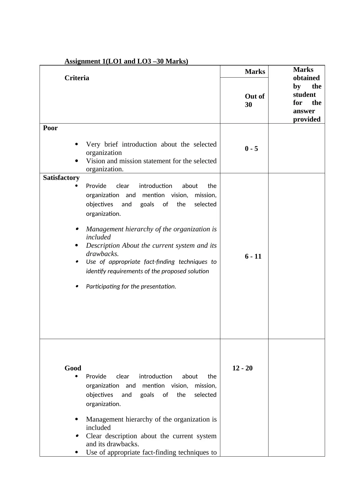
Assignment 1(LO1 and LO3 –30 Marks)
Criteria Marks Marks
obtained
by the
student
for the
answer
provided
Out of
30
Poor
Very brief introduction about the selected
organization
Vision and mission statement for the selected
organization.
0 - 5
Satisfactory
Provide clear introduction about the
organization and mention vision, mission,
objectives and goals of the selected
organization.
Management hierarchy of the organization is
included
Description About the current system and its
drawbacks.
Use of appropriate fact-finding techniques to
identify requirements of the proposed solution
Participating for the presentation.
6 - 11
Good
Provide clear introduction about the
organization and mention vision, mission,
objectives and goals of the selected
organization.
Management hierarchy of the organization is
included
Clear description about the current system
and its drawbacks.
Use of appropriate fact-finding techniques to
12 - 20
Paraphrase This Document
Need a fresh take? Get an instant paraphrase of this document with our AI Paraphraser
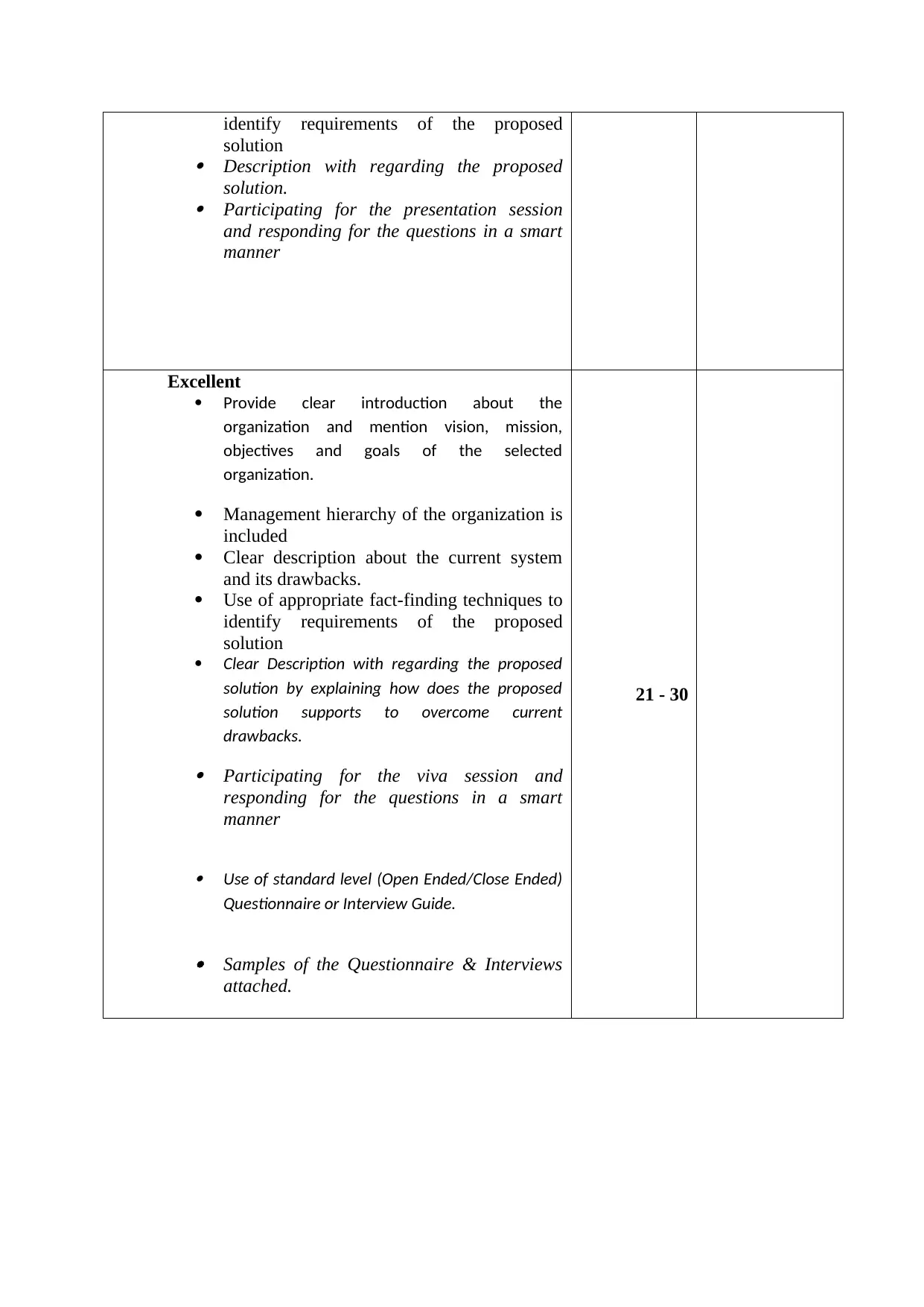
identify requirements of the proposed
solution
Description with regarding the proposed
solution.
Participating for the presentation session
and responding for the questions in a smart
manner
Excellent
Provide clear introduction about the
organization and mention vision, mission,
objectives and goals of the selected
organization.
Management hierarchy of the organization is
included
Clear description about the current system
and its drawbacks.
Use of appropriate fact-finding techniques to
identify requirements of the proposed
solution
Clear Description with regarding the proposed
solution by explaining how does the proposed
solution supports to overcome current
drawbacks.
Participating for the viva session and
responding for the questions in a smart
manner Use of standard level (Open Ended/Close Ended)
Questionnaire or Interview Guide.
Samples of the Questionnaire & Interviews
attached.
21 - 30
solution
Description with regarding the proposed
solution.
Participating for the presentation session
and responding for the questions in a smart
manner
Excellent
Provide clear introduction about the
organization and mention vision, mission,
objectives and goals of the selected
organization.
Management hierarchy of the organization is
included
Clear description about the current system
and its drawbacks.
Use of appropriate fact-finding techniques to
identify requirements of the proposed
solution
Clear Description with regarding the proposed
solution by explaining how does the proposed
solution supports to overcome current
drawbacks.
Participating for the viva session and
responding for the questions in a smart
manner Use of standard level (Open Ended/Close Ended)
Questionnaire or Interview Guide.
Samples of the Questionnaire & Interviews
attached.
21 - 30
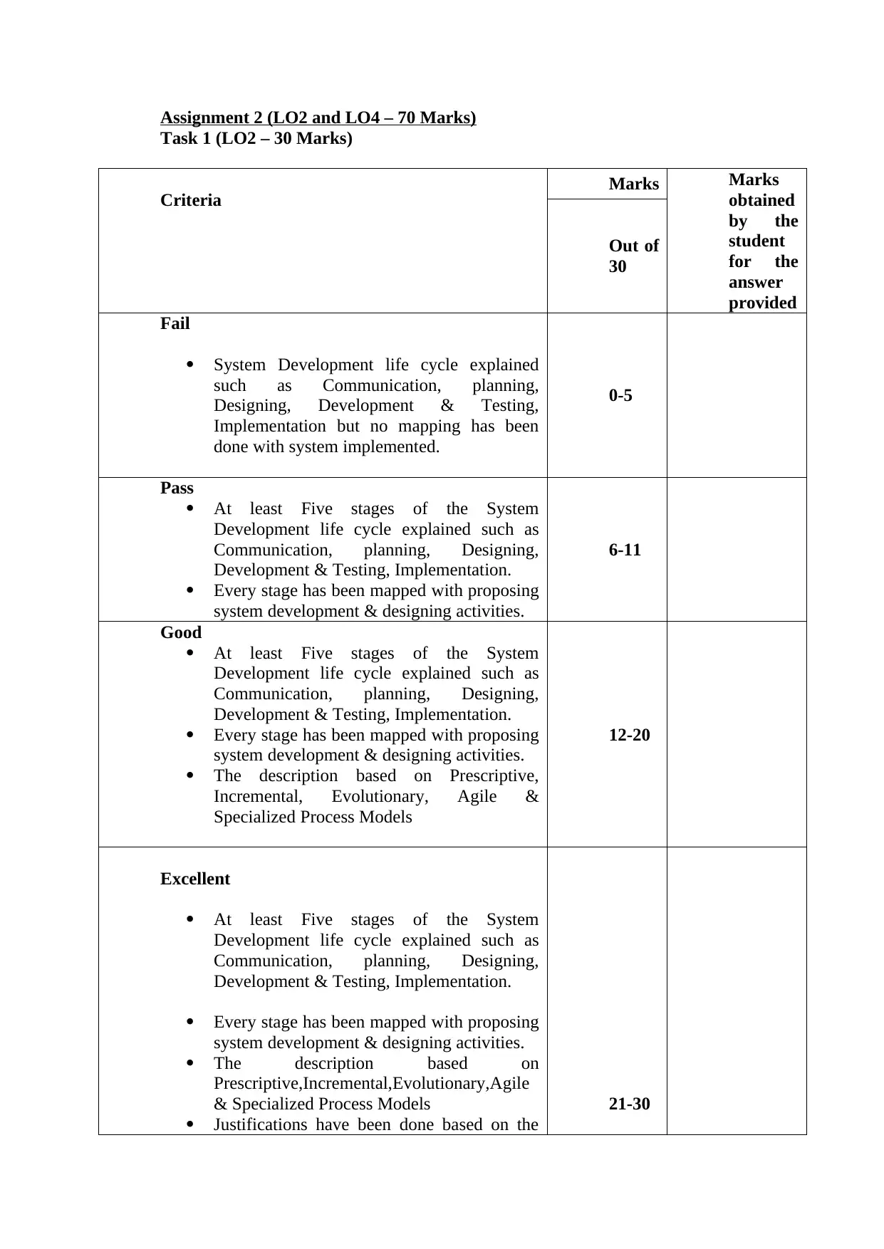
Assignment 2 (LO2 and LO4 – 70 Marks)
Task 1 (LO2 – 30 Marks)
Criteria Marks Marks
obtained
by the
student
for the
answer
provided
Out of
30
Fail
System Development life cycle explained
such as Communication, planning,
Designing, Development & Testing,
Implementation but no mapping has been
done with system implemented.
0-5
Pass
At least Five stages of the System
Development life cycle explained such as
Communication, planning, Designing,
Development & Testing, Implementation.
Every stage has been mapped with proposing
system development & designing activities.
6-11
Good
At least Five stages of the System
Development life cycle explained such as
Communication, planning, Designing,
Development & Testing, Implementation.
Every stage has been mapped with proposing
system development & designing activities.
The description based on Prescriptive,
Incremental, Evolutionary, Agile &
Specialized Process Models
12-20
Excellent
At least Five stages of the System
Development life cycle explained such as
Communication, planning, Designing,
Development & Testing, Implementation.
Every stage has been mapped with proposing
system development & designing activities.
The description based on
Prescriptive,Incremental,Evolutionary,Agile
& Specialized Process Models
Justifications have been done based on the
21-30
⊘ This is a preview!⊘
Do you want full access?
Subscribe today to unlock all pages.
Trusted by 1+ million students worldwide

qualities of the proposing system.
Paraphrase This Document
Need a fresh take? Get an instant paraphrase of this document with our AI Paraphraser
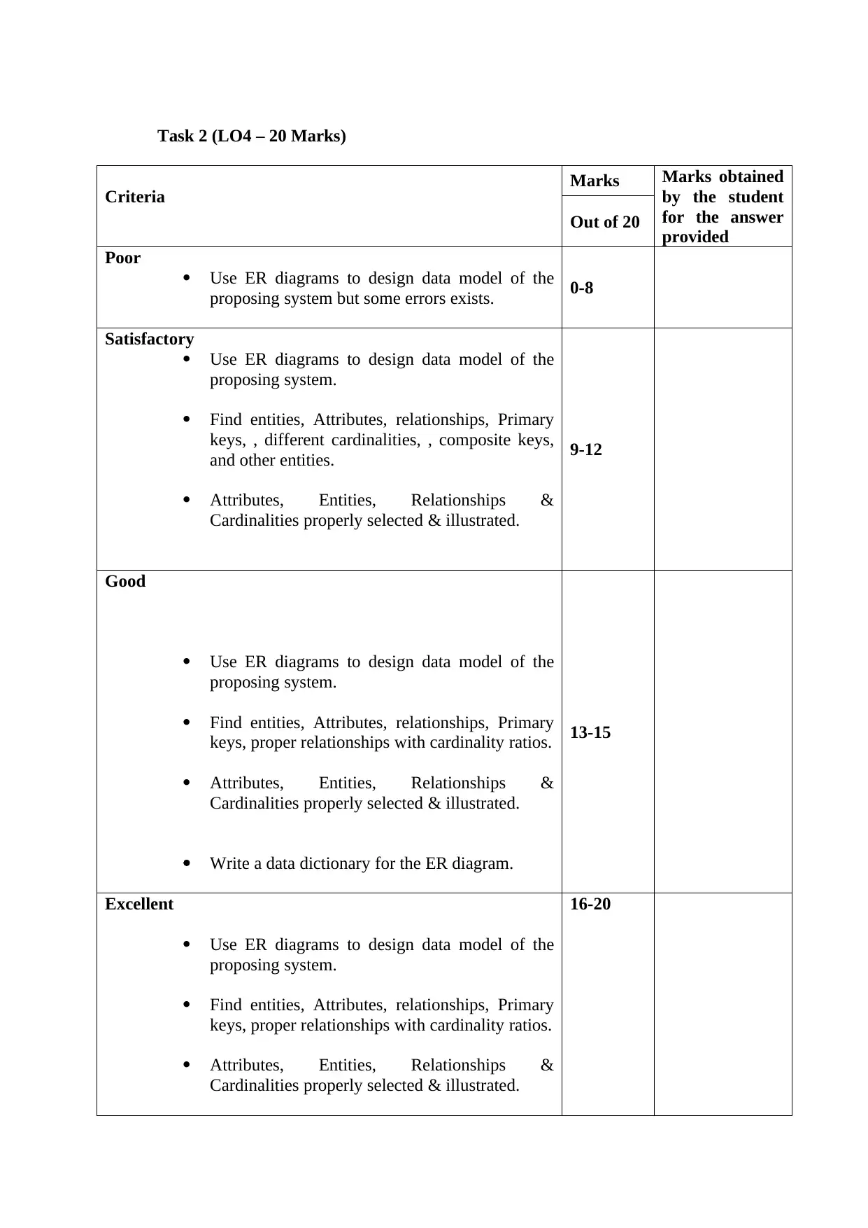
Task 2 (LO4 – 20 Marks)
Criteria Marks Marks obtained
by the student
for the answer
provided
Out of 20
Poor
Use ER diagrams to design data model of the
proposing system but some errors exists. 0-8
Satisfactory
Use ER diagrams to design data model of the
proposing system.
Find entities, Attributes, relationships, Primary
keys, , different cardinalities, , composite keys,
and other entities.
Attributes, Entities, Relationships &
Cardinalities properly selected & illustrated.
9-12
Good
Use ER diagrams to design data model of the
proposing system.
Find entities, Attributes, relationships, Primary
keys, proper relationships with cardinality ratios.
Attributes, Entities, Relationships &
Cardinalities properly selected & illustrated.
Write a data dictionary for the ER diagram.
13-15
Excellent
Use ER diagrams to design data model of the
proposing system.
Find entities, Attributes, relationships, Primary
keys, proper relationships with cardinality ratios.
Attributes, Entities, Relationships &
Cardinalities properly selected & illustrated.
16-20
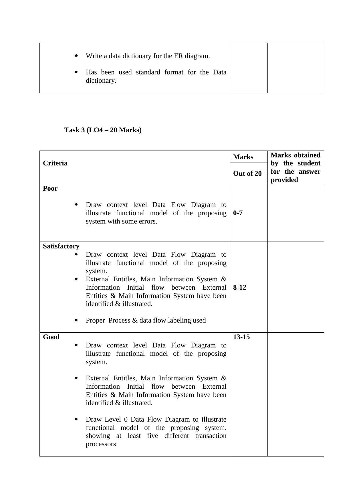
Write a data dictionary for the ER diagram.
Has been used standard format for the Data
dictionary.
Task 3 (LO4 – 20 Marks)
Criteria Marks Marks obtained
by the student
for the answer
provided
Out of 20
Poor
Draw context level Data Flow Diagram to
illustrate functional model of the proposing
system with some errors.
0-7
Satisfactory
Draw context level Data Flow Diagram to
illustrate functional model of the proposing
system.
External Entitles, Main Information System &
Information Initial flow between External
Entities & Main Information System have been
identified & illustrated.
Proper Process & data flow labeling used
8-12
Good
Draw context level Data Flow Diagram to
illustrate functional model of the proposing
system.
External Entitles, Main Information System &
Information Initial flow between External
Entities & Main Information System have been
identified & illustrated.
Draw Level 0 Data Flow Diagram to illustrate
functional model of the proposing system.
showing at least five different transaction
processors
13-15
⊘ This is a preview!⊘
Do you want full access?
Subscribe today to unlock all pages.
Trusted by 1+ million students worldwide
1 out of 33


Your All-in-One AI-Powered Toolkit for Academic Success.
+13062052269
info@desklib.com
Available 24*7 on WhatsApp / Email
![[object Object]](/_next/static/media/star-bottom.7253800d.svg)
Unlock your academic potential
Copyright © 2020–2026 A2Z Services. All Rights Reserved. Developed and managed by ZUCOL.