Software Engineering Methodologies for Real-Time System Analysis
VerifiedAdded on 2023/06/08
|9
|1730
|308
Report
AI Summary
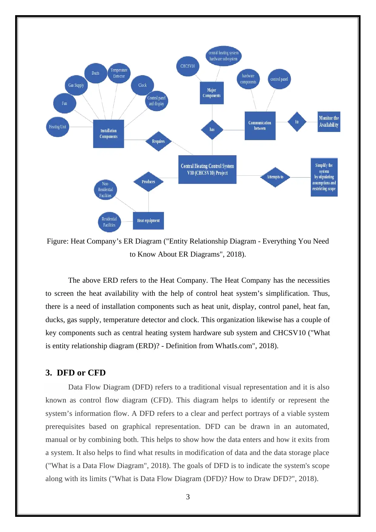
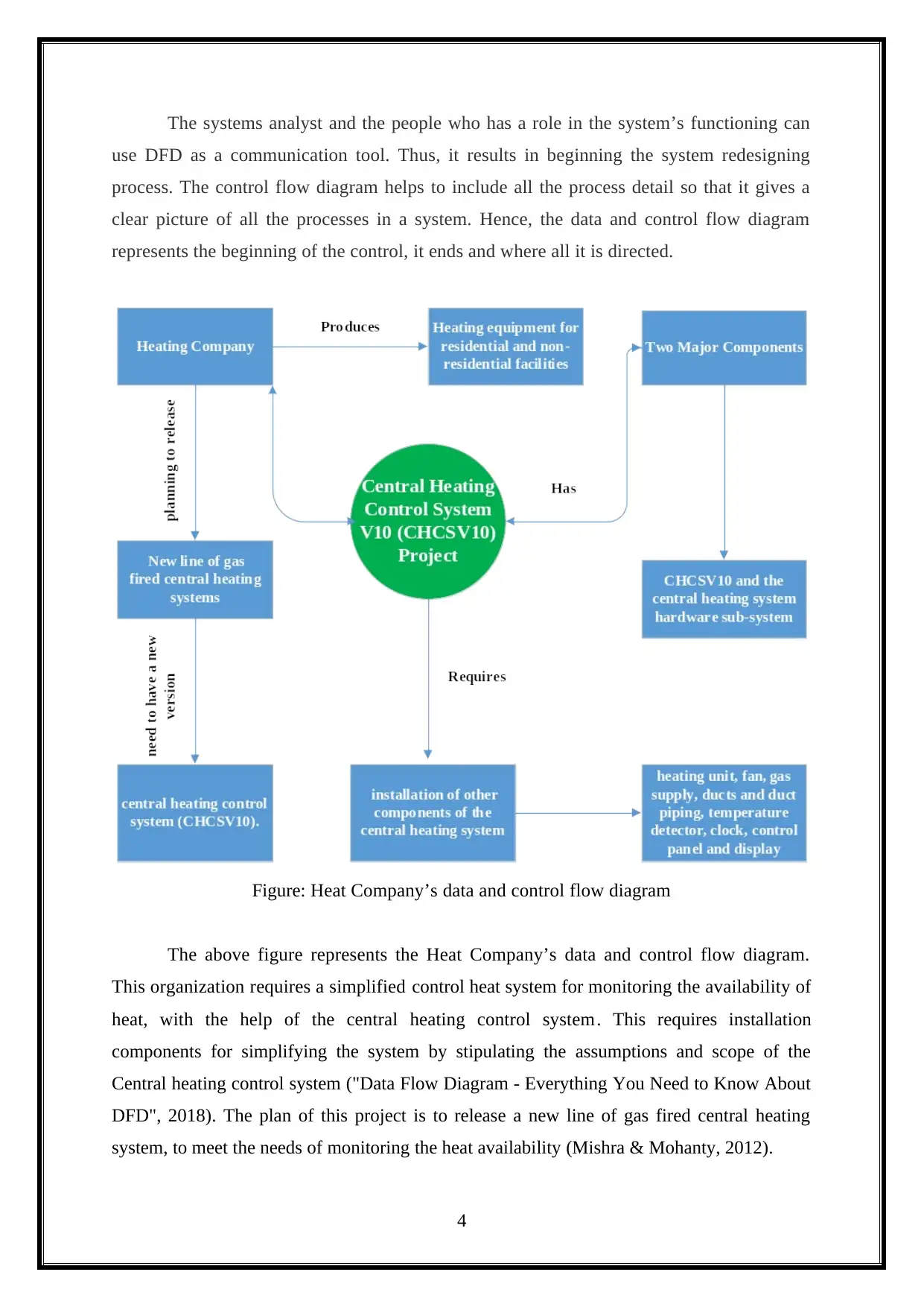
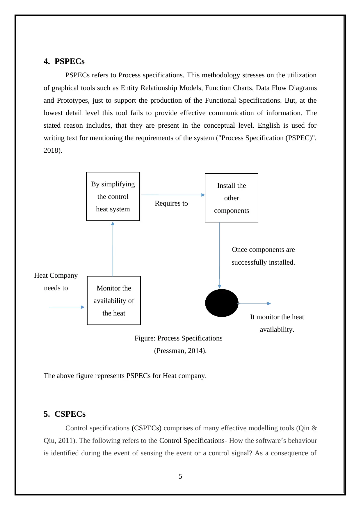
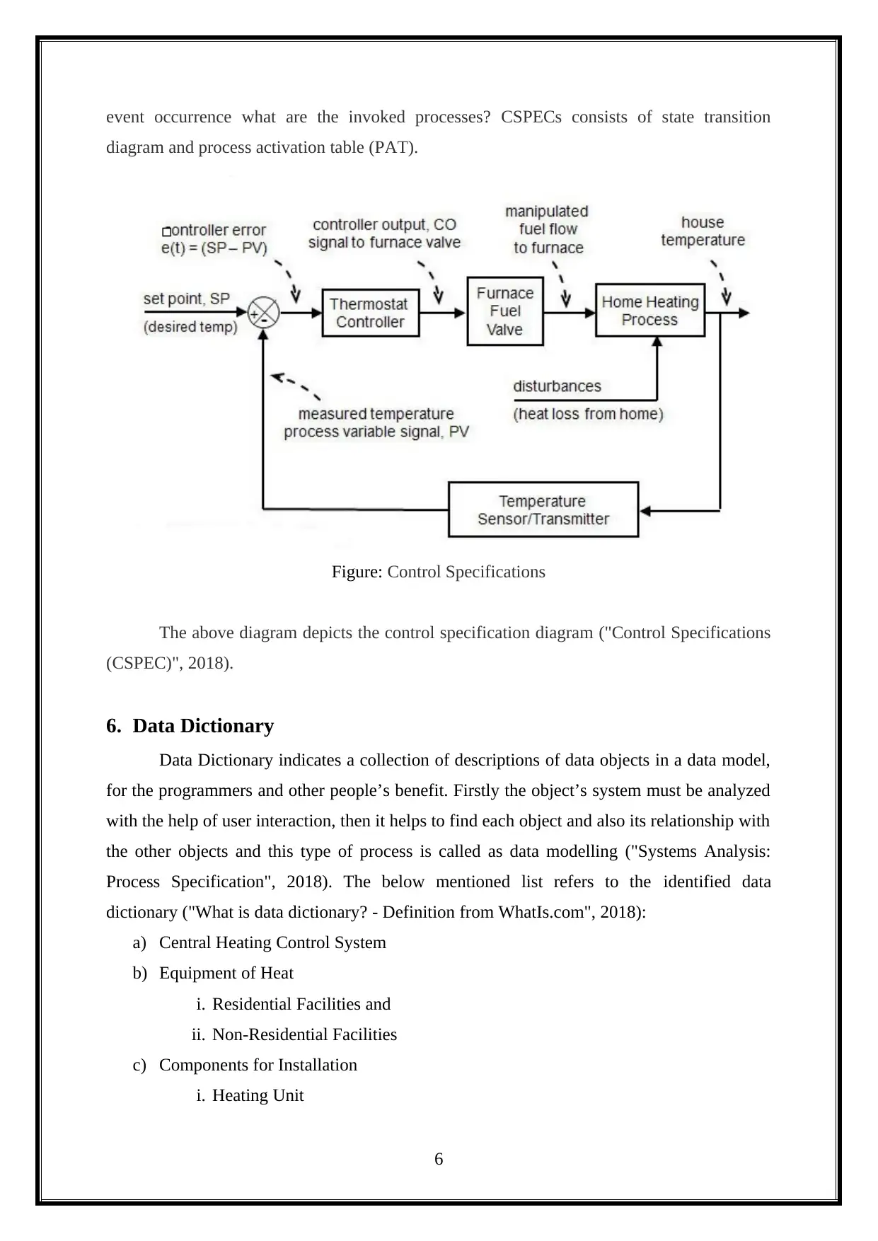
This report provides a comprehensive analysis of software engineering methodologies applied to a real-time system, specifically the CHCSV10 project for a Heat Company. It begins with an introduction outlining the project's aim to model a real-time software system for monitoring heat availability. The report then details the use of various methodologies, including Entity Relationship Diagrams (ERDs) to represent system entities and their relationships, and Data Flow Diagrams (DFDs) to illustrate the flow of data within the system. Process Specifications (PSPECs) and Control Specifications (CSPECs) are presented to define system processes and control behaviors. A Data Dictionary is included to describe data objects. The conclusion summarizes the application of these methodologies in achieving the project's objectives. The report emphasizes the importance of these methodologies in structuring and analyzing real-time systems.

SOFTWARE
ENGINEERING
METHODOLOGIES
ENGINEERING
METHODOLOGIES
Paraphrase This Document
Need a fresh take? Get an instant paraphrase of this document with our AI Paraphraser

Table of Contents
1. Introduction.........................................................................................................................2
2. ERD....................................................................................................................................2
3. DFD or CFD.......................................................................................................................3
4. PSPECs...............................................................................................................................5
5. CSPECs...............................................................................................................................5
6. Data Dictionary...................................................................................................................6
7. Conclusion..........................................................................................................................7
References..................................................................................................................................8
1

1. Introduction
This report revolves around a Heat Company and its needs. The aim of this project is
to model a real time software which is needed in CHCSV10 project. Actually, this company
wants to monitor the heat availability with the implementation of Central Heating control
V10 project. The objective of CHCSV10 project refers to producing heating equipment for
both residential facilities and for non-residential facilities. On the other hand, the actual aim
of CHCSV10 project’s plan is to release a new line of gas fired central heating system, to
meet the requirements of monitoring the heat availability, where a central heating control
system of new version is used. This project ensures to have automated facility for monitoring
all the aspects of central heating facility.
The objective of this report is to find the required facilities to achieve this facility. The
software engineering methodology will be used for completing the real time structure
analysis specification for CHCSV10 project. The External entity relationship diagram,
process specification, Control specifications, data dictionary and, data and control flow
diagrams will be studied and used to complete this project.
2. ERD
The entity relationship diagram is abbreviated as ERD and it is also called as entity
relationship model. Generally it refers to a graphical representation of information system
which depicts the relationship among the following- people, objects, places, events in a
system. This diagram helps in defining the business processes. On the other hand, it also acts
as a foundation of the relational database. Later, the relationship between the attributes and
entities is defined by the cardinality notation.
2
⊘ This is a preview!⊘
Do you want full access?
Subscribe today to unlock all pages.

Trusted by 1+ million students worldwide

Figure: Heat Company’s ER Diagram ("Entity Relationship Diagram - Everything You Need
to Know About ER Diagrams", 2018).
The above ERD refers to the Heat Company. The Heat Company has the necessities
to screen the heat availability with the help of control heat system’s simplification. Thus,
there is a need of installation components such as heat unit, display, control panel, heat fan,
ducks, gas supply, temperature detector and clock. This organization likewise has a couple of
key components such as central heating system hardware sub system and CHCSV10 ("What
is entity relationship diagram (ERD)? - Definition from WhatIs.com", 2018).
3. DFD or CFD
Data Flow Diagram (DFD) refers to a traditional visual representation and it is also
known as control flow diagram (CFD). This diagram helps to identify or represent the
system’s information flow. A DFD refers to a clear and perfect portrays of a viable system
prerequisites based on graphical representation. DFD can be drawn in an automated,
manual or by combining both. This helps to show how the data enters and how it exits from
a system. It also helps to find what results in modification of data and the data storage place
("What is a Data Flow Diagram", 2018). The goals of DFD is to indicate the system's scope
along with its limits ("What is Data Flow Diagram (DFD)? How to Draw DFD?", 2018).
3
Paraphrase This Document
Need a fresh take? Get an instant paraphrase of this document with our AI Paraphraser

The systems analyst and the people who has a role in the system’s functioning can
use DFD as a communication tool. Thus, it results in beginning the system redesigning
process. The control flow diagram helps to include all the process detail so that it gives a
clear picture of all the processes in a system. Hence, the data and control flow diagram
represents the beginning of the control, it ends and where all it is directed.
Figure: Heat Company’s data and control flow diagram
The above figure represents the Heat Company’s data and control flow diagram.
This organization requires a simplified control heat system for monitoring the availability of
heat, with the help of the central heating control system. This requires installation
components for simplifying the system by stipulating the assumptions and scope of the
Central heating control system ("Data Flow Diagram - Everything You Need to Know About
DFD", 2018). The plan of this project is to release a new line of gas fired central heating
system, to meet the needs of monitoring the heat availability (Mishra & Mohanty, 2012).
4

4. PSPECs
PSPECs refers to Process specifications. This methodology stresses on the utilization
of graphical tools such as Entity Relationship Models, Function Charts, Data Flow Diagrams
and Prototypes, just to support the production of the Functional Specifications. But, at the
lowest detail level this tool fails to provide effective communication of information. The
stated reason includes, that they are present in the conceptual level. English is used for
writing text for mentioning the requirements of the system ("Process Specification (PSPEC)",
2018).
Figure: Process Specifications
(Pressman, 2014).
The above figure represents PSPECs for Heat company.
5. CSPECs
Control specifications (CSPECs) comprises of many effective modelling tools (Qin &
Qiu, 2011). The following refers to the Control Specifications- How the software’s behaviour
is identified during the event of sensing the event or a control signal? As a consequence of
5
By simplifying
the control
heat system
Monitor the
availability of
the heat
Install the
other
components
Heat Company
needs to
Requires to
Once components are
successfully installed.
It monitor the heat
availability.
⊘ This is a preview!⊘
Do you want full access?
Subscribe today to unlock all pages.

Trusted by 1+ million students worldwide

event occurrence what are the invoked processes? CSPECs consists of state transition
diagram and process activation table (PAT).
Figure: Control Specifications
The above diagram depicts the control specification diagram ("Control Specifications
(CSPEC)", 2018).
6. Data Dictionary
Data Dictionary indicates a collection of descriptions of data objects in a data model,
for the programmers and other people’s benefit. Firstly the object’s system must be analyzed
with the help of user interaction, then it helps to find each object and also its relationship with
the other objects and this type of process is called as data modelling ("Systems Analysis:
Process Specification", 2018). The below mentioned list refers to the identified data
dictionary ("What is data dictionary? - Definition from WhatIs.com", 2018):
a) Central Heating Control System
b) Equipment of Heat
i. Residential Facilities and
ii. Non-Residential Facilities
c) Components for Installation
i. Heating Unit
6
Paraphrase This Document
Need a fresh take? Get an instant paraphrase of this document with our AI Paraphraser

ii. Gas Supply
iii. Control Panel
iv. Fan
v. Display
vi. Clock
vii. Temperature Detector
viii. Ducts
ix. Ducts Piping
d) Key components
i. Central Heating System Hardware sub system
ii. CHCEV10
e) Heat availability monitoring
f) Control system simplifying
7. Conclusion
This report effectively administered the real time software modelling needed by the
CHCSV10 project. The CHCEV10 project is undertaken by Heat Company for screening and
computerizing the heat. By executing the Central Heating control V10 project, the aim is to
monitor the accessibility of heat. The plan of CHCSV10 intends to discharge another line of
gas fired central heating system, so that effective monitoring of heat accessibility is possible
with central heating control system of a new version. It is observed that to accomplish this
facility it needs installation components for the central heating system such as the heat unit,
control panel, display, temperature detector, ducts, fan, duct piping, gas supply, and clock. In
this report, effective utilization of different software engineering methodologies are used for
finishing the real time structure analysis requirements for CHCSV10 such as External ERD,
process specifications, control specifications, data dictionary and data and control flow
diagrams. All these methodologies are studied and discussed before implementing it for this
project. It is observed that ERD provides graphical representation of information system with
relation relationship. Whereas, DFD clearly portrays the system prerequisites.
7

References
Control Specifications (CSPEC). (2018). Retrieved from
https://www.freetutes.com/systemanalysis/sa6-control-specifications.html
Data Flow Diagram - Everything You Need to Know About DFD. (2018). Retrieved from
https://www.smartdraw.com/data-flow-diagram/
Entity Relationship Diagram - Everything You Need to Know About ER Diagrams. (2018).
Retrieved from https://www.smartdraw.com/entity-relationship-diagram/
Mishra, J., & Mohanty, A. (2012). Software engineering. New Delhi, India: Dorling
Kindersley.
Pressman, R. (2014). Software engineering. New York: Mcgraw-Hill.
Process Specification (PSPEC). (2018). Retrieved from
https://www.freetutes.com/systemanalysis/sa6-process-specification.html
Qin, S., & Qiu, Z. (2011). Formal methods and software engineering. Heidelberg: Springer.
Systems Analysis: Process Specification. (2018). Retrieved from
https://it.toolbox.com/blogs/craigborysowich/systems-analysis-process-specification-
032411
What is a Data Flow Diagram. (2018). Retrieved from
https://www.lucidchart.com/pages/data-flow-diagram
What is data dictionary? - Definition from WhatIs.com. (2018). Retrieved from
https://searchmicroservices.techtarget.com/definition/data-dictionary
What is Data Flow Diagram (DFD)? How to Draw DFD?. (2018). Retrieved from
https://www.visual-paradigm.com/tutorials/data-flow-diagram-dfd.jsp
What is entity relationship diagram (ERD)? - Definition from WhatIs.com. (2018). Retrieved
from https://searchdatamanagement.techtarget.com/definition/entity-relationship-
diagram-ERD
8
⊘ This is a preview!⊘
Do you want full access?
Subscribe today to unlock all pages.

Trusted by 1+ million students worldwide
1 out of 9
Related Documents
Your All-in-One AI-Powered Toolkit for Academic Success.
+13062052269
info@desklib.com
Available 24*7 on WhatsApp / Email
Unlock your academic potential
Copyright © 2020–2025 A2Z Services. All Rights Reserved. Developed and managed by ZUCOL.


