In-Depth Analysis: Speed Control of Induction Motors & Techniques
VerifiedAdded on 2023/04/04
|28
|4011
|50
Report
AI Summary
This report provides a comprehensive analysis of speed control methods for induction motors, focusing on techniques such as varying stator voltage, stator frequency, and the voltage/frequency ratio. It begins with an introduction to induction motors, their operating principles, and synchronous speed, followed by a literature review covering equivalent circuits, torque-speed analysis, and detailed explanations of each speed control method, including circuit diagrams, graphs, and equations. The report also discusses an efficient method of speed control, supported by graphical representations and explanations, and includes a methodology section that touches on the operation of inductors and the concept of slip. The conclusion summarizes the key findings and emphasizes the importance of efficient speed control in various applications.

Electric Machines 1
ELECTRICAL MACHINES
By Name
Course
Instructor
Institution
Location
Date
ELECTRICAL MACHINES
By Name
Course
Instructor
Institution
Location
Date
Paraphrase This Document
Need a fresh take? Get an instant paraphrase of this document with our AI Paraphraser
Electric Machines 2
Speed control of Induction motor
Abstract
Several induction motors are currently being used general purposes within the surroundings to
perform different activities. Their usage range from household machines to equipment to tools
used in several industrial activities. The induction motors are slowly becoming a vital and a
source of power that cannot be dispensable within several industries. There is a wide range of
performance capabilities that are needed for these induction motors. On the speed control
segment of the induction motors, it presents a very important functional organ for the induction
motors that generally requires a lot of attention and knowledge on how to achieve. Despite being
traditionally used in the services of fixed speed, its usage has evolved over the years and is
currently being used together with variable frequency drives (VFDs) in services of variable
speed. The VFDs provide necessary opportunities of energy savings for the already existing
induction motors as well future motors in applications such as compressor load, pump and torque
centrifugal fan. This research work provides a detailed explanation of the different working
principles of the induction motors as well as general methods of speed control for these devices.
The key features for the common control methods of induction motor speeds have also been
discussed.
Electric Machines 3
Table of Contents
Abstract...................................................................................................................................................2
1. Introduction.....................................................................................................................................4
1.1. Synchronous speed......................................................................................................................4
1.2. Operating principle of the induction motor..................................................................................5
2. Literature review..............................................................................................................................6
2.1. The equivalent circuit and control of speed of induction motor...................................................6
2.2. Induction motor and their torque speed analysis........................................................................12
2.3. Analysis of various methods for speed control of induction motors..........................................15
2.3.1. By changing stator Voltage....................................................................................................15
2.3.2. By changing stator Frequency................................................................................................19
2.3.3. By changing stator Voltage/Frequency Ratio.........................................................................20
3. Efficient Method of speed control.................................................................................................21
4. Methodology..................................................................................................................................22
4.1. Operation of inductors...............................................................................................................22
4.2. Slip............................................................................................................................................23
5. Conclusion.....................................................................................................................................24
References.............................................................................................................................................26
⊘ This is a preview!⊘
Do you want full access?
Subscribe today to unlock all pages.
Trusted by 1+ million students worldwide
Electric Machines 4
1. Introduction
An induction motor basically represents a speed motor, implying that for the whole range of
loading, the change in speed for the induction motor is relatively low. It also commonly referred
to as asynchronous motor due to its ability to propel at a speed that is lower than its synchronous
speed (Barrero et al, 2012). It is an alternating current electric motor where the rotor electric
motor required in order to produce the torque is attained through electromagnetic induction from
the stator winding magnetic field. This implies that induction motors can be designed without
any electrical links to the rotor. The rotor of an induction motor can either be squirrel cage type
or the wounded type. The mostly used induction motors in most industrial drives are the 3-phase
squirrel cage type of induction motors. This is mainly due to the fact that they are more reliable,
self-starting and are generally economical.
1.1. Synchronous speed
Synchronous speed can be defined as the rotation speed for the magnetic field in any given rotary
machine. Synchronous speed often relies on the number of poles as well as the frequency of the
machine. The induction motor often operates at a speed that is generally lower than the
synchronous speed (Ben-Brahim, Tadakuma & Akdag, 2017). The rotating magnetic field is
produced in the stator. It will develop a flux in the rotor and thus enabling the rotor to rotate. As
a result of the lagging of the flux current in the rotor with the current of the flux in the stator, it
will be impossible for the rotor to attain its speed for the rotating magnetic field. This speed is
the synchronous speed.
The synchronous speed, ns for an AC motor basically represents the rate of rotation of the
magnetic field of the stator. It is given by the below expression;
Paraphrase This Document
Need a fresh take? Get an instant paraphrase of this document with our AI Paraphraser
Electric Machines 5
Where; f- the power supply frequency
p- number of magnetic poles
ns – synchronous speed for the machine
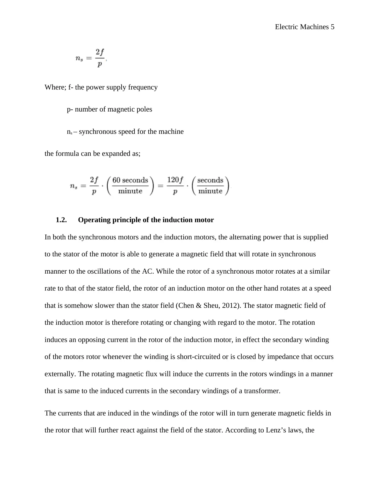
the formula can be expanded as;
1.2. Operating principle of the induction motor
In both the synchronous motors and the induction motors, the alternating power that is supplied
to the stator of the motor is able to generate a magnetic field that will rotate in synchronous
manner to the oscillations of the AC. While the rotor of a synchronous motor rotates at a similar
rate to that of the stator field, the rotor of an induction motor on the other hand rotates at a speed
that is somehow slower than the stator field (Chen & Sheu, 2012). The stator magnetic field of
the induction motor is therefore rotating or changing with regard to the motor. The rotation
induces an opposing current in the rotor of the induction motor, in effect the secondary winding
of the motors rotor whenever the winding is short-circuited or is closed by impedance that occurs
externally. The rotating magnetic flux will induce the currents in the rotors windings in a manner
that is same to the induced currents in the secondary windings of a transformer.
The currents that are induced in the windings of the rotor will in turn generate magnetic fields in
the rotor that will further react against the field of the stator. According to Lenz’s laws, the
Where; f- the power supply frequency
p- number of magnetic poles
ns – synchronous speed for the machine
the formula can be expanded as;
1.2. Operating principle of the induction motor
In both the synchronous motors and the induction motors, the alternating power that is supplied
to the stator of the motor is able to generate a magnetic field that will rotate in synchronous
manner to the oscillations of the AC. While the rotor of a synchronous motor rotates at a similar
rate to that of the stator field, the rotor of an induction motor on the other hand rotates at a speed
that is somehow slower than the stator field (Chen & Sheu, 2012). The stator magnetic field of
the induction motor is therefore rotating or changing with regard to the motor. The rotation
induces an opposing current in the rotor of the induction motor, in effect the secondary winding
of the motors rotor whenever the winding is short-circuited or is closed by impedance that occurs
externally. The rotating magnetic flux will induce the currents in the rotors windings in a manner
that is same to the induced currents in the secondary windings of a transformer.
The currents that are induced in the windings of the rotor will in turn generate magnetic fields in
the rotor that will further react against the field of the stator. According to Lenz’s laws, the
Electric Machines 6
magnetic field direction that is developed will exist in such a way that it opposes current change
through the windings of the rotor. What causes the induced current in the windings of the rotor is
the stator magnetic field that is rotating. In order to oppose the change in rotor winding currents,
the rotor will begin to rotate in the direction of the magnetic field for the rotating stator (Feng,
Liu & Huang, 2014). The rotor will continue to accelerate up to a point where the magnitude of
the torque and the induced rotor current will balance to the mechanical load that is applied to the
rotor rotation. Given that the rotation at a synchronous speed will lead to no induced current of
the rotor, the operation of the induction motor will always be at a speed that is lower than the
synchronous speed. The slip or difference between the synchronous and the actual sped ranges
from about 0.5% to 5.0%. This is always for the standard design B torque induction motors
curves. Induction motor have an essential character of being solely developed by the process of
induction and not being excited independently as in DC or synchronous machines or even being
self-magnetized as in the case of magnetic motors that are permanent (Garces, 2010).
2. Literature review
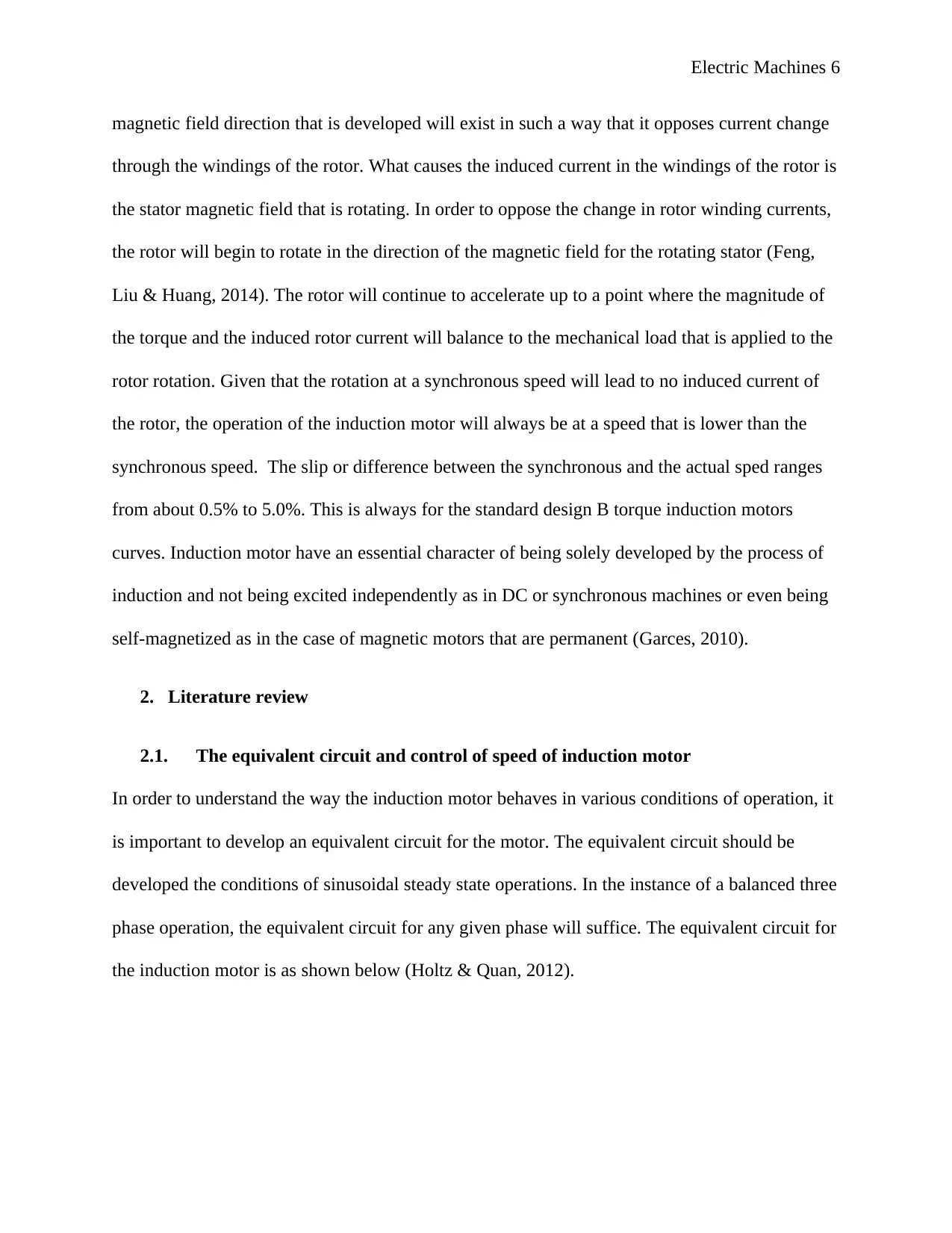
2.1. The equivalent circuit and control of speed of induction motor
In order to understand the way the induction motor behaves in various conditions of operation, it
is important to develop an equivalent circuit for the motor. The equivalent circuit should be
developed the conditions of sinusoidal steady state operations. In the instance of a balanced three
phase operation, the equivalent circuit for any given phase will suffice. The equivalent circuit for
the induction motor is as shown below (Holtz & Quan, 2012).
magnetic field direction that is developed will exist in such a way that it opposes current change
through the windings of the rotor. What causes the induced current in the windings of the rotor is
the stator magnetic field that is rotating. In order to oppose the change in rotor winding currents,
the rotor will begin to rotate in the direction of the magnetic field for the rotating stator (Feng,
Liu & Huang, 2014). The rotor will continue to accelerate up to a point where the magnitude of
the torque and the induced rotor current will balance to the mechanical load that is applied to the
rotor rotation. Given that the rotation at a synchronous speed will lead to no induced current of
the rotor, the operation of the induction motor will always be at a speed that is lower than the
synchronous speed. The slip or difference between the synchronous and the actual sped ranges
from about 0.5% to 5.0%. This is always for the standard design B torque induction motors
curves. Induction motor have an essential character of being solely developed by the process of
induction and not being excited independently as in DC or synchronous machines or even being
self-magnetized as in the case of magnetic motors that are permanent (Garces, 2010).
2. Literature review
2.1. The equivalent circuit and control of speed of induction motor
In order to understand the way the induction motor behaves in various conditions of operation, it
is important to develop an equivalent circuit for the motor. The equivalent circuit should be
developed the conditions of sinusoidal steady state operations. In the instance of a balanced three
phase operation, the equivalent circuit for any given phase will suffice. The equivalent circuit for
the induction motor is as shown below (Holtz & Quan, 2012).
⊘ This is a preview!⊘
Do you want full access?
Subscribe today to unlock all pages.
Trusted by 1+ million students worldwide
Electric Machines 7
Figure 1: equivalent circuit for the induction motor (Kim et al, 2011)
The current that is drawn by the circuit from the per-phase induction motor equivalent circuit is
given as below;
The air gap power is also expressed as below;
Mechanical output power is expressed by;
The mechanical torque is therefore given by the following equation;
Paraphrase This Document
Need a fresh take? Get an instant paraphrase of this document with our AI Paraphraser

Electric Machines 8
A plot graph of the torque in relation to the speed or slip achieves a torque- speed feature for the
motor.
A plot graph of the torque in relation to the speed or slip achieves a torque- speed feature for the
motor.
Electric Machines 9
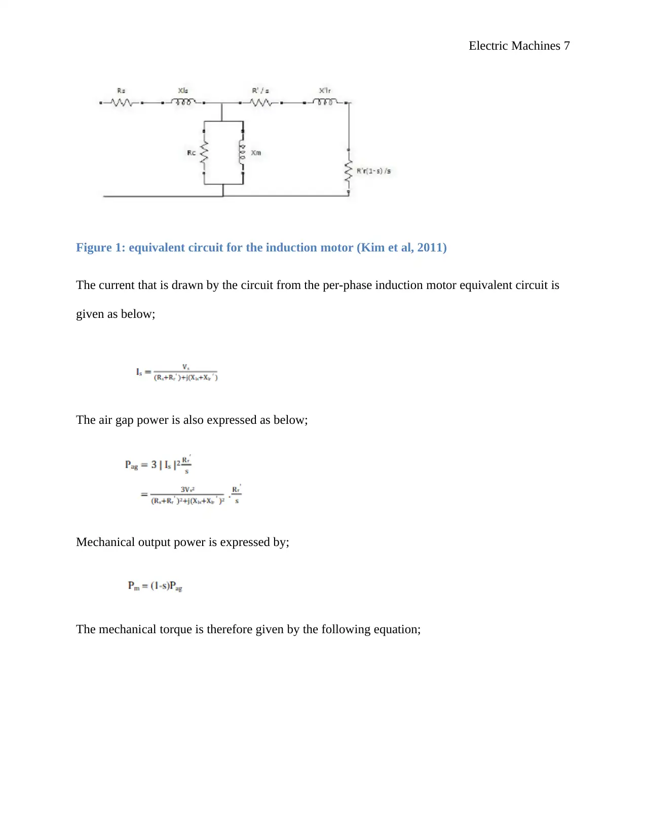
Figure 2: torque speed curve for variable voltage (Kim et al, 2011)
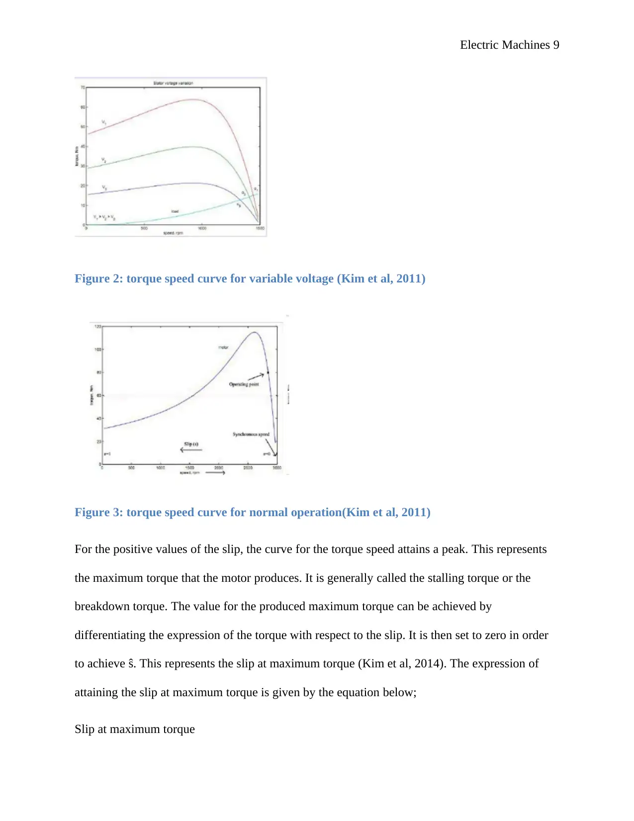
Figure 3: torque speed curve for normal operation(Kim et al, 2011)
For the positive values of the slip, the curve for the torque speed attains a peak. This represents
the maximum torque that the motor produces. It is generally called the stalling torque or the
breakdown torque. The value for the produced maximum torque can be achieved by
differentiating the expression of the torque with respect to the slip. It is then set to zero in order
to achieve ŝ. This represents the slip at maximum torque (Kim et al, 2014). The expression of
attaining the slip at maximum torque is given by the equation below;
Slip at maximum torque
Figure 2: torque speed curve for variable voltage (Kim et al, 2011)
Figure 3: torque speed curve for normal operation(Kim et al, 2011)
For the positive values of the slip, the curve for the torque speed attains a peak. This represents
the maximum torque that the motor produces. It is generally called the stalling torque or the
breakdown torque. The value for the produced maximum torque can be achieved by
differentiating the expression of the torque with respect to the slip. It is then set to zero in order
to achieve ŝ. This represents the slip at maximum torque (Kim et al, 2014). The expression of
attaining the slip at maximum torque is given by the equation below;
Slip at maximum torque
⊘ This is a preview!⊘
Do you want full access?
Subscribe today to unlock all pages.
Trusted by 1+ million students worldwide
Electric Machines 10
Maximum torque
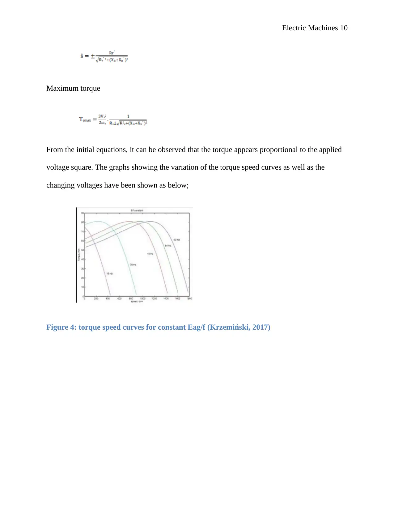
From the initial equations, it can be observed that the torque appears proportional to the applied
voltage square. The graphs showing the variation of the torque speed curves as well as the
changing voltages have been shown as below;
Figure 4: torque speed curves for constant Eag/f (Krzemiński, 2017)
Maximum torque
From the initial equations, it can be observed that the torque appears proportional to the applied
voltage square. The graphs showing the variation of the torque speed curves as well as the
changing voltages have been shown as below;
Figure 4: torque speed curves for constant Eag/f (Krzemiński, 2017)
Paraphrase This Document
Need a fresh take? Get an instant paraphrase of this document with our AI Paraphraser
Electric Machines 11
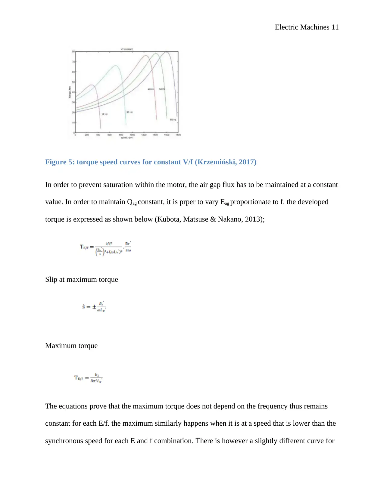
Figure 5: torque speed curves for constant V/f (Krzemiński, 2017)
In order to prevent saturation within the motor, the air gap flux has to be maintained at a constant
value. In order to maintain Qag constant, it is prper to vary Eag proportionate to f. the developed
torque is expressed as shown below (Kubota, Matsuse & Nakano, 2013);
Slip at maximum torque
Maximum torque
The equations prove that the maximum torque does not depend on the frequency thus remains
constant for each E/f. the maximum similarly happens when it is at a speed that is lower than the
synchronous speed for each E and f combination. There is however a slightly different curve for
Electric Machines 12
constant V/f. this implies that for any fixed V, the E is changed with the operating slips hence the
maximum torque is reduced (Lascu, Boldea & Blaabjerg, 2010).
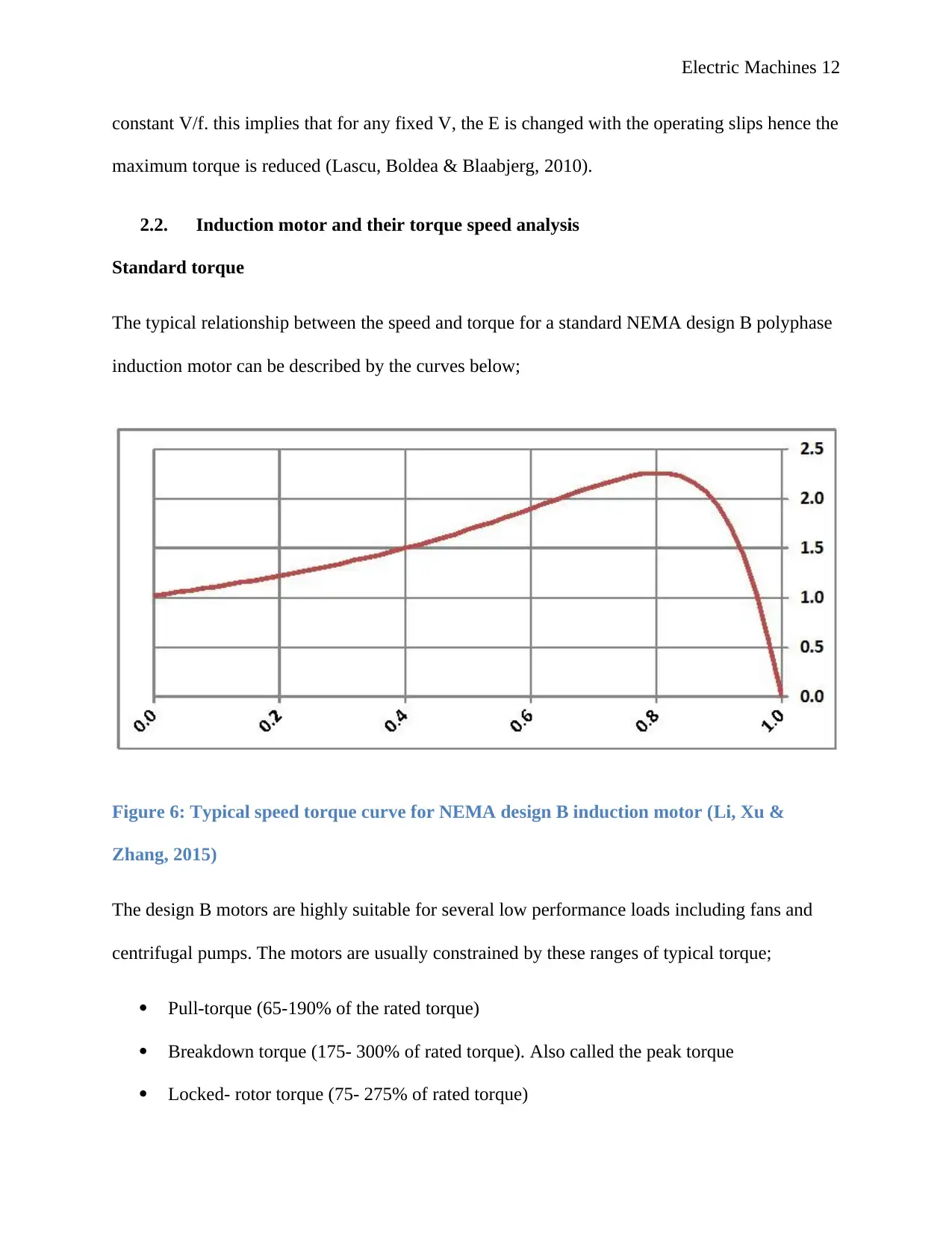
2.2. Induction motor and their torque speed analysis
Standard torque
The typical relationship between the speed and torque for a standard NEMA design B polyphase
induction motor can be described by the curves below;
Figure 6: Typical speed torque curve for NEMA design B induction motor (Li, Xu &
Zhang, 2015)
The design B motors are highly suitable for several low performance loads including fans and
centrifugal pumps. The motors are usually constrained by these ranges of typical torque;
Pull-torque (65-190% of the rated torque)
Breakdown torque (175- 300% of rated torque). Also called the peak torque
Locked- rotor torque (75- 275% of rated torque)
constant V/f. this implies that for any fixed V, the E is changed with the operating slips hence the
maximum torque is reduced (Lascu, Boldea & Blaabjerg, 2010).
2.2. Induction motor and their torque speed analysis
Standard torque
The typical relationship between the speed and torque for a standard NEMA design B polyphase
induction motor can be described by the curves below;
Figure 6: Typical speed torque curve for NEMA design B induction motor (Li, Xu &
Zhang, 2015)
The design B motors are highly suitable for several low performance loads including fans and
centrifugal pumps. The motors are usually constrained by these ranges of typical torque;
Pull-torque (65-190% of the rated torque)
Breakdown torque (175- 300% of rated torque). Also called the peak torque
Locked- rotor torque (75- 275% of rated torque)
⊘ This is a preview!⊘
Do you want full access?
Subscribe today to unlock all pages.
Trusted by 1+ million students worldwide
1 out of 28
Related Documents


Your All-in-One AI-Powered Toolkit for Academic Success.
+13062052269
info@desklib.com
Available 24*7 on WhatsApp / Email
![[object Object]](/_next/static/media/star-bottom.7253800d.svg)
Unlock your academic potential
Copyright © 2020–2026 A2Z Services. All Rights Reserved. Developed and managed by ZUCOL.