Analysis of Prestressed Concrete Box Girder Bridge using ANSYS
VerifiedAdded on 2023/04/11
|21
|4159
|289
Report
AI Summary
This report presents a finite element analysis of a prestressed concrete box girder bridge using ANSYS software. The study investigates the structural behavior of a box girder section, with and without prestressing forces, under IRC 006-2014 Class A loading conditions. The methodology involves creating a detailed FEA model based on ASBI Type 1 segmental box girders, analyzing deflection and stresses, and converting external tendon effects into equivalent nodal loads. The report includes a literature review, material properties, and a discussion of the finite element modeling process, meshing, and numerical results, concluding with key findings and acknowledgements.
Table of Contents
Introduction.................................................................................................................................................2
2. Literature review.....................................................................................................................................2
3. Materials And Properties.........................................................................................................................3
4. Methodology..........................................................................................................................................3
4.1. Finite element modelling..................................................................................................................3
4.1.1. Formulation of model................................................................................................................3
4. Technique................................................................................................................................................5
4.1. Limited component demonstrating..................................................................................................5
4.1.1. Definition of model....................................................................................................................5
4.1.2. Loading pattern.........................................................................................................................5
5. Fundamentals..........................................................................................................................................7
6. NUMERICAL ANALYSIS BY USING ANSYS..................................................................................................7
6.1 Basic strides of limited component investigation:.............................................................................7
6.2 Numerical Approach for Transverse Vibration of Fixed Free Beam:..................................................7
6.3 Portrayal of the limited component technique:................................................................................8
6.3 Imperative highlights of limited component strategy coming up next are the fundamental
highlights of the limited component technique:.....................................................................................8
6.5 FEA Results.......................................................................................................................................8
7. Meshing...................................................................................................................................................9
8. Overall Results.........................................................................................................................................9
9. CONCLUSION.........................................................................................................................................10
10. ACKNOWLEDGEMENTS........................................................................................................................11
11. Bibliography.........................................................................................................................................11
Paraphrase This Document
Need a fresh take? Get an instant paraphrase of this document with our AI Paraphraser
Introduction
Concrete is the most widely used material in construction industry. But sometimes concrete
fails to serve its purpose in structures and so prestressing technique is introduced. A
prestressed concrete structure is different from a conventional reinforced cement concrete
structure due to the application of an initial load on the structure prior to its use.
Prestressing is the introduction of a compressive force to the concrete to counteract the
stresses that will result from applied loads. Pre tensioning and post tensioning are two methods
of introducing prestressing to a concrete. Post tensioning is the process of acquainting
compressive force to the concrete after the concrete is casted. This is done by placing high
tensile steel PC Strand tendons in a desired profile. Then the tendons are stressed and locked
with anchors. Post tensioning is usually carried out at a project site. Post tensioning is getting
popular in civil constructions, example are roads, bridges, railways, tunnels, dams,
containment tanks, reservoirs, underground constructions, foundations, buildings, industrial
facilities, air & sea ports, special structures or any form of prestressed concrete structures
etc. As mentioned in above examples prestressing is suitable for bridges, so it is required to
analyse and design for the same. Box girder bridges are widely used now-a-days for
construction of bridges efficiently and economically. In this paper an attempt is made to
analyse a box girder section with and without prestressing force. The section so choose is ASBI
1800mm deep Type 1 segmental box girders of 9m width. Loadings on the girder so
considered are as per the IRC 006-2014 code i.e., moving loads class considered is Class „A‟.
To analyse manually a box girder is itself is a challenge, so to ease the analysis process finite
element approach is considered to be fair. The box girder is modelled in finite element
software ANSYS Workbench and analysed for deflection and stresses. The effects of
external tendons are converted into equivalent nodal loads.
2. Literature review
1. In the live load results of prestressed girder the distribution factors from the AASHTO LRFD
specifications were significantly higher than those calculated from the calibrated FEM. It was
also 2. Concluded that the parapets affected the magnitude of the distribution factors. By
excluding the parapets from the model, the exterior girder had distribution factors that where 20
to 25% lower than those when the parapets were included. 3. The loss of prestress during the life
span will be the only cause of deflection. The magnitude of the prestressing force, its
eccentricity, and its geometry can be selected such that the deflection be negative (camber)
immediately after prestressing, becoming a positive value at the end of the life span. 4. Tendons
along the top slab, tendons along the bottom slab, and combined tendons. To enhance the
efficiency of backup external tendons to control deflection. the increment of mid span deflection
tends to be stable at 10 years after completing the bridge, and the difference between the mean
value and the lower limit of the 95%confidence intervals of the increment of mid span deflection
is 74 mm. by applying backup tendons technique the deflection reduced.
3. Materials And Properties
Concrete of M40 grade is adopted to the box girder. The below engineering data are used
from the ANSYS library sources. Table 1 Material properties of concrete
4. Methodology
4.1. Finite element modelling
4.1.1. Formulation of model
As mentioned earlier, ANSYS software is used for analysis of box girder section. The section
properties so considered are as per AASTHO and ASBI. A Type 1 segmental box girder of
1800mm depth and 9000mm width is adopted with 2 lanes of 32m span.
⊘ This is a preview!⊘
Do you want full access?
Subscribe today to unlock all pages.
Trusted by 1+ million students worldwide
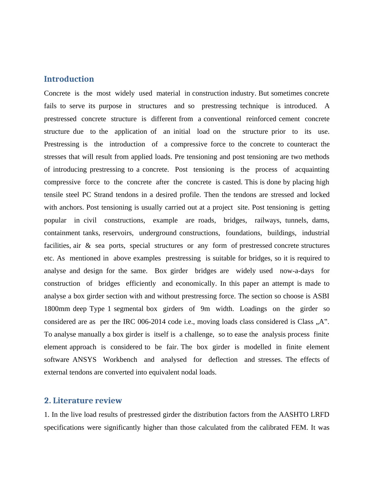
Fig. 1. Cross section of box girder
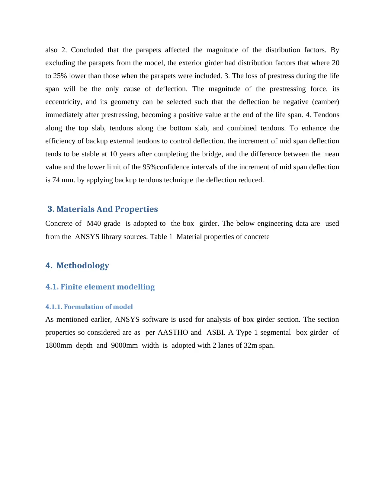
Fig. 2. FEA model in ANSYS
Fig. 2. FEA model in ANSYS
Paraphrase This Document
Need a fresh take? Get an instant paraphrase of this document with our AI Paraphraser
The above FEA model is created using ANSYS considering the section and material properties.
Presentation Concrete is the most generally utilized material in development industry. In any
case, now and then cement neglects to fill its need in structures thus prestressing system is
presented. A prestressed solid structure is not quite the same as an ordinary fortified bond solid
structure because of the utilization of an underlying burden on the structure before its utilization.
Prestressing is the acquaintance of a compressive power with the solid to neutralize the anxieties
that will result from connected burdens. Pre tensioning and post tensioning are two strategies for
acquainting prestressing with a solid. Post tensioning is the way toward familiarizing
compressive power to the solid after the solid is threw. This is finished by putting high pliable
steel PC Strand ligaments in an ideal profile. At that point the ligaments are pushed and bolted
with grapples. Post tensioning is typically done at a task site. Post tensioning is getting famous in
common developments, model are streets, spans, railroads, burrows, dams, regulation tanks,
repositories, underground developments, establishments, structures, mechanical offices, air and
ocean ports, uncommon structures or any type of prestressed solid structures and so on. As
referenced in above precedents prestressing is appropriate for scaffolds, so it is required to
examine and structure for the equivalent. Box brace spans are generally utilized now-a-days for
development of scaffolds productively and monetarily. In this paper an endeavor is made to
investigate a crate support segment with and without prestressing power. The area so pick is
ASBI 1800mm profound Type 1 segmental box braces of 9m width. Loadings on the brace so
considered are according to the IRC 006-2014 code i.e., moving burdens class considered is
Class „A‟. To break down physically a case brace is itself is a test, so to facilitate the
examination procedure limited component approach is viewed as reasonable. The case support is
displayed in limited component programming ANSYS Workbench and broke down for
avoidance and stresses. The impacts of outside ligaments are changed over into equal nodal
loads. 2. Writing audit 1. In the live burden aftereffects of prestressed brace the appropriation
factors from the AASHTO LRFD details were fundamentally higher than those determined from
the adjusted FEM. It was additionally 2. Inferred that the parapets influenced the extent of the
dispersion factors. By barring the parapets from the model, the outside support had appropriation
factors that where 20 to 25% lower than those when the parapets were incorporated. 3. The loss
of prestress amid the life expectancy will be the main source of diversion. The greatness of the
prestressing power, its capriciousness, and its geometry can be chosen to such an extent that the
redirection be negative (camber) following prestressing, turning into a positive incentive toward
the finish of the life expectancy. 4. Ligaments along the top chunk, ligaments along the base
piece, and consolidated ligaments. To improve the proficiency of reinforcement outside
ligaments to control redirection. the augmentation of mid range diversion will in general be
steady at 10 years subsequent to finishing the scaffold, and the contrast between the mean esteem
and the lower furthest reaches of the 95%confidence interims of the addition of mid range
avoidance is 74 mm. by applying reinforcement ligaments method the diversion diminished.
⊘ This is a preview!⊘
Do you want full access?
Subscribe today to unlock all pages.
Trusted by 1+ million students worldwide
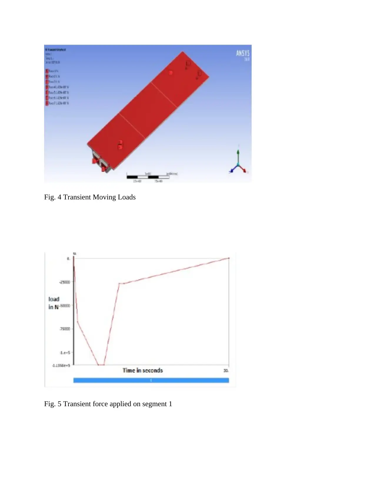
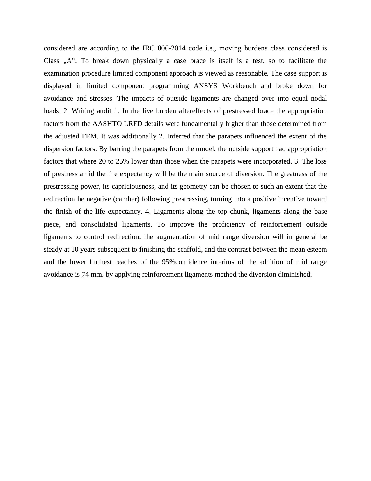
Fig. 4 Transient Moving Loads
Fig. 5 Transient force applied on segment 1
Fig. 5 Transient force applied on segment 1
Paraphrase This Document
Need a fresh take? Get an instant paraphrase of this document with our AI Paraphraser
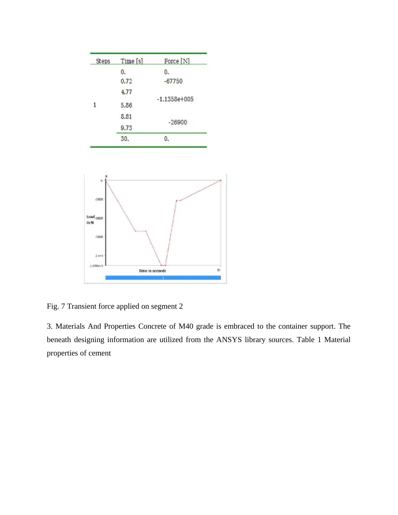
Fig. 7 Transient force applied on segment 2
3. Materials And Properties Concrete of M40 grade is embraced to the container support. The
beneath designing information are utilized from the ANSYS library sources. Table 1 Material
properties of cement
3. Materials And Properties Concrete of M40 grade is embraced to the container support. The
beneath designing information are utilized from the ANSYS library sources. Table 1 Material
properties of cement
4. Technique
4.1. Limited component demonstrating
4.1.1. Definition of model
As referenced before, ANSYS programming is utilized for examination of box brace segment.
The segment properties so considered are according to AASTHO and ASBI. A Type 1 segmental
box support of 1800mm profundity and 9000mm width is embraced with 2 paths of 32m range.
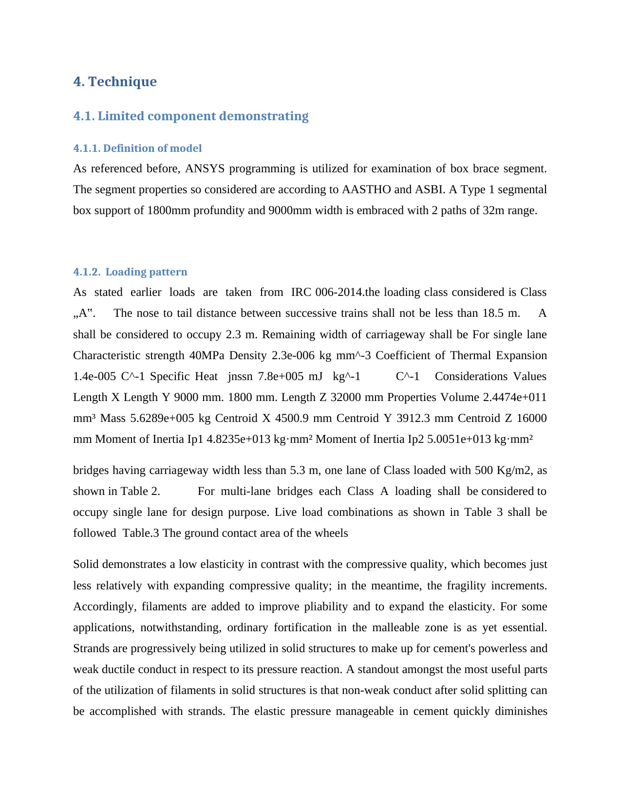
4.1.2. Loading pattern
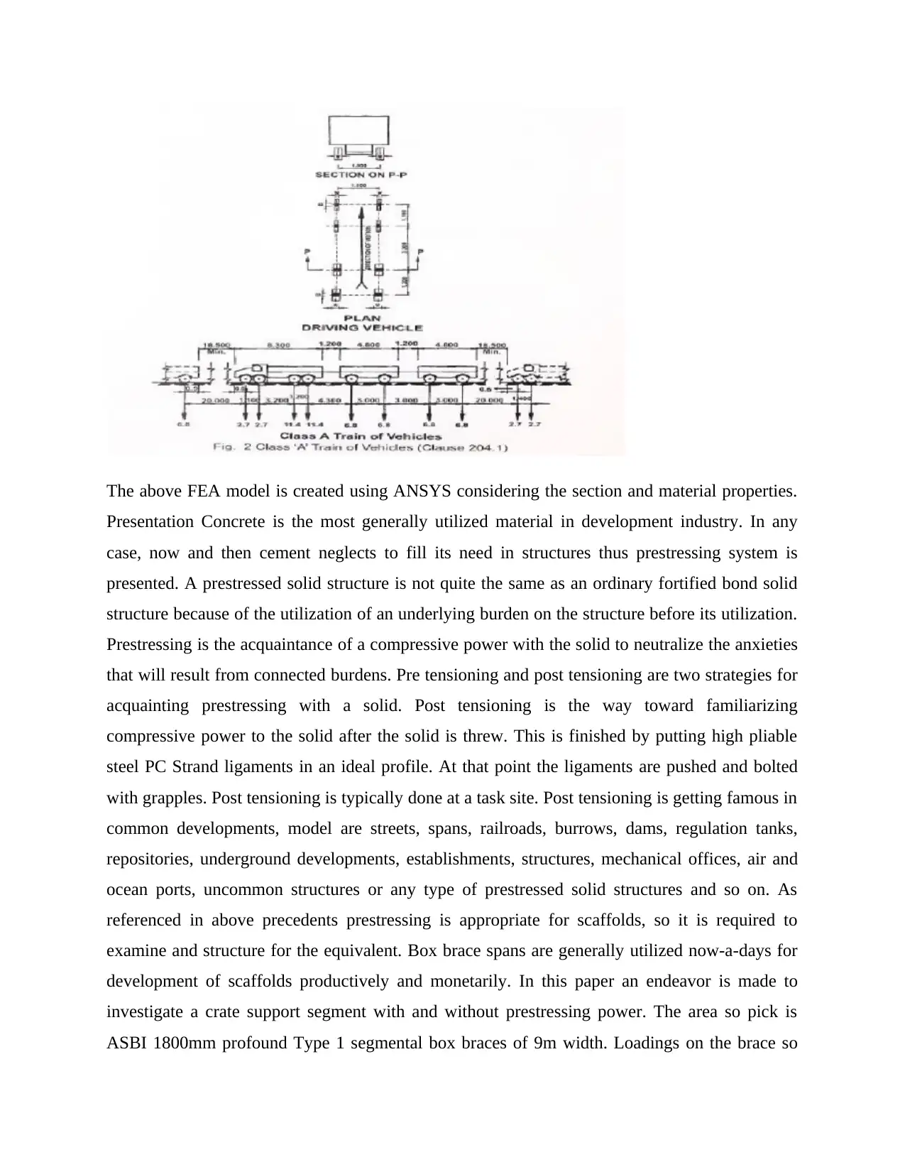
As stated earlier loads are taken from IRC 006-2014.the loading class considered is Class
„A‟. The nose to tail distance between successive trains shall not be less than 18.5 m. A
shall be considered to occupy 2.3 m. Remaining width of carriageway shall be For single lane
Characteristic strength 40MPa Density 2.3e-006 kg mm^-3 Coefficient of Thermal Expansion
1.4e-005 C^-1 Specific Heat jnssn 7.8e+005 mJ kg^-1 C^-1 Considerations Values
Length X Length Y 9000 mm. 1800 mm. Length Z 32000 mm Properties Volume 2.4474e+011
mm³ Mass 5.6289e+005 kg Centroid X 4500.9 mm Centroid Y 3912.3 mm Centroid Z 16000
mm Moment of Inertia Ip1 4.8235e+013 kg·mm² Moment of Inertia Ip2 5.0051e+013 kg·mm²
bridges having carriageway width less than 5.3 m, one lane of Class loaded with 500 Kg/m2, as
shown in Table 2. For multi-lane bridges each Class A loading shall be considered to
occupy single lane for design purpose. Live load combinations as shown in Table 3 shall be
followed Table.3 The ground contact area of the wheels
Solid demonstrates a low elasticity in contrast with the compressive quality, which becomes just
less relatively with expanding compressive quality; in the meantime, the fragility increments.
Accordingly, filaments are added to improve pliability and to expand the elasticity. For some
applications, notwithstanding, ordinary fortification in the malleable zone is as yet essential.
Strands are progressively being utilized in solid structures to make up for cement's powerless and
weak ductile conduct in respect to its pressure reaction. A standout amongst the most useful parts
of the utilization of filaments in solid structures is that non-weak conduct after solid splitting can
be accomplished with strands. The elastic pressure manageable in cement quickly diminishes
4.1. Limited component demonstrating
4.1.1. Definition of model
As referenced before, ANSYS programming is utilized for examination of box brace segment.
The segment properties so considered are according to AASTHO and ASBI. A Type 1 segmental
box support of 1800mm profundity and 9000mm width is embraced with 2 paths of 32m range.
4.1.2. Loading pattern
As stated earlier loads are taken from IRC 006-2014.the loading class considered is Class
„A‟. The nose to tail distance between successive trains shall not be less than 18.5 m. A
shall be considered to occupy 2.3 m. Remaining width of carriageway shall be For single lane
Characteristic strength 40MPa Density 2.3e-006 kg mm^-3 Coefficient of Thermal Expansion
1.4e-005 C^-1 Specific Heat jnssn 7.8e+005 mJ kg^-1 C^-1 Considerations Values
Length X Length Y 9000 mm. 1800 mm. Length Z 32000 mm Properties Volume 2.4474e+011
mm³ Mass 5.6289e+005 kg Centroid X 4500.9 mm Centroid Y 3912.3 mm Centroid Z 16000
mm Moment of Inertia Ip1 4.8235e+013 kg·mm² Moment of Inertia Ip2 5.0051e+013 kg·mm²
bridges having carriageway width less than 5.3 m, one lane of Class loaded with 500 Kg/m2, as
shown in Table 2. For multi-lane bridges each Class A loading shall be considered to
occupy single lane for design purpose. Live load combinations as shown in Table 3 shall be
followed Table.3 The ground contact area of the wheels
Solid demonstrates a low elasticity in contrast with the compressive quality, which becomes just
less relatively with expanding compressive quality; in the meantime, the fragility increments.
Accordingly, filaments are added to improve pliability and to expand the elasticity. For some
applications, notwithstanding, ordinary fortification in the malleable zone is as yet essential.
Strands are progressively being utilized in solid structures to make up for cement's powerless and
weak ductile conduct in respect to its pressure reaction. A standout amongst the most useful parts
of the utilization of filaments in solid structures is that non-weak conduct after solid splitting can
be accomplished with strands. The elastic pressure manageable in cement quickly diminishes
⊘ This is a preview!⊘
Do you want full access?
Subscribe today to unlock all pages.
Trusted by 1+ million students worldwide
following breaking. In fiber-strengthened cement (FRC), then again, strands crossing the split
interfaces altogether add to the heap conveying instrument so significant malleable pressure,
being the Sum of the ductile opposition given by filaments and strain mellowing of the solid
network, individually, can be accomplished even with substantial break widths. Along these
lines, the improved elastic pressure conduct feasible with filaments ought to be reasonably
assessed to precisely anticipate the postcracking reaction of FRC. The bond Resistance of
strengthening bars installed in cement depends essentially on frictional obstruction and
mechanical interlock. The synthetic grip bond, assuming any, comes up short at exceptionally
little slips. Frictional bond gives introductory obstruction against stacking and further stacking
prepares the mechanical interlock between the solid and bar ribs. Mechanical interlock prompts
slanted bearing powers, which thus prompts transverse pliable burdens and interior slanted part
(bond) breaks along strengthening bars. To this end, this examination displayed direct rigidity of
plain concrete and steel fiber fortified cement (SFRC) in Finite Element stage and are assessed
dependent on trial examination. The ANSYS 10.0 Finite Element Analysis (FEA) programming
bundle is utilized to examine the immediate strain examples and presents a decent solid model
for Steel FiberReinforced Concrete (SFRC) just as plain cement made of block and stone total.
Two diverse Poison's proportions for block and stone cement are chosen by contrasting FE yield
and the stress– strain conduct in pressure. A sensible demonstrating of solid utilizing reasonable
component type, satisfactory work measure, suitable limit conditions, practical stacking
condition and legitimate time venturing can assess the overseeing parameters of cement.
Utilizing these overseeing parameters (for example Toxic substance's proportion, rigidity, and
the stress– strain relationship), the dogbane pliable examples are displayed, broke down and
thought about the outcomes accumulated from trial results. After assessment of this parameter by
broad examination, Finite Element (FE) models demonstrated a decent relationship with the test
results and furthermore indicated comparable disappointment designs. This examination is
proposed to approve the FE models with the exploratory outcomes by distinguishing and
utilizing the appropriate parameters of the solid model just as to give an effective FE SFRC show
for breaking down future issues on SFRC and in setting of Bangladesh.
Paraphrase This Document
Need a fresh take? Get an instant paraphrase of this document with our AI Paraphraser
5. Fundamentals
All the Vehicles, airplane and home machines structures are comprised of fixed bar with one end
free or mix of fixed shafts so it winds up important to consider fixed pillar vibration. Coming up
next are fundamental target of burden structure. To Analysis of Bridge with two finishes fixed•
To Analysis of Bridge with two closures fixed utilizing FEA Method.• A definite comprehension
of capacity and setup of Bridge with two ends• fixed.
6. NUMERICAL ANALYSIS BY USING ANSYS
6.1 Basic strides of limited component investigation:
There are three fundamental advances associated with this method, Pre Processor (Building the
model (or) Modeling)• Solution (Applying loads and solving)• Post Processor (Reviewing the
results)•
6.2 Numerical Approach for Transverse Vibration of Fixed Free Beam:
We will currently research the free vibration of fixed free bar utilizing the ANSYS program, a
thorough limited component bundle. We utilize the ANSYS auxiliary bundle to dissect the
vibration of fixed free shaft. Limited component strategies at present in all respects broadly
utilized in designing examination. The strategies are utilized widely in the investigation of strong
and structures and of warmth exchange and liquids and for sure, limited component techniques
are valuable in for all intents and purposes each field of designing examination.
6.3 Portrayal of the limited component technique:
The physical issue normally includes a real structure or auxiliary segment subject to specific
burdens. The glorification of the physical issue to a scientific model requires certain suspicions
that together lead to differential conditions administering the numerical model. Since the limited
component arrangement system is a numerical method, it is important to get to the arrangement
exactness. In the event that the precision criteria are not met, the numerical arrangement must be
rehashed with refined arrangement parameters until an adequate exactness is come to.
6.3 Imperative highlights of limited component strategy coming up next are
the fundamental highlights of the limited component technique:
Division of entire in to parts, which permits portrayal of geometrically complex spaces as
accumulation of straightforward areas that, empowers an efficient induction of the estimation
capacities. Induction of guess works over every component the estimation capacities are
arithmetical polynomials that are determined utilizing interjection hypothesis. 3.5. Limit
Conditions: The coincided model is then broke down (static) and the limit conditions are: One
end is fixed (All DOF
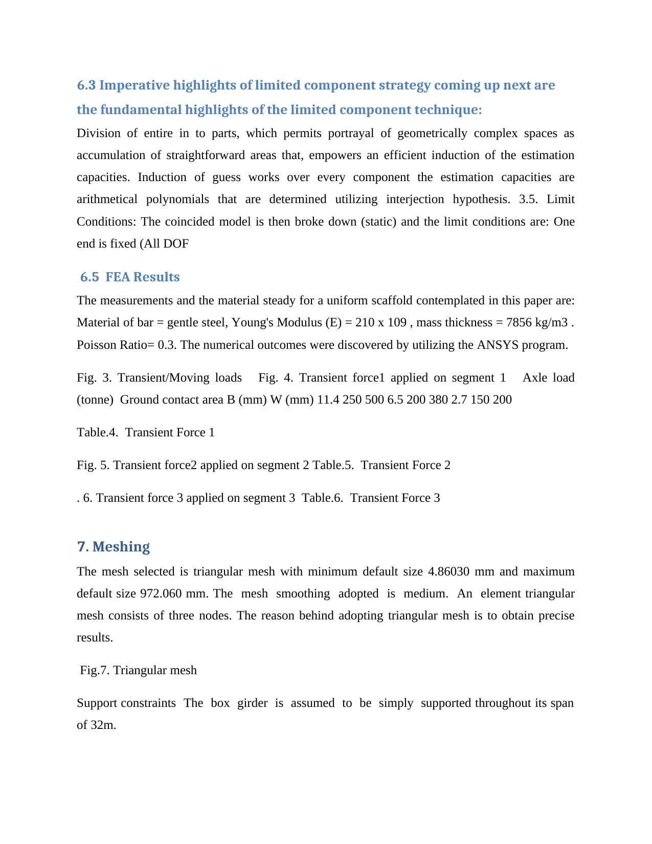
6.5 FEA Results
The measurements and the material steady for a uniform scaffold contemplated in this paper are:
Material of bar = gentle steel, Young's Modulus (E) = 210 x 109 , mass thickness = 7856 kg/m3 .
Poisson Ratio= 0.3. The numerical outcomes were discovered by utilizing the ANSYS program.
Fig. 3. Transient/Moving loads Fig. 4. Transient force1 applied on segment 1 Axle load
(tonne) Ground contact area B (mm) W (mm) 11.4 250 500 6.5 200 380 2.7 150 200
Table.4. Transient Force 1
Fig. 5. Transient force2 applied on segment 2 Table.5. Transient Force 2
. 6. Transient force 3 applied on segment 3 Table.6. Transient Force 3
7. Meshing
The mesh selected is triangular mesh with minimum default size 4.86030 mm and maximum
default size 972.060 mm. The mesh smoothing adopted is medium. An element triangular
mesh consists of three nodes. The reason behind adopting triangular mesh is to obtain precise
results.
Fig.7. Triangular mesh
Support constraints The box girder is assumed to be simply supported throughout its span
of 32m.
the fundamental highlights of the limited component technique:
Division of entire in to parts, which permits portrayal of geometrically complex spaces as
accumulation of straightforward areas that, empowers an efficient induction of the estimation
capacities. Induction of guess works over every component the estimation capacities are
arithmetical polynomials that are determined utilizing interjection hypothesis. 3.5. Limit
Conditions: The coincided model is then broke down (static) and the limit conditions are: One
end is fixed (All DOF
6.5 FEA Results
The measurements and the material steady for a uniform scaffold contemplated in this paper are:
Material of bar = gentle steel, Young's Modulus (E) = 210 x 109 , mass thickness = 7856 kg/m3 .
Poisson Ratio= 0.3. The numerical outcomes were discovered by utilizing the ANSYS program.
Fig. 3. Transient/Moving loads Fig. 4. Transient force1 applied on segment 1 Axle load
(tonne) Ground contact area B (mm) W (mm) 11.4 250 500 6.5 200 380 2.7 150 200
Table.4. Transient Force 1
Fig. 5. Transient force2 applied on segment 2 Table.5. Transient Force 2
. 6. Transient force 3 applied on segment 3 Table.6. Transient Force 3
7. Meshing
The mesh selected is triangular mesh with minimum default size 4.86030 mm and maximum
default size 972.060 mm. The mesh smoothing adopted is medium. An element triangular
mesh consists of three nodes. The reason behind adopting triangular mesh is to obtain precise
results.
Fig.7. Triangular mesh
Support constraints The box girder is assumed to be simply supported throughout its span
of 32m.
⊘ This is a preview!⊘
Do you want full access?
Subscribe today to unlock all pages.
Trusted by 1+ million students worldwide
1 out of 21
Your All-in-One AI-Powered Toolkit for Academic Success.
+13062052269
info@desklib.com
Available 24*7 on WhatsApp / Email
![[object Object]](/_next/static/media/star-bottom.7253800d.svg)
Unlock your academic potential
Copyright © 2020–2026 A2Z Services. All Rights Reserved. Developed and managed by ZUCOL.