Antennas and Connectivity: Wire, Traveling Wave, and Antenna Types
VerifiedAdded on 2020/03/23
|14
|2486
|236
Report
AI Summary
This report delves into the specifications of antennas, exploring wire and traveling wave antenna types, including dipole, Yagi-Uda, and parabolic reflector antennas. It examines antenna characteristics like gain, aperture, bandwidth, directivity, and polarization. The report also covers antenna modeling using CST Studio Suite, discussing beamforming techniques and the IEEE Standard 1597.1 for electromagnetic simulations. The analysis includes a comparison of antenna types, their applications, and the importance of these technologies in modern communication systems, such as intelligent transport systems, and wireless communications.
Running head: ANTENNAS AND CONNECTIVITY
Antennas and connectivity
Name of the student
Name of the University
Author Note
Antennas and connectivity
Name of the student
Name of the University
Author Note
Paraphrase This Document
Need a fresh take? Get an instant paraphrase of this document with our AI Paraphraser
1ANTENNAS AND CONNECTIVITY
Executive summary
The following report discusses about the specifications of antennas. The two chosen types of
antennas are the wire antennas and travelling wave antennas. In addition, the report also
discusses about three different antenna types known as the dipole, Yagi-Uda and the parabolic
reflector antennas. Furthermore, the definition of modeling of antennas by using the CST Studio
Suite along with the IEEE Standard 1597.1 is also discussed in the report.
2ANTENNAS AND CONNECTIVITY
Table of Contents
Introduction:....................................................................................................................................3
Discussion:.......................................................................................................................................3
1. Wire and travelling wave antennas:.........................................................................................3
2. Antenna characteristics:...........................................................................................................3
3. Types of antenna:.....................................................................................................................5
4. Differentiation among the antennas:........................................................................................8
5. CST studio suite:......................................................................................................................8
6. Beamforming:..........................................................................................................................9
7. IEEE Standard 1597.1:............................................................................................................9
Conclusion:....................................................................................................................................10
References:....................................................................................................................................11
⊘ This is a preview!⊘
Do you want full access?
Subscribe today to unlock all pages.
Trusted by 1+ million students worldwide
3ANTENNAS AND CONNECTIVITY
Introduction:
Antennas are devices which are used to convert the electronic signals coming from a
source into electronic waves to be sent to the destination. The most basic components of a circuit
are the presence of antennas in the system as they are responsible for the interconnection among
the sender and the receiver. In addition, the sender and the receiver have the free space to serve
as the guided media for the communication.
Discussion:
The antennas have major characteristics that define the properties of working of them.
These are the antenna gain, aperture, bandwidth, directivity and polarization, and effective
length.
1. Wire and travelling wave antennas:
The linear or curved antennas are termed as the wire antennas. The main use of these
antennas is due to the fact of low cost and simple designs [1]. They are mainly divided in to the
dipole antennas, short dipole antennas, monopole antennas and the loop antennas.
The travelling wave antennas are those types which uses the travelling wave on a guided
media for radiating mechanisms. Their main operations include the travelling of the radio waves
in a single direction. They are mainly divided into the helical antennas and the Yagi-Uda
antennas.
Paraphrase This Document
Need a fresh take? Get an instant paraphrase of this document with our AI Paraphraser
4ANTENNAS AND CONNECTIVITY
2. Antenna characteristics:
The major antenna characteristics are used to define the operations of the antenna. These
include the antenna gain, aperture, bandwidth and directivity, polarization, and effective length
[1].
Antenna gain:
The gain of the antenna is used to define the degree of radial pattern of the antenna. An
antenna with a much high gain has a more effective radiation pattern than an antenna with a low
gain [2]. The manufacturing of the antennas are done to facilitate the increase of directed power
in the wanted directions and vice-versa.
Aperture:
The aperture, also termed as the effective aperture is used to associate with the
transmission and the reception of electromagnetic signals. The collective area of the antenna is
associated with the main power received [1]. This area is termed as the effective aperture.
A=pr/pd (m^2),
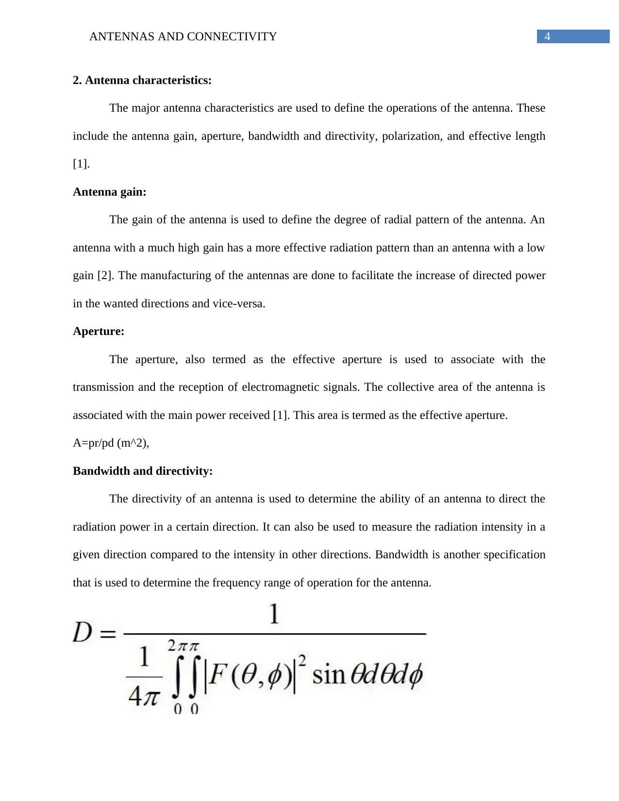
Bandwidth and directivity:
The directivity of an antenna is used to determine the ability of an antenna to direct the
radiation power in a certain direction. It can also be used to measure the radiation intensity in a
given direction compared to the intensity in other directions. Bandwidth is another specification
that is used to determine the frequency range of operation for the antenna.
2. Antenna characteristics:
The major antenna characteristics are used to define the operations of the antenna. These
include the antenna gain, aperture, bandwidth and directivity, polarization, and effective length
[1].
Antenna gain:
The gain of the antenna is used to define the degree of radial pattern of the antenna. An
antenna with a much high gain has a more effective radiation pattern than an antenna with a low
gain [2]. The manufacturing of the antennas are done to facilitate the increase of directed power
in the wanted directions and vice-versa.
Aperture:
The aperture, also termed as the effective aperture is used to associate with the
transmission and the reception of electromagnetic signals. The collective area of the antenna is
associated with the main power received [1]. This area is termed as the effective aperture.
A=pr/pd (m^2),
Bandwidth and directivity:
The directivity of an antenna is used to determine the ability of an antenna to direct the
radiation power in a certain direction. It can also be used to measure the radiation intensity in a
given direction compared to the intensity in other directions. Bandwidth is another specification
that is used to determine the frequency range of operation for the antenna.
5ANTENNAS AND CONNECTIVITY
Fig: 1
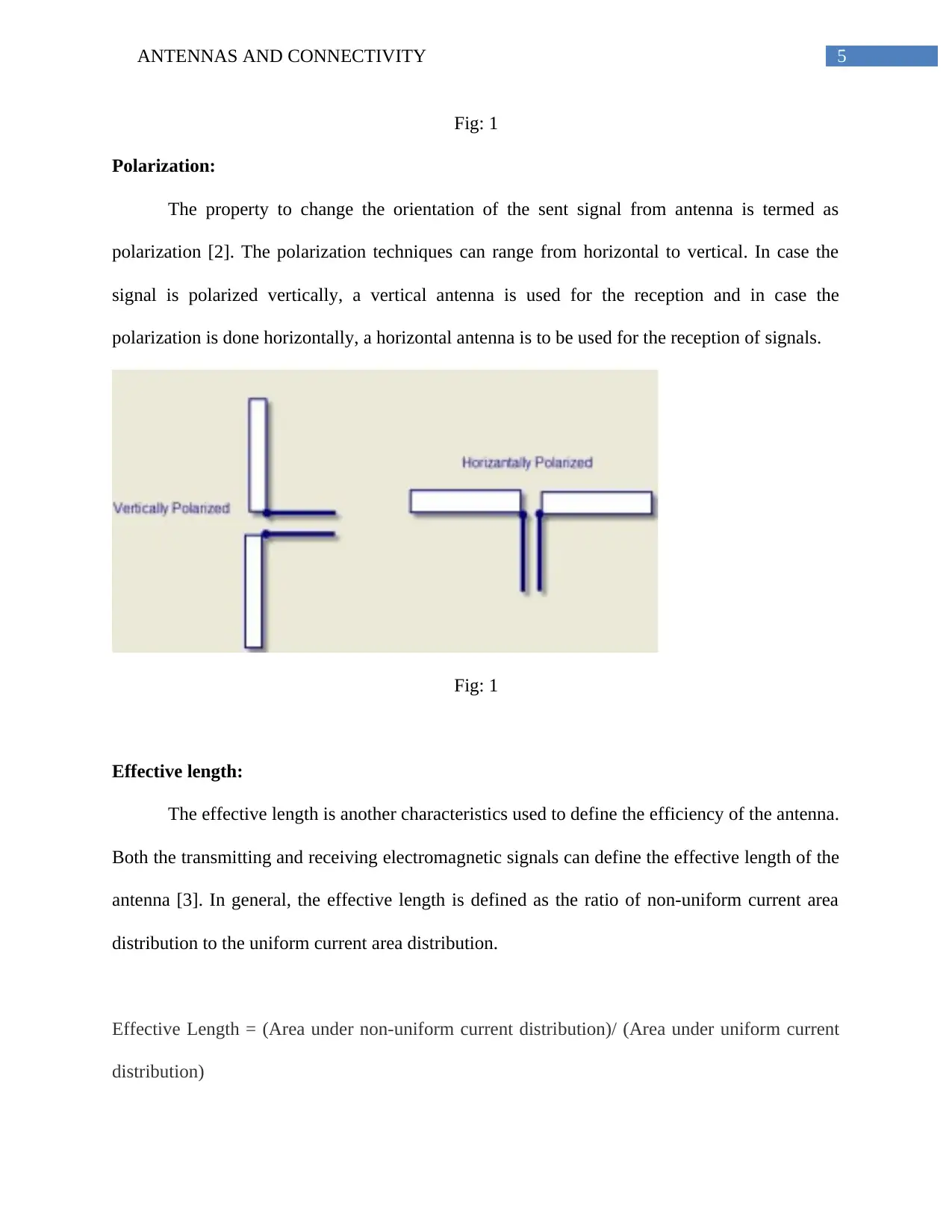
Polarization:
The property to change the orientation of the sent signal from antenna is termed as
polarization [2]. The polarization techniques can range from horizontal to vertical. In case the
signal is polarized vertically, a vertical antenna is used for the reception and in case the
polarization is done horizontally, a horizontal antenna is to be used for the reception of signals.
Fig: 1
Effective length:
The effective length is another characteristics used to define the efficiency of the antenna.
Both the transmitting and receiving electromagnetic signals can define the effective length of the
antenna [3]. In general, the effective length is defined as the ratio of non-uniform current area
distribution to the uniform current area distribution.
Effective Length = (Area under non-uniform current distribution)/ (Area under uniform current
distribution)
Fig: 1
Polarization:
The property to change the orientation of the sent signal from antenna is termed as
polarization [2]. The polarization techniques can range from horizontal to vertical. In case the
signal is polarized vertically, a vertical antenna is used for the reception and in case the
polarization is done horizontally, a horizontal antenna is to be used for the reception of signals.
Fig: 1
Effective length:
The effective length is another characteristics used to define the efficiency of the antenna.
Both the transmitting and receiving electromagnetic signals can define the effective length of the
antenna [3]. In general, the effective length is defined as the ratio of non-uniform current area
distribution to the uniform current area distribution.
Effective Length = (Area under non-uniform current distribution)/ (Area under uniform current
distribution)
⊘ This is a preview!⊘
Do you want full access?
Subscribe today to unlock all pages.
Trusted by 1+ million students worldwide
6ANTENNAS AND CONNECTIVITY
3. Types of antenna:
This section of the report is used to reference the operations of three different antennas.
These are the dipole antennas, Yagi-Uda antennas and the parabolic reflector antenna.
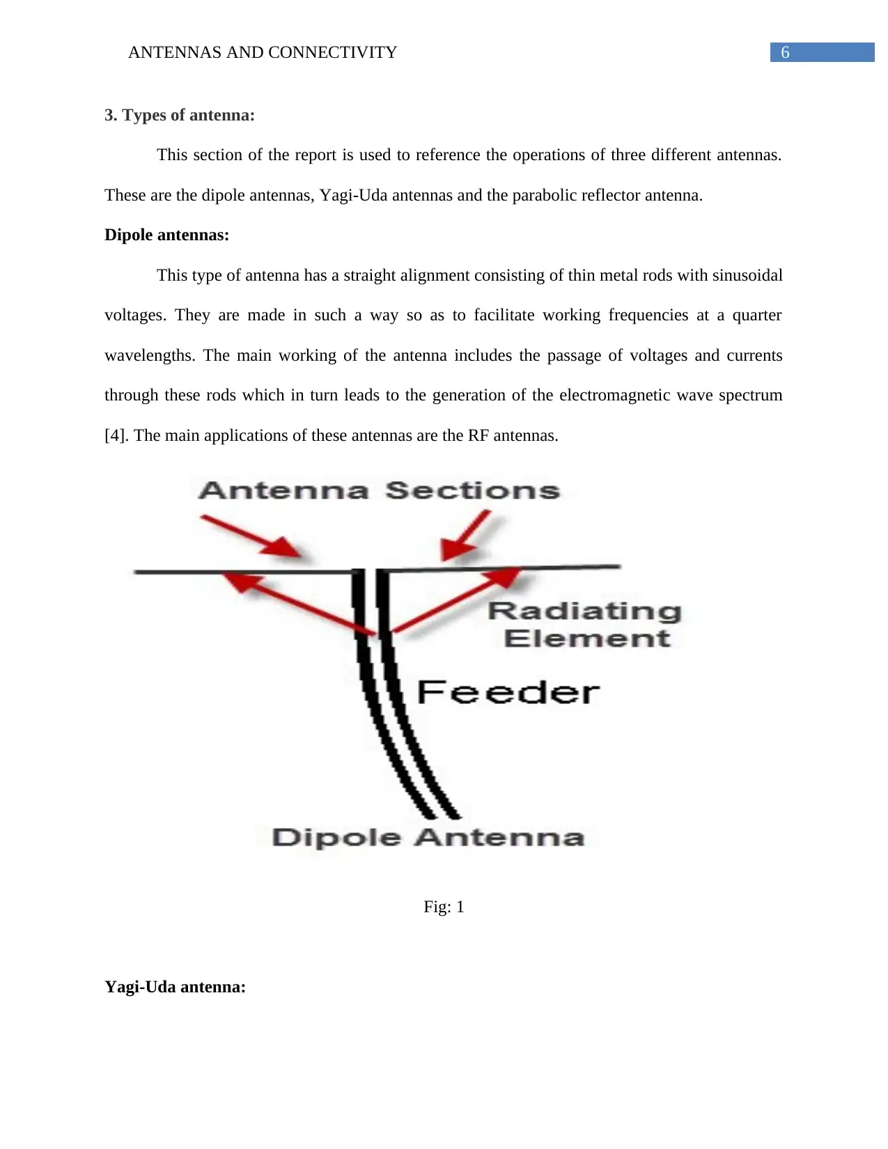
Dipole antennas:
This type of antenna has a straight alignment consisting of thin metal rods with sinusoidal
voltages. They are made in such a way so as to facilitate working frequencies at a quarter
wavelengths. The main working of the antenna includes the passage of voltages and currents
through these rods which in turn leads to the generation of the electromagnetic wave spectrum
[4]. The main applications of these antennas are the RF antennas.
Fig: 1
Yagi-Uda antenna:
3. Types of antenna:
This section of the report is used to reference the operations of three different antennas.
These are the dipole antennas, Yagi-Uda antennas and the parabolic reflector antenna.
Dipole antennas:
This type of antenna has a straight alignment consisting of thin metal rods with sinusoidal
voltages. They are made in such a way so as to facilitate working frequencies at a quarter
wavelengths. The main working of the antenna includes the passage of voltages and currents
through these rods which in turn leads to the generation of the electromagnetic wave spectrum
[4]. The main applications of these antennas are the RF antennas.
Fig: 1
Yagi-Uda antenna:
Paraphrase This Document
Need a fresh take? Get an instant paraphrase of this document with our AI Paraphraser
7ANTENNAS AND CONNECTIVITY
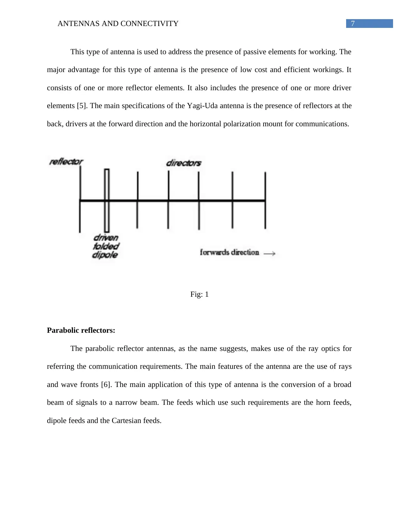
This type of antenna is used to address the presence of passive elements for working. The
major advantage for this type of antenna is the presence of low cost and efficient workings. It
consists of one or more reflector elements. It also includes the presence of one or more driver
elements [5]. The main specifications of the Yagi-Uda antenna is the presence of reflectors at the
back, drivers at the forward direction and the horizontal polarization mount for communications.
Fig: 1
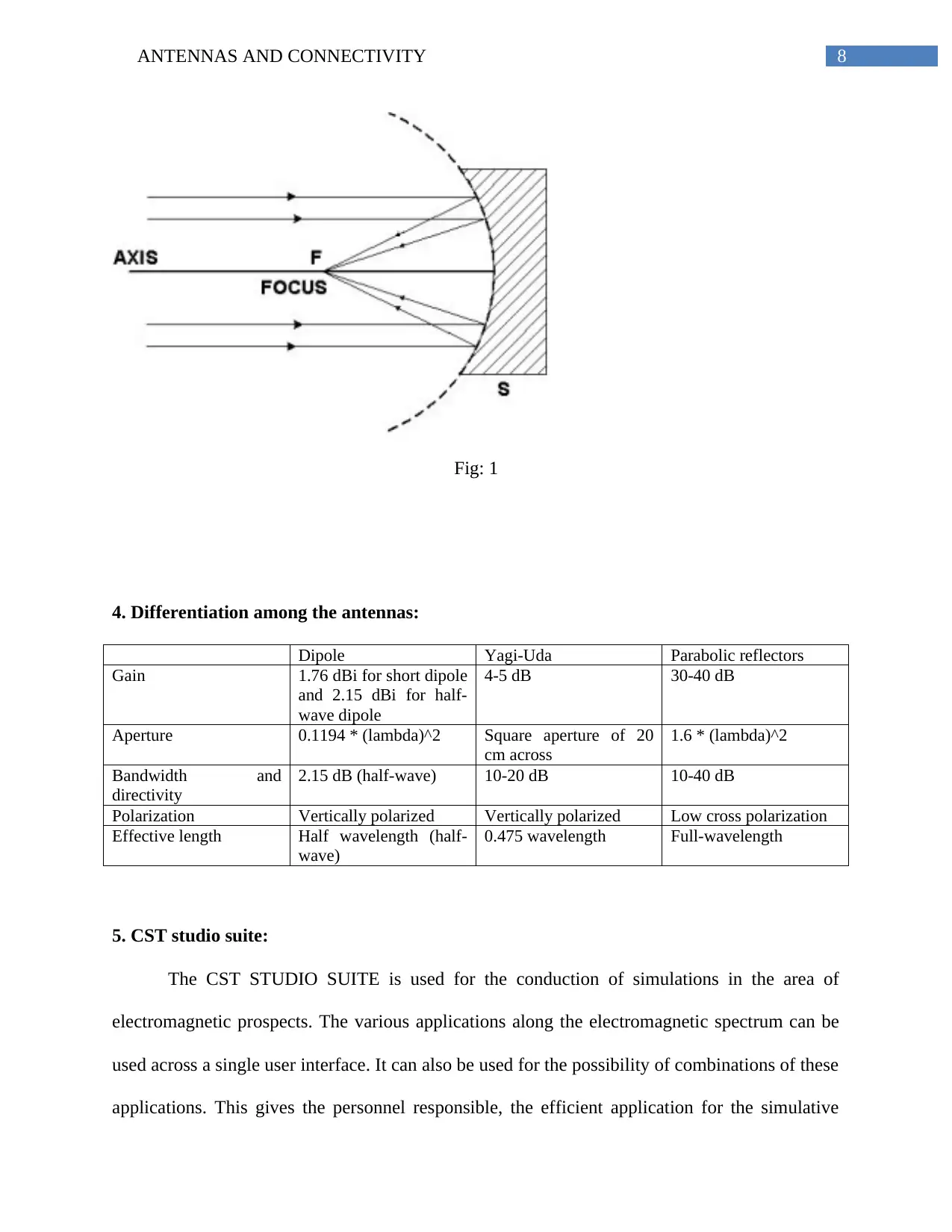
Parabolic reflectors:
The parabolic reflector antennas, as the name suggests, makes use of the ray optics for
referring the communication requirements. The main features of the antenna are the use of rays
and wave fronts [6]. The main application of this type of antenna is the conversion of a broad
beam of signals to a narrow beam. The feeds which use such requirements are the horn feeds,
dipole feeds and the Cartesian feeds.
This type of antenna is used to address the presence of passive elements for working. The
major advantage for this type of antenna is the presence of low cost and efficient workings. It
consists of one or more reflector elements. It also includes the presence of one or more driver
elements [5]. The main specifications of the Yagi-Uda antenna is the presence of reflectors at the
back, drivers at the forward direction and the horizontal polarization mount for communications.
Fig: 1
Parabolic reflectors:
The parabolic reflector antennas, as the name suggests, makes use of the ray optics for
referring the communication requirements. The main features of the antenna are the use of rays
and wave fronts [6]. The main application of this type of antenna is the conversion of a broad
beam of signals to a narrow beam. The feeds which use such requirements are the horn feeds,
dipole feeds and the Cartesian feeds.
8ANTENNAS AND CONNECTIVITY
Fig: 1
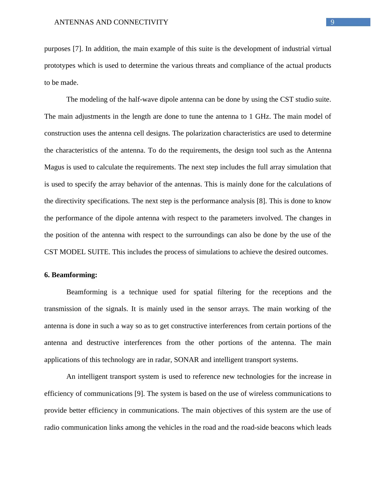
4. Differentiation among the antennas:
Dipole Yagi-Uda Parabolic reflectors
Gain 1.76 dBi for short dipole
and 2.15 dBi for half-
wave dipole
4-5 dB 30-40 dB
Aperture 0.1194 * (lambda)^2 Square aperture of 20
cm across
1.6 * (lambda)^2
Bandwidth and
directivity
2.15 dB (half-wave) 10-20 dB 10-40 dB
Polarization Vertically polarized Vertically polarized Low cross polarization
Effective length Half wavelength (half-
wave)
0.475 wavelength Full-wavelength
5. CST studio suite:
The CST STUDIO SUITE is used for the conduction of simulations in the area of
electromagnetic prospects. The various applications along the electromagnetic spectrum can be
used across a single user interface. It can also be used for the possibility of combinations of these
applications. This gives the personnel responsible, the efficient application for the simulative
Fig: 1
4. Differentiation among the antennas:
Dipole Yagi-Uda Parabolic reflectors
Gain 1.76 dBi for short dipole
and 2.15 dBi for half-
wave dipole
4-5 dB 30-40 dB
Aperture 0.1194 * (lambda)^2 Square aperture of 20
cm across
1.6 * (lambda)^2
Bandwidth and
directivity
2.15 dB (half-wave) 10-20 dB 10-40 dB
Polarization Vertically polarized Vertically polarized Low cross polarization
Effective length Half wavelength (half-
wave)
0.475 wavelength Full-wavelength
5. CST studio suite:
The CST STUDIO SUITE is used for the conduction of simulations in the area of
electromagnetic prospects. The various applications along the electromagnetic spectrum can be
used across a single user interface. It can also be used for the possibility of combinations of these
applications. This gives the personnel responsible, the efficient application for the simulative
⊘ This is a preview!⊘
Do you want full access?
Subscribe today to unlock all pages.
Trusted by 1+ million students worldwide
9ANTENNAS AND CONNECTIVITY
purposes [7]. In addition, the main example of this suite is the development of industrial virtual
prototypes which is used to determine the various threats and compliance of the actual products
to be made.
The modeling of the half-wave dipole antenna can be done by using the CST studio suite.
The main adjustments in the length are done to tune the antenna to 1 GHz. The main model of
construction uses the antenna cell designs. The polarization characteristics are used to determine
the characteristics of the antenna. To do the requirements, the design tool such as the Antenna
Magus is used to calculate the requirements. The next step includes the full array simulation that
is used to specify the array behavior of the antennas. This is mainly done for the calculations of
the directivity specifications. The next step is the performance analysis [8]. This is done to know
the performance of the dipole antenna with respect to the parameters involved. The changes in
the position of the antenna with respect to the surroundings can also be done by the use of the
CST MODEL SUITE. This includes the process of simulations to achieve the desired outcomes.
6. Beamforming:
Beamforming is a technique used for spatial filtering for the receptions and the
transmission of the signals. It is mainly used in the sensor arrays. The main working of the
antenna is done in such a way so as to get constructive interferences from certain portions of the
antenna and destructive interferences from the other portions of the antenna. The main
applications of this technology are in radar, SONAR and intelligent transport systems.
An intelligent transport system is used to reference new technologies for the increase in
efficiency of communications [9]. The system is based on the use of wireless communications to
provide better efficiency in communications. The main objectives of this system are the use of
radio communication links among the vehicles in the road and the road-side beacons which leads
Paraphrase This Document
Need a fresh take? Get an instant paraphrase of this document with our AI Paraphraser
10ANTENNAS AND CONNECTIVITY
to the formation of ad-hoc network. The directional antennas can be used to increase the
efficiency of the transportation features. In addition, the use of array with wide bandwidth and
beam steering capabilities are required for the increasing efficiency in transportation services.
This can also be done by the use of beamforming networks (BFN) to facilitate control over the
phase and the amplitude of the elements of the array in the antenna [10]. The main examples of
the network are Butler Matrix and Rotman lens.
7. IEEE Standard 1597.1:
The IEEE Standard 1597.1 is a technique to simulate and model the various
electromagnetic codes. It can be applied to an extensive list of electromagnetic applications. The
major use of this standard is the digital mapping and simulation of the models and codes present
of the electromagnetic spectrums. The IEEE Standard 1597.1 can also be used for the
electromagnetic compatibility addressing. It can also be used for the detection of the radar cross-
sectional areas. Furthermore, the integrity of the signals along with the antenna integrity can also
be referenced by the IEEE Standard 1597.1 [11]. The main aim for the use of the IEEE Standard
1597.1 is the comparison and validation of the data sets. These can be obtained by measurements
of values, alternative methods of code retrieval, analytical methods of information gathering and
canonical methods.
The main use of the IEEE Standard 1597.1 is the comparison of the analytical data and
measurements. This can be done by the use of value measurements, reception of the codes for
analysis from alternate sources, analytical methods for code referencing and he canonical ways
of information gathering.

11ANTENNAS AND CONNECTIVITY
Conclusion:
Thus, it can be concluded from the report that the use of various antennas can be used for
use in intelligent transport systems. In addition, the IEEE Standard 1597.1 is also used for the
application of the analysis of the gathered data. Wireless communications helps various aspects
to modernize their services and increase their operational efficiencies.
⊘ This is a preview!⊘
Do you want full access?
Subscribe today to unlock all pages.
Trusted by 1+ million students worldwide
1 out of 14
Related Documents


Your All-in-One AI-Powered Toolkit for Academic Success.
+13062052269
info@desklib.com
Available 24*7 on WhatsApp / Email
![[object Object]](/_next/static/media/star-bottom.7253800d.svg)
Unlock your academic potential
Copyright © 2020–2026 A2Z Services. All Rights Reserved. Developed and managed by ZUCOL.