Autonomous Shield-Bot Drive: A Robotics Project with Arduino
VerifiedAdded on 2022/08/16
|7
|6412
|214
Project
AI Summary
This project report details the creation of an autonomous Shield-Bot robot using an Arduino board. The project involves programming the robot to move independently, integrating proximity and distance sensors, and implementing actuators for control. The Shield-Bot is a stackable Arduino shield designed for beginners, featuring line-following sensors and expansion ports. The challenge is to make the robot move autonomously in a straight line, pause, and turn 180 degrees. The design includes assembling the robot, wiring motors to motor controllers, and programming the Arduino. The programming section covers controlling motor speeds, sensor integration for obstacle detection, and implementing an autonomous mode where the robot navigates using sensor input. The solution includes detailed instructions, code snippets, and explanations to guide the construction and programming of the autonomous robot.
Arduino Shied-Bot Autonomous Drive
1st Author
1st author's affiliation
1st line of address
2nd line of address
Telephone number, incl. country code
1st author's E-mail address
2nd Author
2nd author's affiliation
1st line of address
2nd line of address
Telephone number, incl. country code
2nd E-mail
3rd Author
3rd author's affiliation
1st line of address
2nd line of address
Telephone number, incl. country code
3rd E-mail
ABSTRACT
This project entails making the shield robot move about
autonomously. This will involve using Arduino software to create
a code for the robot to work without being controlled. It will
include insertion of proximity and distance sensors and actuators.
This article discusses the whole process.
Keywords
Arduino software, Shield-Bot, autonomous drive, robotics,
coding.
1. INTRODUCTION
The Shield Bot is a programmable mobile robot that uses an
Arduino board. The robot is programmable using the Arduino
programming environment and provides a breadboard to easily
add your electronic components, sensors or your own electronic
circuits [1].
The Shield Bot is a stackable Arduino Shield that transforms your
Arduino into a fully featured beginner robot. The Shield Bot has
been designed and specially equipped with on board line
following sensors and expansion ports to be the robotic buddy that
will teach you about robotics, electronics, and programming. It is
also packed full of expansion ports so it can also be the perfect
base for any desktop robotics project!
2. PROJECT
2.1. The Approach
The challenge is to make the Shield Bot move autonomously in a
straight line for exactly 2 metres on a track of unknown terrain,
which may also contain inclines or declines, pausing for 5 seconds
and then turning 180o to return to its starting position.
The aim of this project is to create a rover that is able to
independently follow a certain line path traced on the floor. The
identification of the path is done by the five sensors integrated on
the Shield Bot 1.2 rover. Also, a manual mode has been
implemented, to drive through user's command, received via
Serial line.
3. DESIGN
This project is based on the Arduino rover, so you can review
the Assemble the Rover and Electrical Assembly Steps. I have
added detailed directions, as I have changed the orientation of the
Arduino101 mount point and use a second motor controller to
reduce likely hood of loose wires after collisions [2].
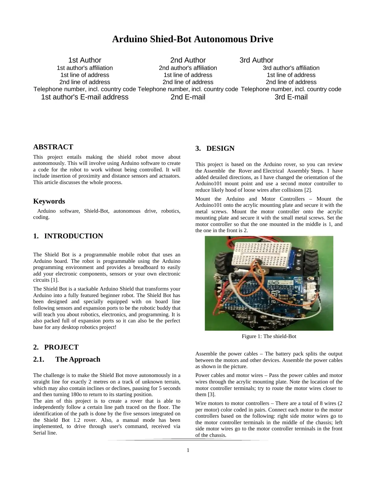
Mount the Arduino and Motor Controllers – Mount the
Arduino101 onto the acrylic mounting plate and secure it with the
metal screws. Mount the motor controller onto the acrylic
mounting plate and secure it with the small metal screws. Set the
motor controller so that the one mounted in the middle is 1, and
the one in the front is 2.
Figure 1: The shield-Bot
Assemble the power cables – The battery pack splits the output
between the motors and other devices. Assemble the power cables
as shown in the picture.
Power cables and motor wires – Pass the power cables and motor
wires through the acrylic mounting plate. Note the location of the
motor controller terminals; try to route the motor wires closer to
them [3].
Wire motors to motor controllers – There are a total of 8 wires (2
per motor) color coded in pairs. Connect each motor to the motor
controllers based on the following: right side motor wires go to
the motor controller terminals in the middle of the chassis; left
side motor wires go to the motor controller terminals in the front
of the chassis.
1
1st Author
1st author's affiliation
1st line of address
2nd line of address
Telephone number, incl. country code
1st author's E-mail address
2nd Author
2nd author's affiliation
1st line of address
2nd line of address
Telephone number, incl. country code
2nd E-mail
3rd Author
3rd author's affiliation
1st line of address
2nd line of address
Telephone number, incl. country code
3rd E-mail
ABSTRACT
This project entails making the shield robot move about
autonomously. This will involve using Arduino software to create
a code for the robot to work without being controlled. It will
include insertion of proximity and distance sensors and actuators.
This article discusses the whole process.
Keywords
Arduino software, Shield-Bot, autonomous drive, robotics,
coding.
1. INTRODUCTION
The Shield Bot is a programmable mobile robot that uses an
Arduino board. The robot is programmable using the Arduino
programming environment and provides a breadboard to easily
add your electronic components, sensors or your own electronic
circuits [1].
The Shield Bot is a stackable Arduino Shield that transforms your
Arduino into a fully featured beginner robot. The Shield Bot has
been designed and specially equipped with on board line
following sensors and expansion ports to be the robotic buddy that
will teach you about robotics, electronics, and programming. It is
also packed full of expansion ports so it can also be the perfect
base for any desktop robotics project!
2. PROJECT
2.1. The Approach
The challenge is to make the Shield Bot move autonomously in a
straight line for exactly 2 metres on a track of unknown terrain,
which may also contain inclines or declines, pausing for 5 seconds
and then turning 180o to return to its starting position.
The aim of this project is to create a rover that is able to
independently follow a certain line path traced on the floor. The
identification of the path is done by the five sensors integrated on
the Shield Bot 1.2 rover. Also, a manual mode has been
implemented, to drive through user's command, received via
Serial line.
3. DESIGN
This project is based on the Arduino rover, so you can review
the Assemble the Rover and Electrical Assembly Steps. I have
added detailed directions, as I have changed the orientation of the
Arduino101 mount point and use a second motor controller to
reduce likely hood of loose wires after collisions [2].
Mount the Arduino and Motor Controllers – Mount the
Arduino101 onto the acrylic mounting plate and secure it with the
metal screws. Mount the motor controller onto the acrylic
mounting plate and secure it with the small metal screws. Set the
motor controller so that the one mounted in the middle is 1, and
the one in the front is 2.
Figure 1: The shield-Bot
Assemble the power cables – The battery pack splits the output
between the motors and other devices. Assemble the power cables
as shown in the picture.
Power cables and motor wires – Pass the power cables and motor
wires through the acrylic mounting plate. Note the location of the
motor controller terminals; try to route the motor wires closer to
them [3].
Wire motors to motor controllers – There are a total of 8 wires (2
per motor) color coded in pairs. Connect each motor to the motor
controllers based on the following: right side motor wires go to
the motor controller terminals in the middle of the chassis; left
side motor wires go to the motor controller terminals in the front
of the chassis.
1
Paraphrase This Document
Need a fresh take? Get an instant paraphrase of this document with our AI Paraphraser
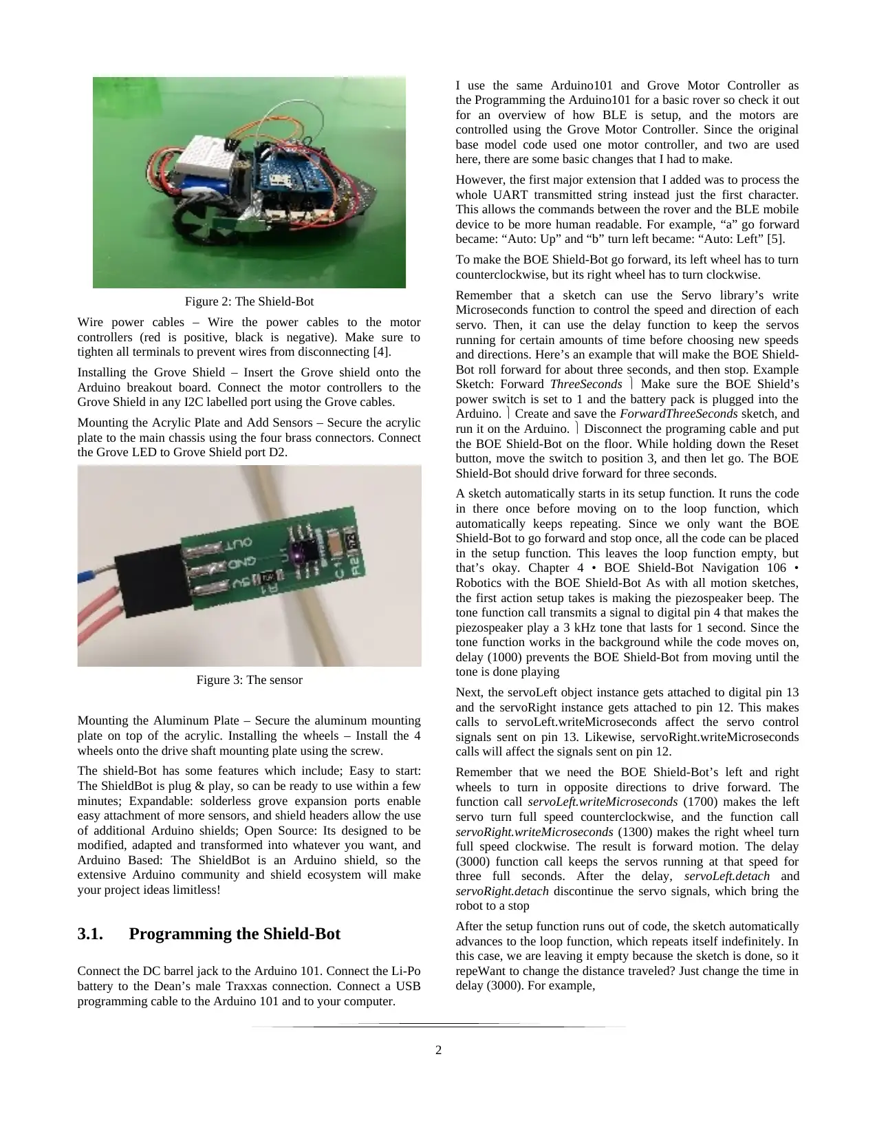
Figure 2: The Shield-Bot
Wire power cables – Wire the power cables to the motor
controllers (red is positive, black is negative). Make sure to
tighten all terminals to prevent wires from disconnecting [4].
Installing the Grove Shield – Insert the Grove shield onto the
Arduino breakout board. Connect the motor controllers to the
Grove Shield in any I2C labelled port using the Grove cables.
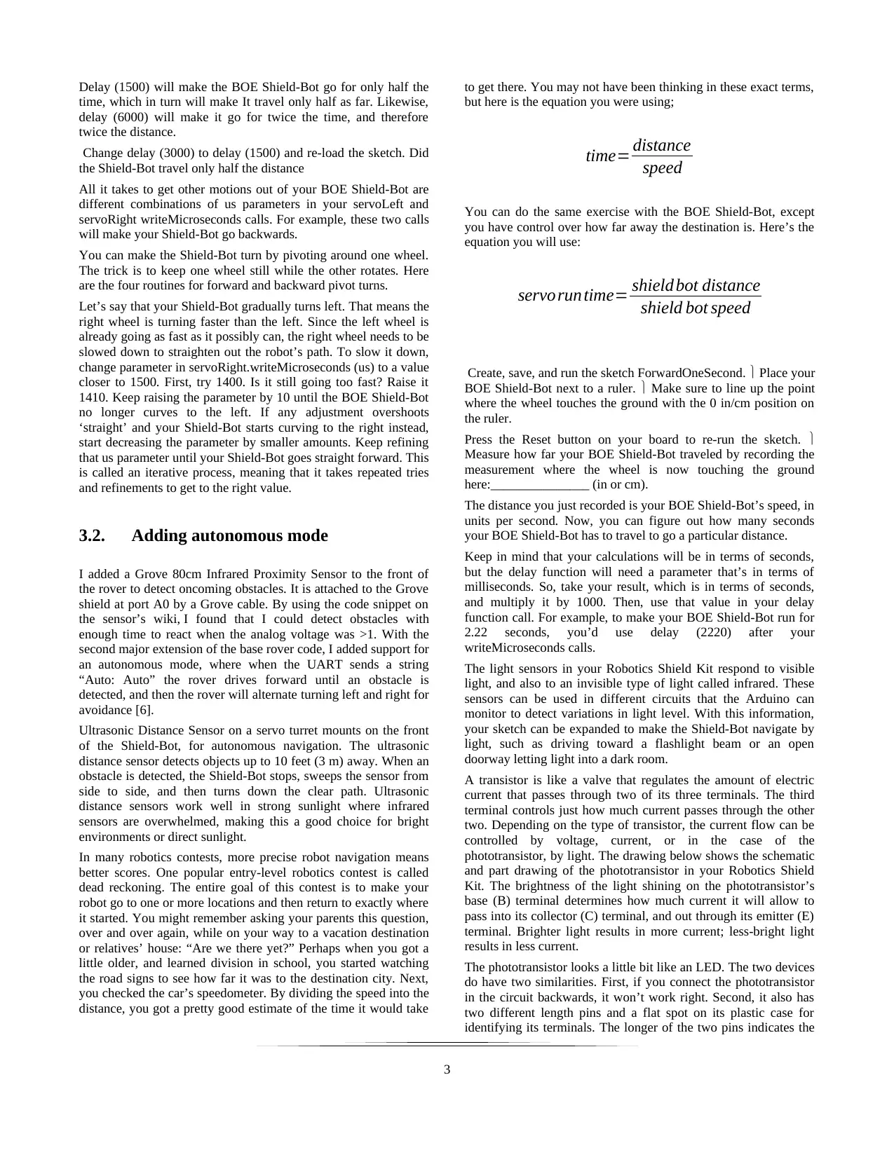
Mounting the Acrylic Plate and Add Sensors – Secure the acrylic
plate to the main chassis using the four brass connectors. Connect
the Grove LED to Grove Shield port D2.
Figure 3: The sensor
Mounting the Aluminum Plate – Secure the aluminum mounting
plate on top of the acrylic. Installing the wheels – Install the 4
wheels onto the drive shaft mounting plate using the screw.
The shield-Bot has some features which include; Easy to start:
The ShieldBot is plug & play, so can be ready to use within a few
minutes; Expandable: solderless grove expansion ports enable
easy attachment of more sensors, and shield headers allow the use
of additional Arduino shields; Open Source: Its designed to be
modified, adapted and transformed into whatever you want, and
Arduino Based: The ShieldBot is an Arduino shield, so the
extensive Arduino community and shield ecosystem will make
your project ideas limitless!
3.1. Programming the Shield-Bot
Connect the DC barrel jack to the Arduino 101. Connect the Li-Po
battery to the Dean’s male Traxxas connection. Connect a USB
programming cable to the Arduino 101 and to your computer.
I use the same Arduino101 and Grove Motor Controller as
the Programming the Arduino101 for a basic rover so check it out
for an overview of how BLE is setup, and the motors are
controlled using the Grove Motor Controller. Since the original
base model code used one motor controller, and two are used
here, there are some basic changes that I had to make.
However, the first major extension that I added was to process the
whole UART transmitted string instead just the first character.
This allows the commands between the rover and the BLE mobile
device to be more human readable. For example, “a” go forward
became: “Auto: Up” and “b” turn left became: “Auto: Left” [5].
To make the BOE Shield-Bot go forward, its left wheel has to turn
counterclockwise, but its right wheel has to turn clockwise.
Remember that a sketch can use the Servo library’s write
Microseconds function to control the speed and direction of each
servo. Then, it can use the delay function to keep the servos
running for certain amounts of time before choosing new speeds
and directions. Here’s an example that will make the BOE Shield-
Bot roll forward for about three seconds, and then stop. Example
Sketch: Forward ThreeSeconds Make sure the BOE Shield’s
power switch is set to 1 and the battery pack is plugged into the
Arduino. Create and save the ForwardThreeSeconds sketch, and
run it on the Arduino. Disconnect the programing cable and put
the BOE Shield-Bot on the floor. While holding down the Reset
button, move the switch to position 3, and then let go. The BOE
Shield-Bot should drive forward for three seconds.
A sketch automatically starts in its setup function. It runs the code
in there once before moving on to the loop function, which
automatically keeps repeating. Since we only want the BOE
Shield-Bot to go forward and stop once, all the code can be placed
in the setup function. This leaves the loop function empty, but
that’s okay. Chapter 4 • BOE Shield-Bot Navigation 106 •
Robotics with the BOE Shield-Bot As with all motion sketches,
the first action setup takes is making the piezospeaker beep. The
tone function call transmits a signal to digital pin 4 that makes the
piezospeaker play a 3 kHz tone that lasts for 1 second. Since the
tone function works in the background while the code moves on,
delay (1000) prevents the BOE Shield-Bot from moving until the
tone is done playing
Next, the servoLeft object instance gets attached to digital pin 13
and the servoRight instance gets attached to pin 12. This makes
calls to servoLeft.writeMicroseconds affect the servo control
signals sent on pin 13. Likewise, servoRight.writeMicroseconds
calls will affect the signals sent on pin 12.
Remember that we need the BOE Shield-Bot’s left and right
wheels to turn in opposite directions to drive forward. The
function call servoLeft.writeMicroseconds (1700) makes the left
servo turn full speed counterclockwise, and the function call
servoRight.writeMicroseconds (1300) makes the right wheel turn
full speed clockwise. The result is forward motion. The delay
(3000) function call keeps the servos running at that speed for
three full seconds. After the delay, servoLeft.detach and
servoRight.detach discontinue the servo signals, which bring the
robot to a stop
After the setup function runs out of code, the sketch automatically
advances to the loop function, which repeats itself indefinitely. In
this case, we are leaving it empty because the sketch is done, so it
repeWant to change the distance traveled? Just change the time in
delay (3000). For example,
2
Wire power cables – Wire the power cables to the motor
controllers (red is positive, black is negative). Make sure to
tighten all terminals to prevent wires from disconnecting [4].
Installing the Grove Shield – Insert the Grove shield onto the
Arduino breakout board. Connect the motor controllers to the
Grove Shield in any I2C labelled port using the Grove cables.
Mounting the Acrylic Plate and Add Sensors – Secure the acrylic
plate to the main chassis using the four brass connectors. Connect
the Grove LED to Grove Shield port D2.
Figure 3: The sensor
Mounting the Aluminum Plate – Secure the aluminum mounting
plate on top of the acrylic. Installing the wheels – Install the 4
wheels onto the drive shaft mounting plate using the screw.
The shield-Bot has some features which include; Easy to start:
The ShieldBot is plug & play, so can be ready to use within a few
minutes; Expandable: solderless grove expansion ports enable
easy attachment of more sensors, and shield headers allow the use
of additional Arduino shields; Open Source: Its designed to be
modified, adapted and transformed into whatever you want, and
Arduino Based: The ShieldBot is an Arduino shield, so the
extensive Arduino community and shield ecosystem will make
your project ideas limitless!
3.1. Programming the Shield-Bot
Connect the DC barrel jack to the Arduino 101. Connect the Li-Po
battery to the Dean’s male Traxxas connection. Connect a USB
programming cable to the Arduino 101 and to your computer.
I use the same Arduino101 and Grove Motor Controller as
the Programming the Arduino101 for a basic rover so check it out
for an overview of how BLE is setup, and the motors are
controlled using the Grove Motor Controller. Since the original
base model code used one motor controller, and two are used
here, there are some basic changes that I had to make.
However, the first major extension that I added was to process the
whole UART transmitted string instead just the first character.
This allows the commands between the rover and the BLE mobile
device to be more human readable. For example, “a” go forward
became: “Auto: Up” and “b” turn left became: “Auto: Left” [5].
To make the BOE Shield-Bot go forward, its left wheel has to turn
counterclockwise, but its right wheel has to turn clockwise.
Remember that a sketch can use the Servo library’s write
Microseconds function to control the speed and direction of each
servo. Then, it can use the delay function to keep the servos
running for certain amounts of time before choosing new speeds
and directions. Here’s an example that will make the BOE Shield-
Bot roll forward for about three seconds, and then stop. Example
Sketch: Forward ThreeSeconds Make sure the BOE Shield’s
power switch is set to 1 and the battery pack is plugged into the
Arduino. Create and save the ForwardThreeSeconds sketch, and
run it on the Arduino. Disconnect the programing cable and put
the BOE Shield-Bot on the floor. While holding down the Reset
button, move the switch to position 3, and then let go. The BOE
Shield-Bot should drive forward for three seconds.
A sketch automatically starts in its setup function. It runs the code
in there once before moving on to the loop function, which
automatically keeps repeating. Since we only want the BOE
Shield-Bot to go forward and stop once, all the code can be placed
in the setup function. This leaves the loop function empty, but
that’s okay. Chapter 4 • BOE Shield-Bot Navigation 106 •
Robotics with the BOE Shield-Bot As with all motion sketches,
the first action setup takes is making the piezospeaker beep. The
tone function call transmits a signal to digital pin 4 that makes the
piezospeaker play a 3 kHz tone that lasts for 1 second. Since the
tone function works in the background while the code moves on,
delay (1000) prevents the BOE Shield-Bot from moving until the
tone is done playing
Next, the servoLeft object instance gets attached to digital pin 13
and the servoRight instance gets attached to pin 12. This makes
calls to servoLeft.writeMicroseconds affect the servo control
signals sent on pin 13. Likewise, servoRight.writeMicroseconds
calls will affect the signals sent on pin 12.
Remember that we need the BOE Shield-Bot’s left and right
wheels to turn in opposite directions to drive forward. The
function call servoLeft.writeMicroseconds (1700) makes the left
servo turn full speed counterclockwise, and the function call
servoRight.writeMicroseconds (1300) makes the right wheel turn
full speed clockwise. The result is forward motion. The delay
(3000) function call keeps the servos running at that speed for
three full seconds. After the delay, servoLeft.detach and
servoRight.detach discontinue the servo signals, which bring the
robot to a stop
After the setup function runs out of code, the sketch automatically
advances to the loop function, which repeats itself indefinitely. In
this case, we are leaving it empty because the sketch is done, so it
repeWant to change the distance traveled? Just change the time in
delay (3000). For example,
2
Delay (1500) will make the BOE Shield-Bot go for only half the
time, which in turn will make It travel only half as far. Likewise,
delay (6000) will make it go for twice the time, and therefore
twice the distance.
Change delay (3000) to delay (1500) and re-load the sketch. Did
the Shield-Bot travel only half the distance
All it takes to get other motions out of your BOE Shield-Bot are
different combinations of us parameters in your servoLeft and
servoRight writeMicroseconds calls. For example, these two calls
will make your Shield-Bot go backwards.
You can make the Shield-Bot turn by pivoting around one wheel.
The trick is to keep one wheel still while the other rotates. Here
are the four routines for forward and backward pivot turns.
Let’s say that your Shield-Bot gradually turns left. That means the
right wheel is turning faster than the left. Since the left wheel is
already going as fast as it possibly can, the right wheel needs to be
slowed down to straighten out the robot’s path. To slow it down,
change parameter in servoRight.writeMicroseconds (us) to a value
closer to 1500. First, try 1400. Is it still going too fast? Raise it
1410. Keep raising the parameter by 10 until the BOE Shield-Bot
no longer curves to the left. If any adjustment overshoots
‘straight’ and your Shield-Bot starts curving to the right instead,
start decreasing the parameter by smaller amounts. Keep refining
that us parameter until your Shield-Bot goes straight forward. This
is called an iterative process, meaning that it takes repeated tries
and refinements to get to the right value.
3.2. Adding autonomous mode
I added a Grove 80cm Infrared Proximity Sensor to the front of
the rover to detect oncoming obstacles. It is attached to the Grove
shield at port A0 by a Grove cable. By using the code snippet on
the sensor’s wiki, I found that I could detect obstacles with
enough time to react when the analog voltage was >1. With the
second major extension of the base rover code, I added support for
an autonomous mode, where when the UART sends a string
“Auto: Auto” the rover drives forward until an obstacle is
detected, and then the rover will alternate turning left and right for
avoidance [6].
Ultrasonic Distance Sensor on a servo turret mounts on the front
of the Shield-Bot, for autonomous navigation. The ultrasonic
distance sensor detects objects up to 10 feet (3 m) away. When an
obstacle is detected, the Shield-Bot stops, sweeps the sensor from
side to side, and then turns down the clear path. Ultrasonic
distance sensors work well in strong sunlight where infrared
sensors are overwhelmed, making this a good choice for bright
environments or direct sunlight.
In many robotics contests, more precise robot navigation means
better scores. One popular entry-level robotics contest is called
dead reckoning. The entire goal of this contest is to make your
robot go to one or more locations and then return to exactly where
it started. You might remember asking your parents this question,
over and over again, while on your way to a vacation destination
or relatives’ house: “Are we there yet?” Perhaps when you got a
little older, and learned division in school, you started watching
the road signs to see how far it was to the destination city. Next,
you checked the car’s speedometer. By dividing the speed into the
distance, you got a pretty good estimate of the time it would take
to get there. You may not have been thinking in these exact terms,
but here is the equation you were using;
time= distance
speed
You can do the same exercise with the BOE Shield-Bot, except
you have control over how far away the destination is. Here’s the
equation you will use:
servorun time= shield bot distance
shield bot speed
Create, save, and run the sketch ForwardOneSecond. Place your
BOE Shield-Bot next to a ruler. Make sure to line up the point
where the wheel touches the ground with the 0 in/cm position on
the ruler.
Press the Reset button on your board to re-run the sketch.
Measure how far your BOE Shield-Bot traveled by recording the
measurement where the wheel is now touching the ground
here:_______________ (in or cm).
The distance you just recorded is your BOE Shield-Bot’s speed, in
units per second. Now, you can figure out how many seconds
your BOE Shield-Bot has to travel to go a particular distance.
Keep in mind that your calculations will be in terms of seconds,
but the delay function will need a parameter that’s in terms of
milliseconds. So, take your result, which is in terms of seconds,
and multiply it by 1000. Then, use that value in your delay
function call. For example, to make your BOE Shield-Bot run for
2.22 seconds, you’d use delay (2220) after your
writeMicroseconds calls.
The light sensors in your Robotics Shield Kit respond to visible
light, and also to an invisible type of light called infrared. These
sensors can be used in different circuits that the Arduino can
monitor to detect variations in light level. With this information,
your sketch can be expanded to make the Shield-Bot navigate by
light, such as driving toward a flashlight beam or an open
doorway letting light into a dark room.
A transistor is like a valve that regulates the amount of electric
current that passes through two of its three terminals. The third
terminal controls just how much current passes through the other
two. Depending on the type of transistor, the current flow can be
controlled by voltage, current, or in the case of the
phototransistor, by light. The drawing below shows the schematic
and part drawing of the phototransistor in your Robotics Shield
Kit. The brightness of the light shining on the phototransistor’s
base (B) terminal determines how much current it will allow to
pass into its collector (C) terminal, and out through its emitter (E)
terminal. Brighter light results in more current; less-bright light
results in less current.
The phototransistor looks a little bit like an LED. The two devices
do have two similarities. First, if you connect the phototransistor
in the circuit backwards, it won’t work right. Second, it also has
two different length pins and a flat spot on its plastic case for
identifying its terminals. The longer of the two pins indicates the
3
⊘ This is a preview!⊘
Do you want full access?
Subscribe today to unlock all pages.
Trusted by 1+ million students worldwide
phototransistor’s collector terminal. The shorter pin indicates the
emitter, and it connects closer to a flat spot on the
phototransistor’s clear plastic case.
Your robot’s final task in the course is to stop underneath that
bright light. There’s a simple phototransistor circuit you can use
that lets the Arduino know it detected bright light with a binary-1,
or ambient light with a binary-0. Incandescent bulbs in desk lamps
and flashlights make the best bright-light sources. Compact
fluorescent and LED light sources are not as easy for the circuit in
this activity to recognize.
The Shield-Bot can already use whiskers to get around, but it only
detects obstacles when it bumps into them. Wouldn’t it be
convenient if the Shield-Bot could just “see” objects and then
decide what to do about them? Well, that’s what it can do with
infrared headlights and eyes like the ones shown below. Each
headlight is an infrared LED inside a tube that directs the light
forward, just like a flashlight. Each eye is an infrared receiver that
sends the Arduino high/low signals to indicate whether it detects
the infrared LED’s light reflected off an object.
Infrared is abbreviated IR, and it is light the human eye cannot
detect (for a color image of the visible light spectrum. The IR
LEDs introduced in this chapter emit infrared light, just like the
red LEDs we’ve been using emit visible light. The infrared
receivers in this chapter detect infrared light, similar to the
phototransistors in the last chapter. But, there’s a difference—
these infrared receivers are not just detecting ambient light, but
they are designed to detect infrared light flashing on and off very
quickly. The infrared LED that the BOE Shield-Bot will use as a
tiny headlight is actually the same kind you can find in just about
any TV remote. The TV remote flashes the IR LED to send
messages to your TV. The microcontroller in your TV picks up
those messages with an infrared receiver like the one your Shield-
Bot will use.
The next figures show the IR object detection schematic and
wiring diagram. One IR object detector (IR LED and receiver
pair) is mounted on each corner of the breadboard closest to the
very front of the Shield-Bot. Disconnect the power and
programming cables. Build the circuit in the schematic below,
using the wiring diagram as a reference for parts placement. Note
that the anode lead of each IR LED connects to a 2 kΩ resistor.
The cathode lead plugs into the same breadboard row as an IR
detector’s center pin, and that row is connected to GND with a
jumper wire.
This sketch only tests the BOE Shield-Bot’s left IR detector. This
helps simplify troubleshooting because you are focusing on only
one of the two circuits. This is yet another example of subsystem
testing. After the subsystems check out, we can move to system
integration. But first, you’ve got to make sure to test and correct
any wiring or code entry errors that might have crept in.
Reconnect the battery pack to the Arduino. Set the 3-position
switch to position 1. Create, save, and run the sketch the sketch
TestLeftIr.
Place an object, such as your hand or a sheet of paper, about an
inch (2 to 3 cm) from the left IR object detector. Verify that the
Serial Monitor displays a 0 when you place an object in front of
the IR object detector, and a 1 when you remove the object. If
the Serial Monitor displays the expected values, go ahead and test
the right IR Object Detector (below). If not, go to the
Troubleshooting section for help.
3.3. Problem Analysis
The following issues were encountered in the design and
execution stages:
The Activity Bot calibration routine went fine, but instead of
driving straight, it drives in a jerky, wavy line.
My Activity Bot completed the calibration, but one or both wheels
continue to turn when it is supposed to be stopped.
The Activity Bot is on and receiving power, but will not move
when programmed, or resets itself while running.
The Activity Bot servos and encoders are powered when the 3-
position switch is in position 1.
When the Activity Bot is connected to the computer via USB
cable, no COM port registers for it and/or the computer displays
an error (no board detected, or board may not be working
properly).
The Activity Bot moves in the opposite direction from what it was
programmed to do.
3.4. Research
The shield-bot uses infrared proximity sensors to detect the line
and distance (which is 200 centimeters) and on the basis of input
received from the sensors, the Arduino will direct the motor to
move with the help of a motor shield.
The shield robot usually works by using the infra-red sensors
placed on the front. There are four expected results from the
sensors, namely;
Case 1:- In this case, both the sensors don't detect the
line/path. Both the motors rotate forward. As a result, the shield-
bot moves forward.
Case 2:- In this case, only the left sensor detects the line
which means that the car requires to turn in the left direction. The
left motor rotates backward and the right motor rotates forward.
As a result, the shield-bot turns left.
Case 3:- In this case, only the right sensor detects the line
which means that the car requires to turn in the right direction.
The left motor rotates forward and the right motor rotates
backward. As a result, the shield-bot turns right.
Case 4:- In this case, both the sensors detect the line. This
means that the end has come. Both the motors stop rotating. As a
result, the shield-bot stops.
In the case where we choose to use the ultrasonic sensors in
place of IR sensors, the sensors are mounted on the front of the
shield-bot. The ultrasonic distance sensor are set to detect objects
up to 2 meters away after the Arduino activates the turning of the
shield bot by 180 degrees. When an obstacle is detected, the
Shield-Bot stops, sweeps the sensor from side to side, and then
turns down the clear path.
Ultrasonic sensors work by emitting sound waves with a
frequency that is too high for a human to hear. These sound waves
travel through the air with the speed of sound, roughly 343 m/s. If
there is an object in front of the sensor, the sound waves get
reflected back and the receiver of the ultrasonic sensor detects
them. By measuring how much time passed between sending and
receiving the sound waves, the distance between the sensor and
the object can be calculated.
4
Paraphrase This Document
Need a fresh take? Get an instant paraphrase of this document with our AI Paraphraser
At 20°C the speed of sound is roughly 343 m/s or 0.034
cm/μs. Let’s say that the time between sending and receiving the
sound waves is 2000 microseconds. If you multiply the speed of
sound by the time the sound waves traveled, you get the distance
that the sound waves traveled.
Distance = Speed x Time
But that is not the result we are looking for. The distance
between the sensor and the object is actually only half this
distance because the sound waves traveled from the sensor to the
object and back from the object to the sensor. So you need to
divide the result by two.
Distance (cm) = Speed of sound (cm/μs) × Time (μs) / 2
And so for the example this becomes:
Distance (cm) = 0.0343 (cm/μs) × 2000 (μs) / 2 = 34.3 cm
The BOE Shield-Bot can already use whiskers to get around, but
it only detects obstacles when it bumps into them. Wouldn’t it be
better if the BOE Shield-Bot could just “see” objects and then
decide what to do about them? Well, that’s what it can do with
infrared headlights and eyes like the ones shown below. Each
headlight is an infrared LED inside a tube that directs the light
forward, just like a flashlight. Each eye is an infrared receiver
that sends the Arduino high/low signals to indicate whether it
detects the infrared LED’s light reflected off an object.
4. PROBLEM SOLUTION
The following were remedies to the problems we faced:
You may need to adjust the servo or servo bracket. Check the
position of the servo inside its hole in the chassis. Notice that
there is a little bit of space around the servo. If the servo is tight
against the top edge of the hole close to the encoder, with a gap
left below the servo, the beam of infrared light coming from the
encoder sensor might be missing the wheel spokes and hitting the
solid ring below them instead [7].
You must re-run the calibration program once you perform
manual calibration – do not forget to do this!
Your servos may be manually uncentered beyond what the
calibration program can compensate for. Try running the
following code (by opening a new project), and using a small
screwdriver to very gently turn the potentiometer in the small hole
in the back of your affected servo until the wheel stops spinning.
First, if the servos do not turn at all, make sure the power switch is
in Position 2 (which powers the servo headers), and not Position
1. If that doesn't help, check the batteries. Low batteries or
batteries that are placed in backward will not provide enough
power to the ActivityBot to run all of its components effectively.
This can result in slower speeds, resets, or loss of functionality.
First, if the servos do not turn at all, make sure the power switch is
in Position 2 (which powers the servo headers), and not Position
1. If that doesn't help, check the servo port jumper positions. The
jumper for P12 and P13 should be set to VIN — if it is set to 5V
the servos will not receive enough power. Follow the Electrical
Connections page instructions for moving the jumper, and then
run the calibration again.
Potentially, a short circuit has damaged your Activity Board
(original or WX version). Position 1 on the 3-position switch
should not power the 3-pin headers above the breadboard that the
servos and encoders are plugged into. This problem can often be
caused if the shunt jumper for P12 & P13 was moved while the
Activity Board (original or WX version) was receiving power
from the USB port or barrel jack. Unfortunately, there is no
solution for this problem once it has occurred, please contact
technical support.
Check the USB connection on the Activity Board (original or WX
version). The USB connection port on the ActivityBot is
designed to fit tightly to the Mini B connector. Even though it
may feel secure, sometimes the cable may not be inserted fully
into the port, and this will cause your computer not to recognize
the connection or give an error.
Check your servo cables. A common mistake is to accidently
switch the cables for left and right servos, which causes the
ActivityBot to go backwards when it should go forward, left when
it should go right, etc. Check to make sure the left and right
connections match the Electrical Connections page instructions,
and then run the calibration again [8].
Issue: The calibration table display shows null values, or values
that alternate from high numbers to low numbers quickly
(repeating 161 - 0, for example).
Solution: The encoder IR sensor may not be functioning
correctly. Check the encoder cable plug on both ends to make sure
it is seated properly. Re-run the calibration a second time and
check the interpolation table again using the Display Calibration
program. If there is no change, please get in touch with Technical
Support using the contact information above. There is no fix for a
malfunctioning encoder; it may need to be replaced.
Issue: The ActivityBot appears to run the calibration routine, but
it takes a long time. When I tried to look at the calibration with
ActivityBot Calibration Display.side, the SimpleIDE terminal was
blank.
Solution: First, check to make sure the resistors connecting P14
and P15 to 3.3 V are marked red-black-orange (20 k-ohm). Next,
check to make sure your encoder cables are not plugged into the
3-pin headers upside down. White wire should be near the top
edge of the board, black wire should be near the 5V labels.
5. TESTING AND VERIFICATION
The shield-bot should be able to perform various functions
including; Monitor sensors to detect the world around it, Make
decisions based on what it senses, Control its motion (by
operating the motors that make its wheels turn), and Exchange
information with its roboticist (that will be you!)
There were three tests in different surface. 1. Smooth surface 2.
Uphill 3. Downhill.
5
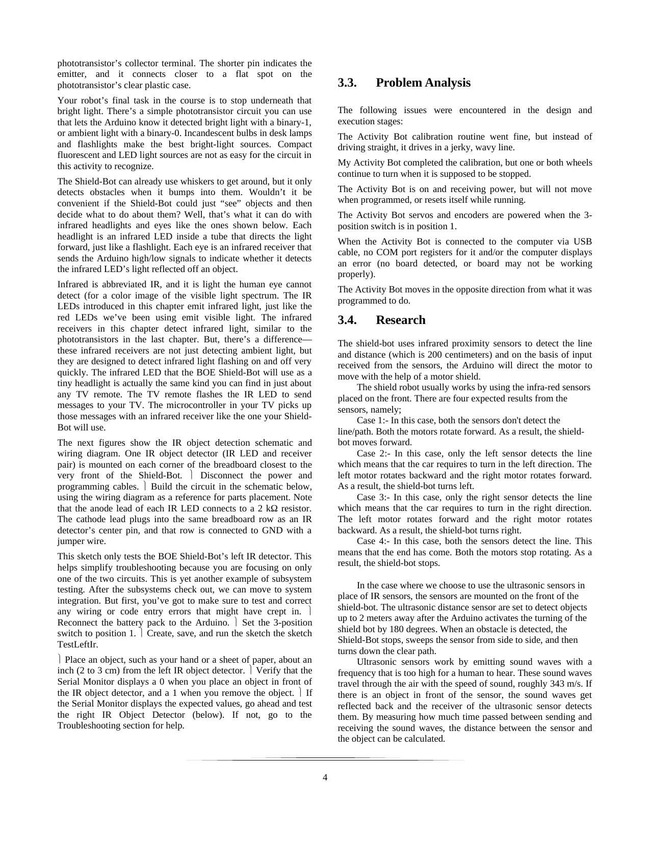
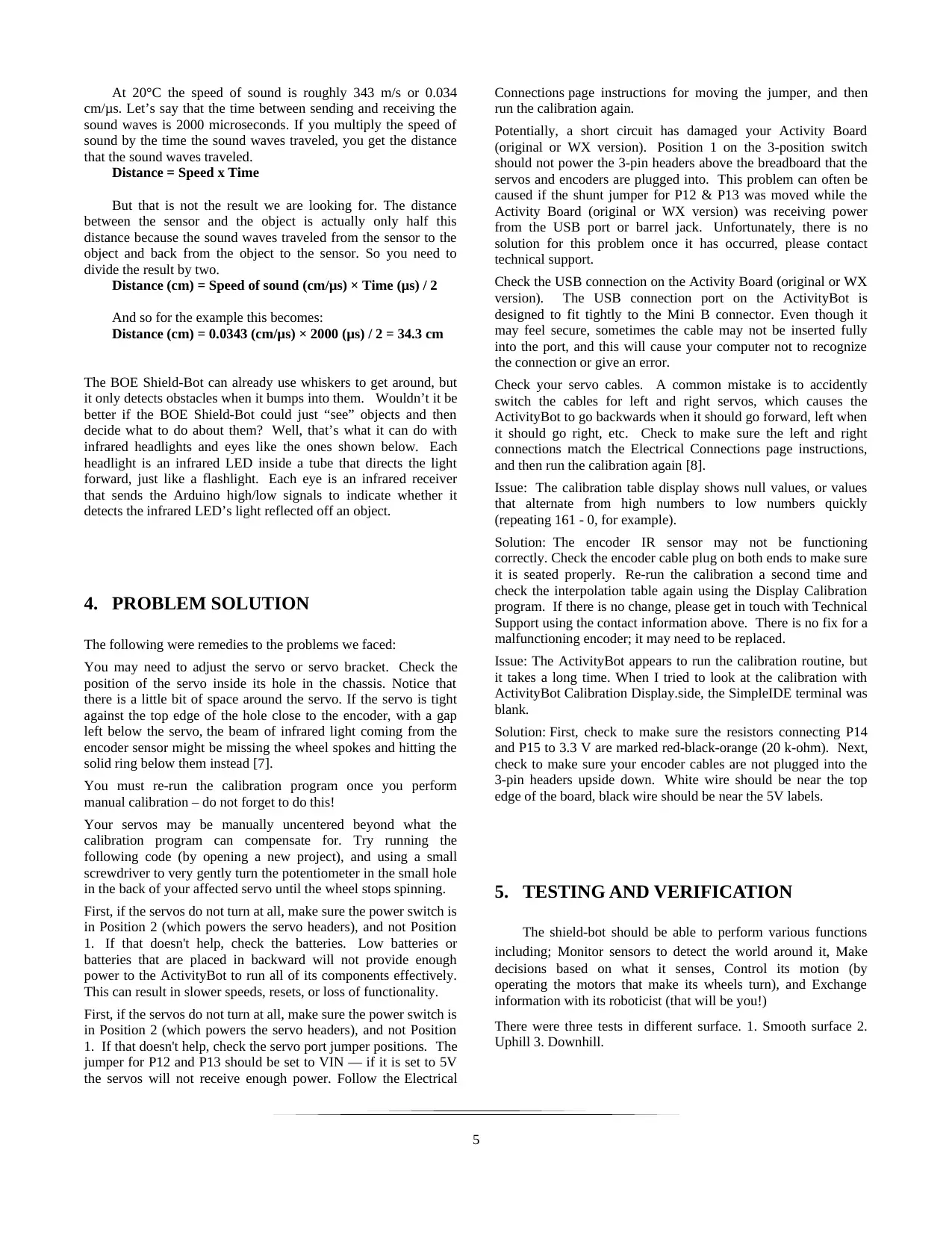
Figure 4: The shield-Bot on floor
5.1. Testing the shield-bot on a normal floor
Testing the Frequency Sweep Here's a graph from one specific
brand of IR detector’s datasheet (Panasonic PNA4602M; a
different brand may have been used in your kit). The graph shows
that the IR detector is most sensitive at 38 kHz—its peak
sensitivity —at the top of the curve. Notice how quickly the curve
drops on both sides of the peak. This IR detector is much less
sensitive to IR signals that flash on/off at frequencies other than
38 kHz. It’s only half as sensitive to an IR LED flashing at 40
kHz as it would be to 38 kHz signals. For an IR LED flashing at
42 kHz, the detector is only 20% as sensitive. The further from 38
kHz an IR LED’s signal rate is, the closer the IR receiver has to
be to an object to see that IR signal’s reflection [9].
5.2. Testing the shield-bot on a downhill
floor
The most sensitive frequency (38 kHz) will detect the objects that
are the farthest away, while less-sensitive frequencies can only
detect closer objects. This makes rough distance detection rather
simple: pick some frequencies, then test them from most sensitive
to least sensitive. Try the most sensitive frequency first. If an
object is detected, check and see if the next-most sensitive
frequency detects it. Depending on which frequency makes the
reflected infrared no longer visible to the IR detector, your sketch
can infer a rough distance. Programming Frequency Sweep for
Distance Detection The next diagram shows an example of how
the BOE Shield-Bot can test for distance using frequency. Note
this diagram is not to scale: the detection range only covers a short
distance, and begins a few centimeters away from the robot [10].
5.3. Testing the shield-bot on uphill floor
When a machine is designed to automatically maintain a
measured value, it generally involves a control system. The value
that the system is trying to maintain is called the set point.
Electronic control systems often use a processor to take sensor
measurements and respond by triggering mechanical actuators to
return the machine to the set point [11].
Our machine is the BOE Shield-Bot. The measured value we want
it to maintain is the distance to the leader-object, with a set point
of 2. The machine’s processor is the Arduino. The IR
LED/receiver pairs are the sensors that take distance value
measurements to the leader-object. If the measured distance is
different from the set-point distance, the servos are the mechanical
actuators that rotate to move the BOE Shield-Bot forward or
backward as needed [12].
6. CONCLUSIONS
This article explains the design, evaluation and testing of the
Arduino shield-bot. The main objective of this challenge was to
test the ability of the shield-bot to drive straight in various
surfaces of the floor. All the tests done were positive despite a
few problems encountered in the execution stage of this process.
It is proved that the shield when installed with motion and
distance sensors such as IR or ultrasonic packed with correctly
coded Arduino software can perform various activities
autonomously and can make about turns of 180o and return to its
initial position.
Various problems encountered can be dealt with in the designing
and programming stage.
Future tests are required to be done on various weak areas such as
the use of ultrasonic sensor instead of IR sensor, use of four wheel
and other important adjustments and developments. For instance,
tactile switches are also called bumper switches or touch switches,
and they have many uses in robotics. A robot programmed to
pick up an object and move it to another conveyer belt might rely
on a tactile switch to detect the object. Automated factory lines
might use tactile switches to count objects, and to align parts for a
certain step in a manufacturing process. In each case, switches
provide inputs that trigger some form of programmed output. The
inputs are electronically monitored by the equipment’s processor,
which takes different actions depending on if the switch is pressed
or not pressed.
6
⊘ This is a preview!⊘
Do you want full access?
Subscribe today to unlock all pages.
Trusted by 1+ million students worldwide
7. REFERENCES
[1] M. Margolis, Make an Arduino-Controlled Robot, 1st ed., Beijing: O'Reilly Media, Inc., 2012.
[2] D. M. N. K. Dr Paul Griffiths, ECIAIR 2019 European Conference on the Impact of Artificial Intelligence and Robotics,
Reading: Academic Conferences and publishing limited, 2019.
[3] A. G. Araújo, ROSint - Integration of a mobile robot in ROS architecture, Lisbon: University of Coimbra, 2012.
[4] G. McComb, Arduino Robot Bonanza, New York: McGraw Hill Professional, 2013.
[5] J. Baichtal, Robot Builder: The Beginner's Guide to Building Robots, 1st ed., Indianapolis: Que Publishing, 2014.
[6] J. A. H. M. John-David Warren, Arduino Robotics, 1st ed., New York: Apress, 2011.
[7] M. B. A. W. John Baichtal, Make: Lego and Arduino Projects: Projects for Extending MINDSTORMS NXT with Open-source
Electronics, 2nd ed., New York: O'Reilly Media, Inc., 2012.
[8] B. Huang, The Arduino Inventor's Guide: Learn Electronics by Making 10 Awesome Projects, 1st ed., San Francisco: No Starch
Press, 2017.
[9] G. Borenstein, Making Things See: 3D Vision with Kinect, Processing, Arduino, and MakerBot, 1st ed., Sebastopol: O'Reilly
Media, Inc, 2012.
[10] J. Lazar, Arduino and LEGO Projects, 1st ed., New York: Apress, 2013.
[11] J. Cicolani, Beginning Robotics with Raspberry Pi and Arduino: Using Python and OpenCV, 1st ed., New York: Apress, 2018.
[12] J. Boxall, Arduino Workshop: A Hands-on Introduction with 65 Projects, San Francisco: No Starch Press, 2013.
[13] G. Schliwa, R. Armitage, S. Aziz, J. Evans and J. Rhoades, "Sustainable city logistics—Making cargo cycles viable for urban
freight transport," Research in Transportation Business & Management, vol. 1, no. 15, pp. 50-57, 2015.
[14] E. Burnette, Hello, Android: Introducing Google's Mobile Development Platform, Amsterdam: Pragmatic Bookshelf, 2015.
7
1 out of 7
Your All-in-One AI-Powered Toolkit for Academic Success.
+13062052269
info@desklib.com
Available 24*7 on WhatsApp / Email
![[object Object]](/_next/static/media/star-bottom.7253800d.svg)
Unlock your academic potential
Copyright © 2020–2026 A2Z Services. All Rights Reserved. Developed and managed by ZUCOL.