Collin's ATM System: Use Case, Class & Sequence Diagrams Project
VerifiedAdded on 2024/06/03
|19
|2366
|225
Project
AI Summary
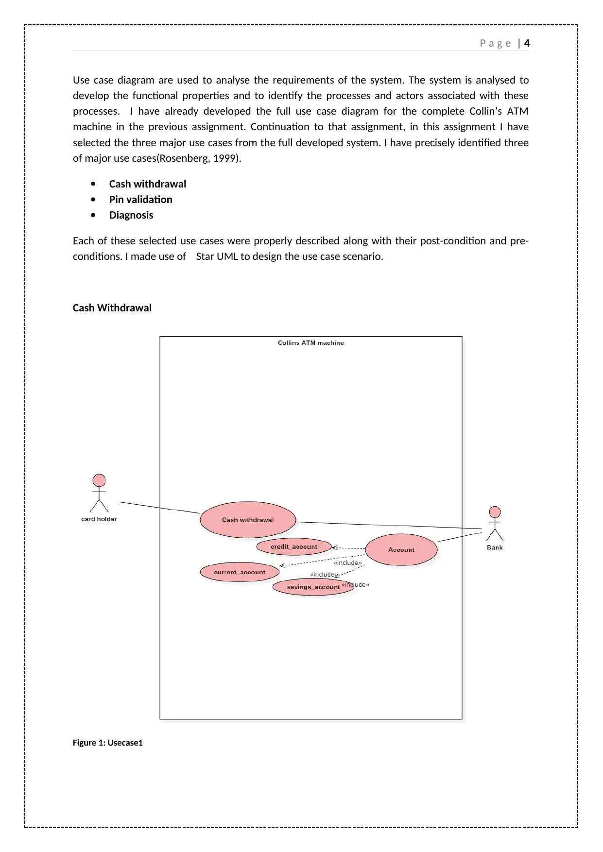
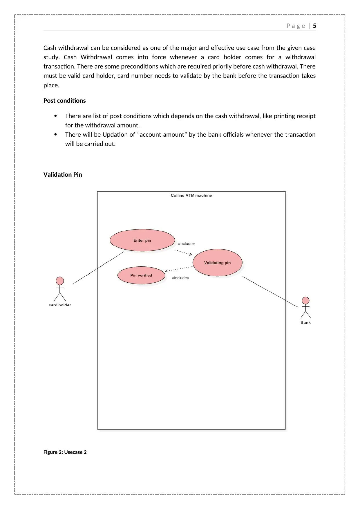
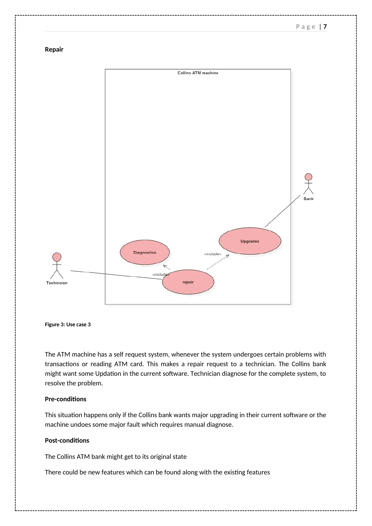
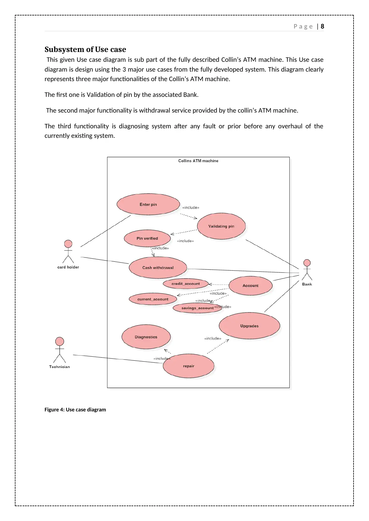
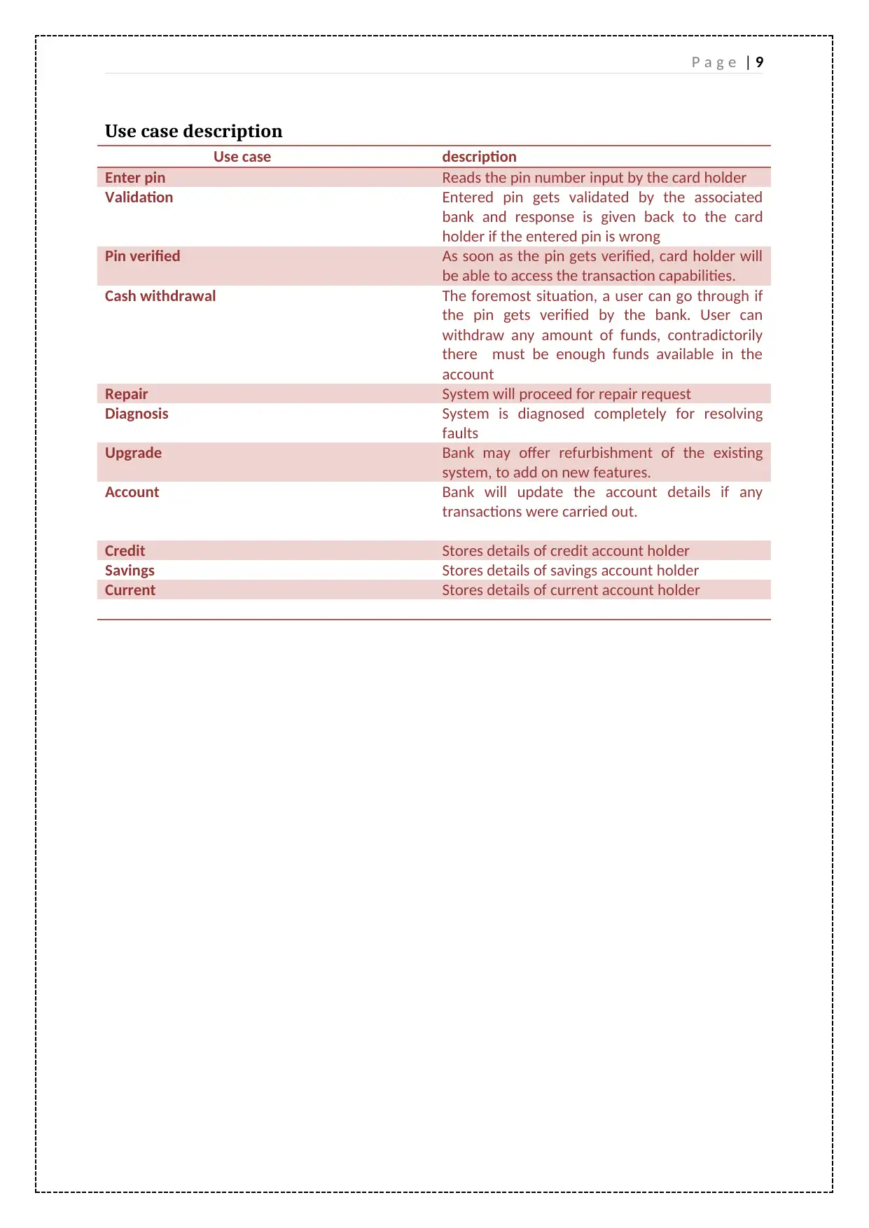
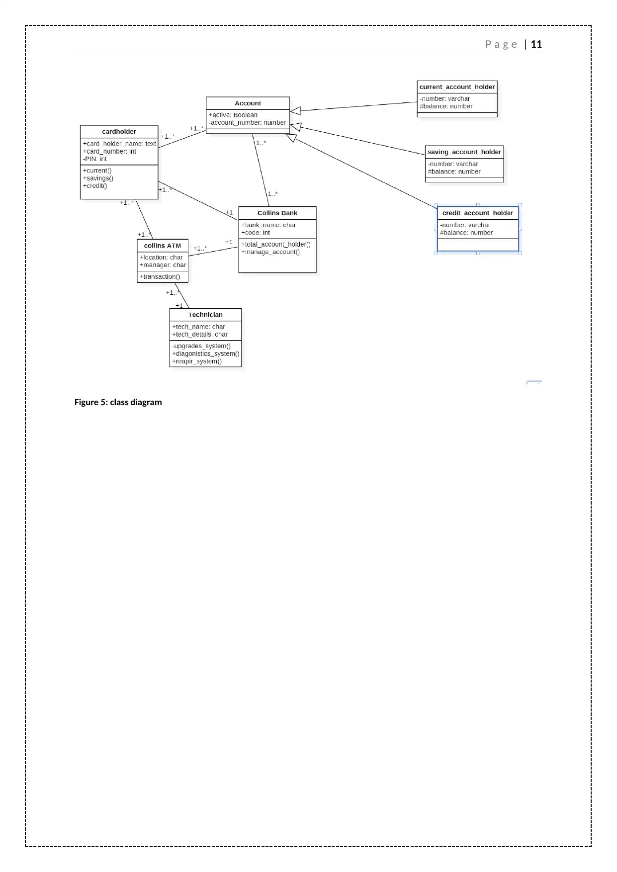
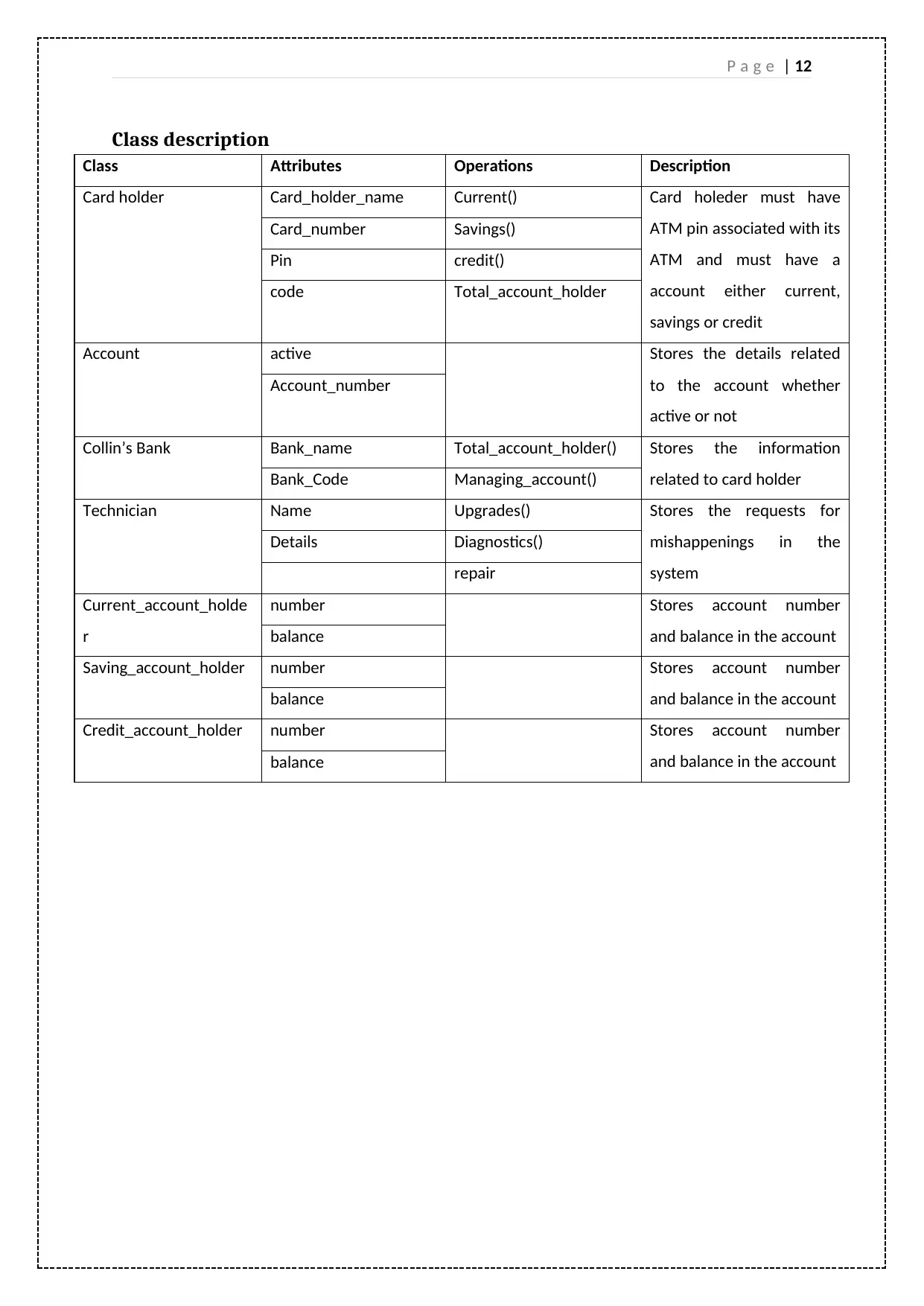
This project assignment focuses on the design and analysis of an ATM system, specifically Collin's ATM machine, using UML diagrams. The project selects three major use cases: cash withdrawal, PIN validation, and system diagnosis, each described with preconditions and post-conditions. A subsystem diagram is designed to represent the ATM's functionalities, followed by a corresponding class diagram detailing the classes, attributes, operations, and their relationships. Sequence diagrams are then developed for each use case to illustrate the interactions between objects during the respective processes, providing a clear understanding of the system's behavior. The assignment concludes by reflecting on the usefulness of these UML models and their contribution to understanding object interactions.

P a g e | 1
Table of Contents
Introduction...........................................................................................................................................2
Use Case diagram..................................................................................................................................3
Subsystem of Use case......................................................................................................................7
Use case description..........................................................................................................................8
Class diagram.........................................................................................................................................9
Class description..............................................................................................................................11
Sequence diagram...............................................................................................................................12
Conclusion...........................................................................................................................................17
References...........................................................................................................................................18
List of figures
Figure 1: Usecase1.................................................................................................................................2
Figure 2: Usecase 2................................................................................................................................3
Figure 3: Use case 3...............................................................................................................................5
Figure 4: Use case diagram....................................................................................................................6
Figure 5: class diagram..........................................................................................................................8
Figure 6: sequence diagram for usecase validation.............................................................................10
Figure 7: Sequence diagram for withdrawal........................................................................................11
Figure 8: sequence diagram for diagnosis...........................................................................................12
Paraphrase This Document
Need a fresh take? Get an instant paraphrase of this document with our AI Paraphraser

P a g e | 2
Introduction
In this assignment I made selection for three major use cases from previously developed full system
development of Collin’s ATM machine. These uses cases have been precisely chosen and their pre-
conditions and Post-conditions are explained. I have designed a subsystem diagram along with its
description. Depending on the designed subsystem I have designed the associated class diagram for
the subsystem. I took care of all the attributes and operations and their cardinalities. I have
developed sequence diagram for each of the use case selected. This communication diagram will
help in letting know how the different objects interact with each other.

P a g e | 3
Use Case diagram
Use Case diagram
⊘ This is a preview!⊘
Do you want full access?
Subscribe today to unlock all pages.

Trusted by 1+ million students worldwide

P a g e | 4
Use case diagram are used to analyse the requirements of the system. The system is analysed to
develop the functional properties and to identify the processes and actors associated with these
processes. I have already developed the full use case diagram for the complete Collin’s ATM
machine in the previous assignment. Continuation to that assignment, in this assignment I have
selected the three major use cases from the full developed system. I have precisely identified three
of major use cases(Rosenberg, 1999).
Cash withdrawal
Pin validation
Diagnosis
Each of these selected use cases were properly described along with their post-condition and pre-
conditions. I made use of Star UML to design the use case scenario.
Cash Withdrawal
Figure 1: Usecase1
Paraphrase This Document
Need a fresh take? Get an instant paraphrase of this document with our AI Paraphraser

P a g e | 5
Cash withdrawal can be considered as one of the major and effective use case from the given case
study. Cash Withdrawal comes into force whenever a card holder comes for a withdrawal
transaction. There are some preconditions which are required priorily before cash withdrawal. There
must be valid card holder, card number needs to validate by the bank before the transaction takes
place.
Post conditions
There are list of post conditions which depends on the cash withdrawal, like printing receipt
for the withdrawal amount.
There will be Updation of “account amount” by the bank officials whenever the transaction
will be carried out.
Validation Pin
Figure 2: Usecase 2

P a g e | 6
Validation of pin is again the more vital use case, Validation of pin comes into action whenever the
user enter the pin for card, The information gets transmitted to Bank which then validates whether
the ATM Pin belongs to the associated card holder or not.
Pre-conditions
There must be some input to the card reader, The ATM machine requires for ATM pin.
Post-conditions
This validates whether the card holder have access to transactions options like withdrawal, deposit
or balance enquiry.
⊘ This is a preview!⊘
Do you want full access?
Subscribe today to unlock all pages.

Trusted by 1+ million students worldwide

P a g e | 7
Repair
Figure 3: Use case 3
The ATM machine has a self request system, whenever the system undergoes certain problems with
transactions or reading ATM card. This makes a repair request to a technician. The Collins bank
might want some Updation in the current software. Technician diagnose for the complete system, to
resolve the problem.
Pre-conditions
This situation happens only if the Collins bank wants major upgrading in their current software or the
machine undoes some major fault which requires manual diagnose.
Post-conditions
The Collins ATM bank might get to its original state
There could be new features which can be found along with the existing features
Paraphrase This Document
Need a fresh take? Get an instant paraphrase of this document with our AI Paraphraser

P a g e | 8
Subsystem of Use case
This given Use case diagram is sub part of the fully described Collin’s ATM machine. This Use case
diagram is design using the 3 major use cases from the fully developed system. This diagram clearly
represents three major functionalities of the Collin’s ATM machine.
The first one is Validation of pin by the associated Bank.
The second major functionality is withdrawal service provided by the collin’s ATM machine.
The third functionality is diagnosing system after any fault or prior before any overhaul of the
currently existing system.
Figure 4: Use case diagram

P a g e | 9
Use case description
Enter pin Reads the pin number input by the card holder
Validation Entered pin gets validated by the associated
bank and response is given back to the card
holder if the entered pin is wrong
Pin verified As soon as the pin gets verified, card holder will
be able to access the transaction capabilities.
Cash withdrawal The foremost situation, a user can go through if
the pin gets verified by the bank. User can
withdraw any amount of funds, contradictorily
there must be enough funds available in the
account
Repair System will proceed for repair request
Diagnosis System is diagnosed completely for resolving
faults
Upgrade Bank may offer refurbishment of the existing
system, to add on new features.
Account Bank will update the account details if any
transactions were carried out.
Credit Stores details of credit account holder
Savings Stores details of savings account holder
Current Stores details of current account holder
⊘ This is a preview!⊘
Do you want full access?
Subscribe today to unlock all pages.

Trusted by 1+ million students worldwide

P a g e | 10
Class diagram
Class diagrams are considered to be the powerful diagram as compared to others. It gives the clear
view of all the class structures involved in the system. It clearly signifies the attributes related to the
classes and operations associated with each class. In Unified Modelling language, the class diagrams
are called static structures as these illustrates the structure of the system by representing the classes
of the system, attributes of the classes, relationships and operations. The class diagrams are the
main pillar of the object oriented design and analysis. These are the static diagrams. They are used
for describing, documenting and visualising the various aspects of the system. They also help in
building executable codes for the application. They specify the operations and attributes of the class
and also explicitly explain the constraints that are applied to the system. Class diagrams are used to
model OO systems. Here OO refers to object oriented systems ("UML 2 Class Diagrams: An Agile
Introduction", 2018). This is because it is possible to map them with OO languages. The class
diagrams consist of a set of interfaces, collaborations, classes, constraints and associations. That is
why these are also called structural diagrams (Genero, Manso, Visaggio, Canfora & Piattini, 2007).
The class diagrams are used to model the application's static view. The diagrams other than class
diagrams are only used to describe the flow of the system, it is class diagram which can be used to
map with object oriented languages. The main purpose of class diagram is to describe the system's
responsibilities. It is represented using the box that is divided into three regions. The upper region
consists of the name of the class. The middle region consists of name of attributes and the lower
region consists of the operations.
I have depicted each of the necessary classes and their cardinalities with other classes. I have made
use of generalisation in account class.
Assumptions made
Each bank will have one or more card holder
Each bank will have one or more account
Each bank will have one or more ATM machines present.
Each technician is associated with one or more Collin ATM.
Paraphrase This Document
Need a fresh take? Get an instant paraphrase of this document with our AI Paraphraser

P a g e | 11
Figure 5: class diagram

P a g e | 12
Class description
Class Attributes Operations Description
Card holder Card_holder_name Current() Card holeder must have
ATM pin associated with its
ATM and must have a
account either current,
savings or credit
Card_number Savings()
Pin credit()
code Total_account_holder
Account active Stores the details related
to the account whether
active or not
Account_number
Collin’s Bank Bank_name Total_account_holder() Stores the information
related to card holderBank_Code Managing_account()
Technician Name Upgrades() Stores the requests for
mishappenings in the
system
Details Diagnostics()
repair
Current_account_holde
r
number Stores account number
and balance in the accountbalance
Saving_account_holder number Stores account number
and balance in the accountbalance
Credit_account_holder number Stores account number
and balance in the accountbalance
⊘ This is a preview!⊘
Do you want full access?
Subscribe today to unlock all pages.

Trusted by 1+ million students worldwide
1 out of 19
Related Documents

Your All-in-One AI-Powered Toolkit for Academic Success.
+13062052269
info@desklib.com
Available 24*7 on WhatsApp / Email
Unlock your academic potential
Copyright © 2020–2025 A2Z Services. All Rights Reserved. Developed and managed by ZUCOL.