Design and Implementation Report: Automatic Emergency Braking System
VerifiedAdded on 2023/06/03
|11
|1921
|230
Report
AI Summary
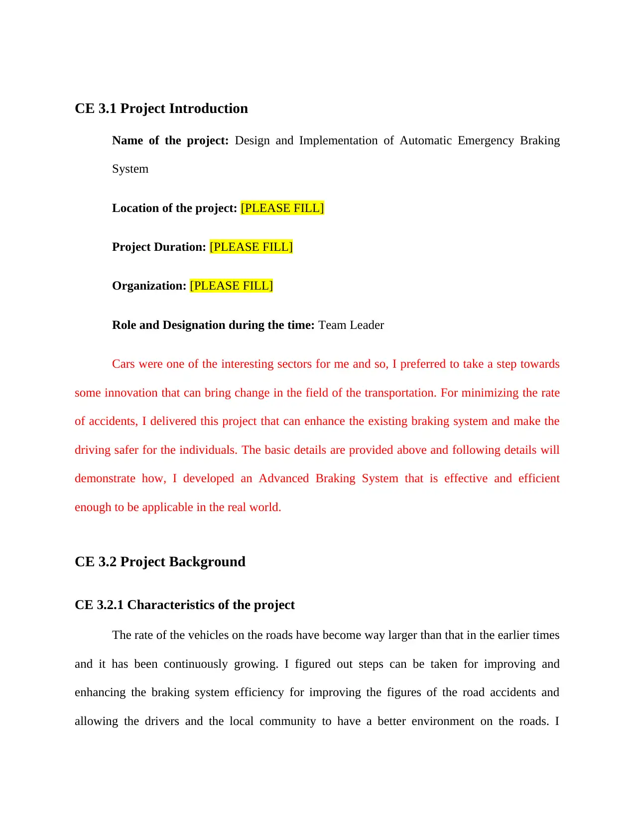
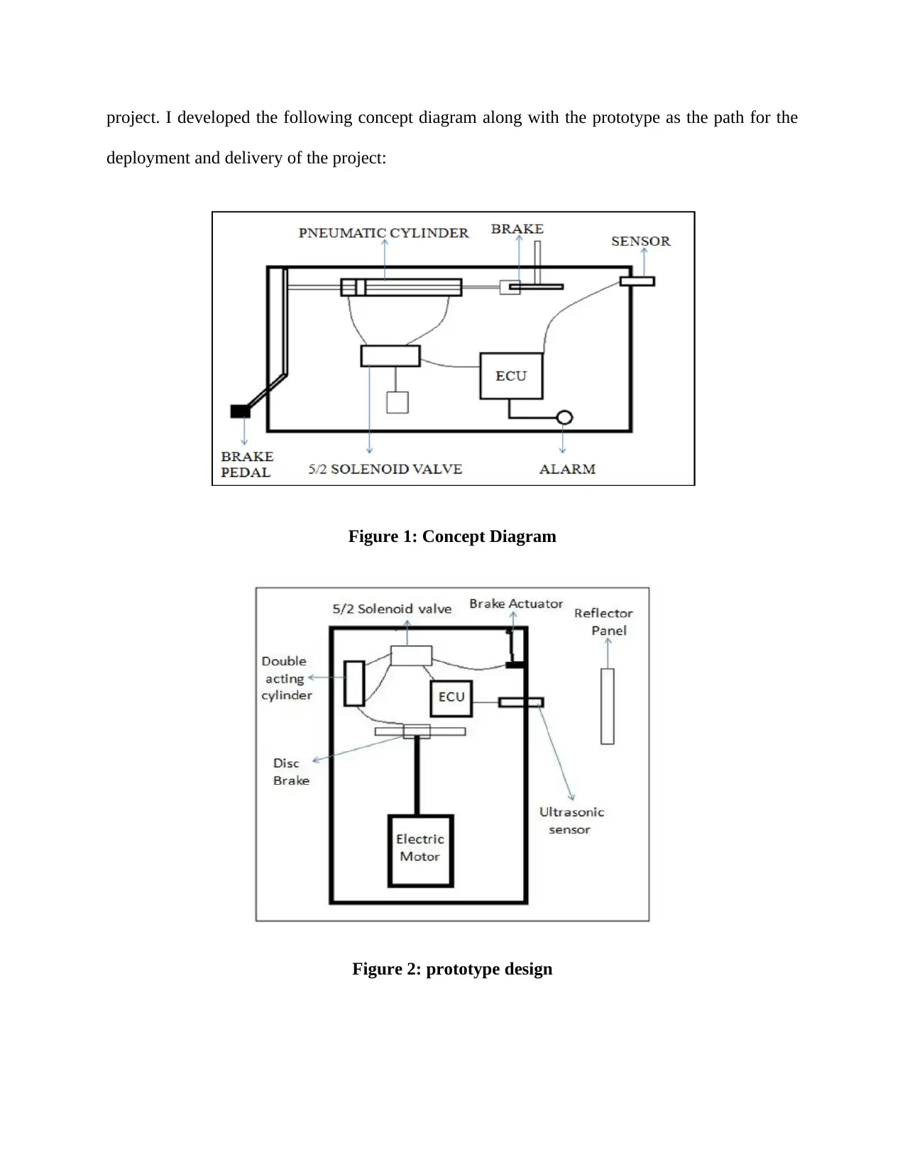
This report details a student's project focused on designing and implementing an Automatic Emergency Braking System (AEBS). The project aimed to enhance vehicle safety by developing a system that automatically applies brakes in emergency situations. The report covers the project's introduction, background, objectives, the student's role as team leader, and responsibilities. It describes the engineering knowledge and skills applied, including the use of sensors, solenoid valves, and PLC circuits. The report also discusses identified issues, solutions, and the collaborative work involved. The project's review summarizes the findings, emphasizing the potential of AEBS to reduce accidents and improve road safety. The report provides insights into the design, implementation, and evaluation of the AEBS, highlighting the student's contributions and the project's outcomes. The system was tested and the report includes the results and analysis of the system's performance and the impact of the technology on vehicle safety.

COMPETENCY
DEMONSTRATION REPORT
Career Episode 3
DEMONSTRATION REPORT
Career Episode 3
Paraphrase This Document
Need a fresh take? Get an instant paraphrase of this document with our AI Paraphraser

CE 3.1 Project Introduction
Name of the project: Design and Implementation of Automatic Emergency Braking
System
Location of the project: [PLEASE FILL]
Project Duration: [PLEASE FILL]
Organization: [PLEASE FILL]
Role and Designation during the time: Team Leader
Cars were one of the interesting sectors for me and so, I preferred to take a step towards
some innovation that can bring change in the field of the transportation. For minimizing the rate
of accidents, I delivered this project that can enhance the existing braking system and make the
driving safer for the individuals. The basic details are provided above and following details will
demonstrate how, I developed an Advanced Braking System that is effective and efficient
enough to be applicable in the real world.
CE 3.2 Project Background
CE 3.2.1 Characteristics of the project
The rate of the vehicles on the roads have become way larger than that in the earlier times
and it has been continuously growing. I figured out steps can be taken for improving and
enhancing the braking system efficiency for improving the figures of the road accidents and
allowing the drivers and the local community to have a better environment on the roads. I

developed a system Advanced Emergency Braking System (AEBS) that can be efficient and
effective in reducing the casualties and preventions from the accidents. I used photoelectric
distance measuring sensors for calculating the distance, electronic control, single acting
hydraulic cylinder, sensors, and hydraulic circuit. I installed the sensor that can be efficient for
measuring the hurdles till 10m and take better decision-making for the vehicles assuring less
accidents.
CE 3.2.2 Objectives developed for the project
I was guiding the team towards the accomplishment of the project deliveries and hence, it
was my duty to develop the feasible set of objectives:
To improve the braking system
To enhance the drivers to react automatically while there is the need of emergency brake
To deliver the project within the expected constraints and manage them throughout the
project
To make sure that every team member contributes in the project effectively and
efficiently
To develop an automated system that can react during the instances when manual brakes
are not applied by the driver and prevent further casualties
CE 3.2.3 My area of work
I was assigned as the guide or team leader and hence, my primary duty was to develop
the effective and efficient project plan that can meet the necessary objectives and goals. I
managed and assigned the different roles and objectives to every team member involved in the
⊘ This is a preview!⊘
Do you want full access?
Subscribe today to unlock all pages.

Trusted by 1+ million students worldwide

project. I developed the following concept diagram along with the prototype as the path for the
deployment and delivery of the project:
Figure 1: Concept Diagram
Figure 2: prototype design
deployment and delivery of the project:
Figure 1: Concept Diagram
Figure 2: prototype design
Paraphrase This Document
Need a fresh take? Get an instant paraphrase of this document with our AI Paraphraser

I appointed myself to the component selection and the mechanical jobs such as solenoid
valve installation, pneumatic cylinder establishment, and the evaluation of the developed AEBS
on a real car. The project was consisting of two sectors, firstly mechanical establishment and
secondly, pneumatic cylinder. Ultrasonic sensor was used for determining the distance between
the car and the obstacle and reacting the braking responses accordingly.
CE 3.2.4 Project Group
CE 3.2.5 My responsibilities throughout the project
I was responsible for the delivery of the entire project and the final output of the project. I
had to make sure that both the phases of the project including mechanical and electrical is being
delivered in an effective and efficient manner and all the expected outcomes are being managed
in an efficient and effective manner. I was also responsible for evaluating the developed project

in the real-world application and make sure that the project is feasible and efficient enough for
the management and delivery of the expected outcomes that was to restrict the number of
accidents. I had the responsibility of the DC motor linear actuator management for the delivery
of the project and hence following specifications were kept constant throughout the project
delivery:
Specifications:
Stroke length: 2 inch
Voltage: 12V DC
Duty cycle: 25%
No load current < 1 Amp
Max load current: 3 Amp
STEP DOWN LOW FREQUENCY TRANSFORMER
Specifications:
Coil structure: Toroidal
Power: 0.5 V-amp to 200 V-amp
Phase: Single phase
Cooling: Air cooled
Winding turns: Autotransformer or Encapsulated Transformer
⊘ This is a preview!⊘
Do you want full access?
Subscribe today to unlock all pages.

Trusted by 1+ million students worldwide

CE 3.3 Distinctive Activity
CE 3.3.1 Comprehending the theory of the project
The development in recent years can be seen in the advancement and increased number
of the vehicle technology comparing the relations between the sensing systems and the braking
systems. There have been many researches and development led by the researchers for
preventing the target mitigation and the accidents such as ASS (active safety systems), AEBS
(Advanced Emergency Braking Systems) and many more. AEBS (Advanced Emergency
Braking Systems) is being reported as the most appropriate and effective technology that can be
helpful in limiting the casualties and preventing the accidents. I developed the project that aims
to distinguishing between the systems those have been currently in production such as electronic
brake force distribution (EBD), brake assist (BA), electronic stability control (ESC), and traction
control (TC) functions and similar systems those are still in the development phase. I developed
the prototype of the system that can be helpful in offering the collision functionality in the
production vehicle that can be operated automatically with the help of the high profile based
relay circuit and applying modifications in traditional braking system that can be efficient and
effective in developing the traditional braking system. It will be much efficient than the previous
approaches in preventing the accidents and restoring the safety on the roads.
CE 3.3.2 Engineering knowledge and skills applied in the project
I used the following components for the delivery and management of the entire project:
a) 5/2 solenoid valve: I used it for bypassing the braking circuit in manner to actuate
the brakes.
Paraphrase This Document
Need a fresh take? Get an instant paraphrase of this document with our AI Paraphraser

b) Braking kit of motorcycle: I used the braking kit of the disk brakes driven by the
brake calipers and motor of the motorcycle in manner to limit the budget of the
project and prototype being developed. I performed the load distribution analysis
as following:
Load distribution is as follows:
60% of total load on rear 2 wheels
40% of total load on front 2 wheels
Load on each wheel:
On Rear wheel: 450 Kg
On front wheel: 300 Kg
c) Ultrasonic sensor: the expected constraint of detecting the obstacles within a
range of 10m.
d) PLC Circuit: I used these ladder logic relays in manner to actuate the solenoid
valve and the alarm system.
e) Reflector based on which, I performed the braking force and pressure analysis:
Static load on wheel Fs = μf× Rn
= 0.6 × 300 × 9.81 Fs
= 1765.8
Dynamic weight transfer Fd = (m × a × h) w

= (450×0.5×9.81×0.508) 2×2 {For a = 0.5 g}
= 280.32 N Total load FT
= Fs + Fd
f) Alarm or hooter
The solenoid valve and pneumatic cylinder were my job sectors and hence, I used valve
to control the flow direction also known as solenoid valve or cut off valve. Since the solenoid
valve is consist of spring, plunger, and electromagnetic coil, the air will be allowed to enter the
pneumatic solenoid valve for the instance when the push button is turn ON. I installed a plunger
that was helpful in connecting the actuator control element to the closure device. I used 5/2
solenoid valve for the double acting cylinder and 3/2 solenoid valve for the single acting
cylinder. I calculated the results during evaluation phase and proposed that more than fifty
percent of the drivers are agree on installing this technology in their cars and felt safer while
driving. However, 30% does not felt any difference and rest of the 10% and 10% felt confident
and nervous respectively while driving the cars with the installed system.
CE 3.3.3 Identified issues and their solutions
3.3.3.1 Issues
I identified that the spring acting on the control element on the valve seat was forcing the
closure device down into the closed position. The second concerning area was the outlet for the
compressed air and the pressure that was supposed to be routing the compressed air. I also
identified that the project was not going as it was meant to be and so, the control and monitoring
⊘ This is a preview!⊘
Do you want full access?
Subscribe today to unlock all pages.

Trusted by 1+ million students worldwide

program was needed to be established. I also analysed that there will be only one outlet for the
instance when the solenoid valve is 3/2.
3.3.3.2 Solutions
I used the solenoid valves in a manner that it can be fitted for the extremely viscous or
contaminated process fluid through supplying the signal to solenoid valve using the application
of ECU. I used 5/2 outlet from solenoid valve that was directly associated to the pneumatic
cylinder along with the help of hose and was helpful in routing the compressed air.
CE 3.3.4 Plan to produce creative and innovative work
I would have kept the project completely mechanically functioning and that could not be
much more automated as the sensors were essential for the automated factors of braking system.
CE 3.3.5 Collaborative work
The team was comprised for five members and I was appointed as one of the team
member and I had to deliver the necessary deliveries within the team. Every member of the team
was responsible of different sections of the project as there were other sectors too other than
designing of the developed automatic braking system. Evaluation. Arrangement, fixing, and
various other activities were accomplished by the team members and I was assigned to these two
sectors and every team member was responsible for delivering their sector of jobs.
CE 3.4 Project Review
CE 3.4.1 Project Summary
I identified that reducing the driving interference of the braking and transferring the
responsibility on the intelligence sensor for the ultimate decision-making can be far more
Paraphrase This Document
Need a fresh take? Get an instant paraphrase of this document with our AI Paraphraser

efficient for the driving system. The automation can be initiated through allowing the automatic
braking system to be activate whenever there is obstacle approaching the distance and thus,
could possibly restrict and limit the number of accidents occurring at the roads.
I also implemented an alarm system that can be effective and efficient in contributing the
elimination of the distractive driving. The simulation results driven after installing the system
demonstrates that through the utilization of the energy absorbing seating system, crash
deceleration can be effectively attenuate occupant injuries and significantly reduce the number
and severity of the damages being caused due to braking accidents.
I gathered experience of various mathematical expressions and the mechanical
engineering works those could be utilized for delivering the project successfully.
1 out of 11
Related Documents

Your All-in-One AI-Powered Toolkit for Academic Success.
+13062052269
info@desklib.com
Available 24*7 on WhatsApp / Email
Unlock your academic potential
Copyright © 2020–2025 A2Z Services. All Rights Reserved. Developed and managed by ZUCOL.