Mechanical Engineering Project: Automatic Hammering Machine Report

Verified

Added on  2023/05/30

|11
|1685
|424
Report
AI Summary
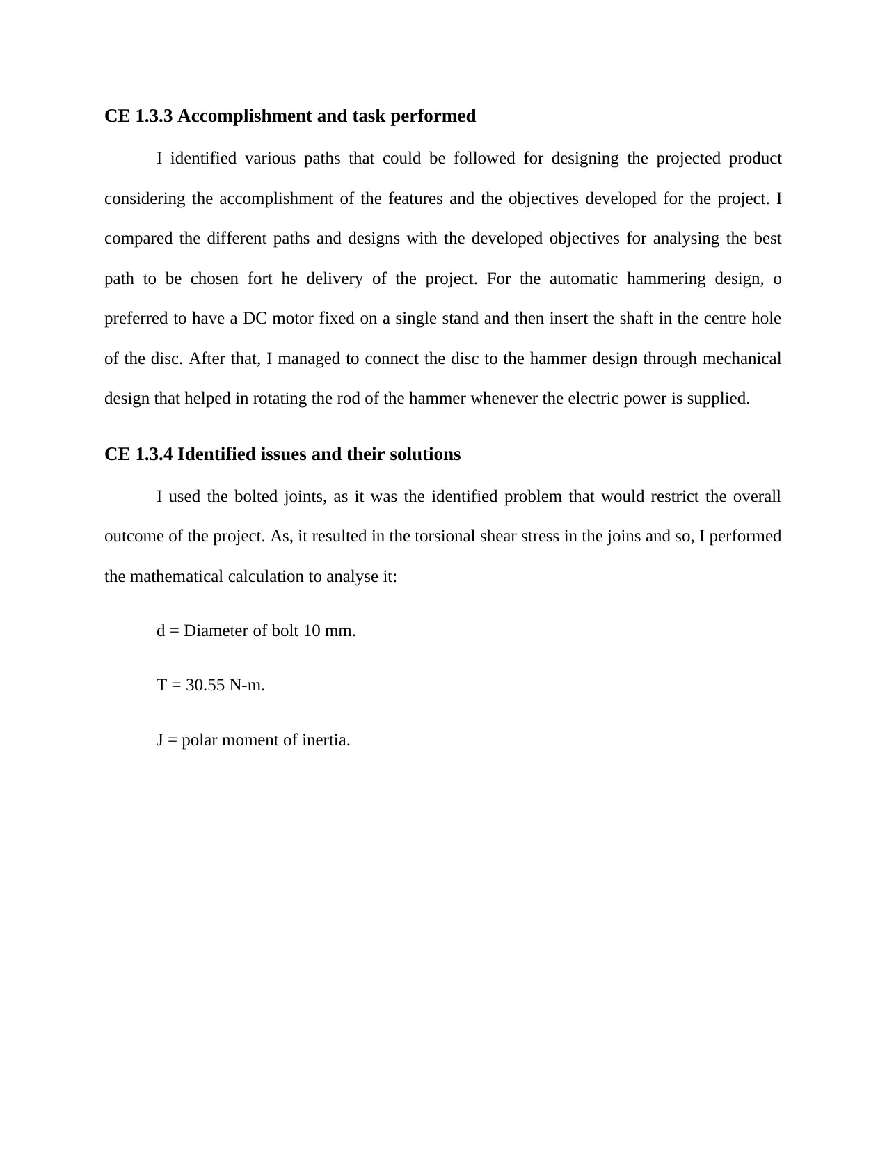
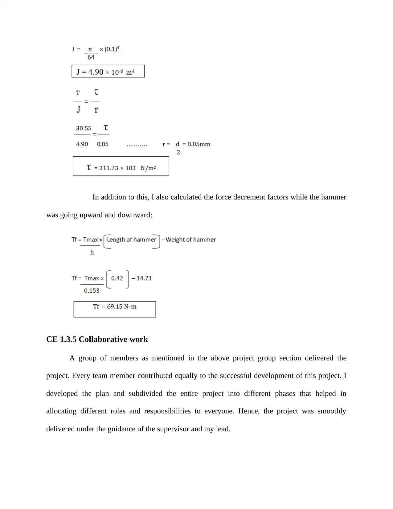
This report details the design, CAD modeling, and fabrication of an automatic hammering machine. The project aimed to automate the hammering process, improving accuracy and efficiency. The report covers the project's background, objectives, and the student's role as a team leader, including strategic planning and technical calculations. It details the application of engineering knowledge, such as the slider-crank mechanism and mathematical calculations for torque and impact velocity. The report also identifies and addresses potential issues, such as torsional shear stress in bolted joints. The project involved the use of CATIA software for modeling and a DC motor for power. The student successfully designed and built an automatic hammering machine, calculating the relevant factors that could impact the machine's performance and ensuring the project met its objectives within the defined timeline. The report provides insights into the design process, calculations, and collaborative work involved in the project.
Document Page
COMPETENCY
DEMONSTRATION REPORT
Career Episode 1
tabler-icon-diamond-filled.svg

Paraphrase This Document

Need a fresh take? Get an instant paraphrase of this document with our AI Paraphraser
Document Page
CE 1.1 Project Information
Name of the project: Design, Cad Modeling & Fabrication of Automatic Hammering
Machine
Location of the project: [PLEASE FILL]
Project Duration: [PLEASE FILL]
Organization: [PLEASE FILL]
Role and Designation during the time: Team Leader
CE 1.2 Project Background
CE 1.2.1 Characteristics of the project
Modern industries are looking for the adoption of the technologies that are capable of
meeting the extended needs and requirements of the consumers. Hammering can be stated as the
backbone of the production industries in which it is being used for the mass production through
efficiently completing bulk operations. I considered this section as one of the opportunities to
explore my knowledge and implement my knowledge for introducing a revolutionary product. I
used CATIA (Computer-aided three-dimensional interactive application) v5R20 software for
producing the solid model of the project assembly. I used the components such as motor, shaft,
hammer, jigs, and fixtures for the successful development of the automatic hammering machine.
I tried to implement the automation in the hammering machine that can be helpful in achieving
the real time hammering with much higher accuracy and precision. The proposed system will
eliminate the load bear by the individual during the hammering process and allow the
Document Page
investigators in the effective and efficient delivery of the necessary operations related to the
hammering. I tried to keep the project budget low as much possible and make sure that the
proposed project is effective and efficient in the end.
CE 1.2.2 Objectives developed for the project
We could not have run into the project blindly, and so, I was asked to lead the team, and
hence, it was one of my responsibility to develop a plan that can be followed for the successful
delivery of the project. I considered the various sectors of the project including technical and
managerial aspects and produced the following set of objectives:
To determine the torque force and impact velocity of the hammer.
To analyse the accomplishment time required for delivering certain activities
To develop the model of the project on CATIA V5R20
To deploy the automation in the hammering process with minimum workforce
To estimate the overall cost and keep it low without hampering the overall quality
of the project
To deliver the project within the defined timeline and make sure that the project
will be provided without any delay
CE 1.2.3 My area of work
My first job was to take the team towards the targeted goals and objectives of the project,
and so, I developed the strategic set of goals that can aim both the technical and management
Document Page
aspects. I listed the features those needed to be considered while designing the entire model those
could be listed as:
1. Fast Hammering Process
2. Instant Hammering
3. No Manual Effort
4. Low Initial Cost
5. Portable System
6. Low Tooling Cost
7. User Friendly
8. Accurate Repetition and Impact
9. Easy Maintenance
I also analysed some of the existing models for considering the best factors that could be
related to the present research. Moreover, I was also assigned for the mathematical
calculation of the various elements and components those we were using for the delivery of
the project.
tabler-icon-diamond-filled.svg

Paraphrase This Document

Need a fresh take? Get an instant paraphrase of this document with our AI Paraphraser
Document Page
CE 1.2.4 Project Group
CE 1.2.5 My responsibilities throughout the project
I was responsible for the identification of the features of the proposed project that needed
to be considered throughout the project lifecycle in the manner to make sure that the product
being developed is capable of meeting the needs and requirements of the end users. I did the
mathematical calculation for calculating the maximum torque produced by the motor. I also
estimated the value of the torque force transmitted in both the upward and downward cases. For
the sophisticated model, impact velocity of the hammer and shear stress also needed to be
calculated and hence, I calculated both the values. The CAD modelling was also considered for
the delivery and management of the project, and so, I used it for developing the various phases of
the modelling for the automated hammer.
Document Page
CE 1.3 Distinctive Activity
CE 1.3.1 Comprehending the theory of the project
The basic principle behind the functioning and operating of the project was mainly about
the assembly machine and upset outline process of programmed compact hammering machine. I
explored this idea to be suitable and replaceable at any place in the industry where labourers are
being appointed for the hammering through adjusting the speed and torque of the hammer. I
applied the slider-crank mechanism for the development of this project that helped in converting
the rotary motion into linear motion. A crank can be described as the arm that has been attached
to the rotating shaft at the 90-degree angle in a manner to reciprocate the action that is being
imparted to or received from the motion.
CE 1.3.2 Engineering knowledge and skills applied in the project
I applied my theoretical and workshop knowledge in efficiently delivering the slider-
crank mechanism that was the crucial part of the entire project. I bent the shaft of the arm in the
place of attaching an external arm at the angle. After that, I connected the end of the connecting
rod to the crank moves in a circular motion that helped in rotating it while keeping the other end
in linear motion. I made the research on the existing designs and selected the proper sizing and
weight of the various components those were about to be used in the project. It includes the
following details:
i. Hammer weight = 1.5 kg.
ii. Total weight =6 kg.
iii. Hammer length =460mm.
iv. Width = 355 mm.
v. Hammer stroke height = 186 mm.
Document Page
vi. Height = 450 mm.
vii. Disc thickness = 1 mm.
viii. Length = 580 mm.
ix. Battery (supply voltage) =12v and 7 Ampere.
x. The diameter of pulley =250 mm.
xi. Typical operation = Common Riveting for 2 mm rivet.
xii. Motor = DENSO INDIA LTD (SR05950-4772), 30 RPM, 12V. DC motor.
xiii. Length of link rod = 200mm.
I performed the mathematical calculations as mentioned above and following formulas
were used:
Motor rating
I = 8 A
N = 30 RPM
V = 12v
Power Transmitted by Motor,
P = VI = 12 × 8 W
P = 96 Watts
Then,
P = 2 πNT/60
96 = 2π30×T/60
T = 30.55 N-m
Distance of rod BA
Applying Pythagoras theorem
(AB) 2 + (153*153)2 = (420*420)
tabler-icon-diamond-filled.svg

Paraphrase This Document

Need a fresh take? Get an instant paraphrase of this document with our AI Paraphraser
Document Page
(AB) = 391.14 mm
CASE 1: When Hammer Moves Downward.
(BC) = h = 153 mm = 0.153 mm
Hammer rod length = 420 mm
= 0.42 m
Maximum torque = 30.55 N-m
= 30.55 × 10³ N-mm
Torque = Tmax/h × Hammer rod length
Tf (Torque Force) = 30.55 × 0.42/0.153
Tf (Torque Force) = 83.86 N-m.
FIND IMPACT VELOCITY OF HAMMER,
H =153 mm = 0.153 m
T (for one re revolution) = 2 sec.
Therefore,
V = h × T = 0.15 × 2
= 0.306 m /sec
Document Page
CE 1.3.3 Accomplishment and task performed
I identified various paths that could be followed for designing the projected product
considering the accomplishment of the features and the objectives developed for the project. I
compared the different paths and designs with the developed objectives for analysing the best
path to be chosen fort he delivery of the project. For the automatic hammering design, o
preferred to have a DC motor fixed on a single stand and then insert the shaft in the centre hole
of the disc. After that, I managed to connect the disc to the hammer design through mechanical
design that helped in rotating the rod of the hammer whenever the electric power is supplied.
CE 1.3.4 Identified issues and their solutions
I used the bolted joints, as it was the identified problem that would restrict the overall
outcome of the project. As, it resulted in the torsional shear stress in the joins and so, I performed
the mathematical calculation to analyse it:
d = Diameter of bolt 10 mm.
T = 30.55 N-m.
J = polar moment of inertia.
Document Page
In addition to this, I also calculated the force decrement factors while the hammer
was going upward and downward:
CE 1.3.5 Collaborative work
A group of members as mentioned in the above project group section delivered the
project. Every team member contributed equally to the successful development of this project. I
developed the plan and subdivided the entire project into different phases that helped in
allocating different roles and responsibilities to everyone. Hence, the project was smoothly
delivered under the guidance of the supervisor and my lead.
tabler-icon-diamond-filled.svg

Paraphrase This Document

Need a fresh take? Get an instant paraphrase of this document with our AI Paraphraser
Document Page
CE 1.4 Project Review
While supplying the DC to the motor through the application of the adopter, the rotation
of the motor shaft can further be transmitted to the spinning motion to the disc. It can be used for
creating an impact force for the required operations that could be helpful in determining the
product quality. I was successful in delivering the project successfully and calculated the related
factors that could have stopped the automatic hammering machine from reaching its highest
potential. I figured the torque force of the motor and used it for automating the hammer.
chevron_up_icon
1 out of 11
circle_padding
hide_on_mobile
zoom_out_icon
[object Object]