Developing an Automatic Room Temperature Control System Project
VerifiedAdded on 2023/01/19
|26
|4149
|92
Project
AI Summary
This project report details the design, implementation, and analysis of an automatic room temperature control system. The system utilizes a PIC16F877A microcontroller, temperature sensors, and actuators (fan and heater) to maintain a desired room temperature. The report covers the control objectives, background information, and system implementation, including circuit diagrams and a list of required materials. It discusses the performance of the controller, the use of PID control, and the challenges faced during implementation. The system employs a closed-loop control strategy, where the microcontroller compares the actual room temperature with a setpoint and activates the heater or fan accordingly. The project also includes flowcharts, pseudocode, and a discussion of software configuration, providing a comprehensive overview of the system's functionality and operation.
Running head: CONTROL SYSTEM
CONTROL SYSTEM
Name of Student
Institution Affiliation
CONTROL SYSTEM
Name of Student
Institution Affiliation
Paraphrase This Document
Need a fresh take? Get an instant paraphrase of this document with our AI Paraphraser
CONTROL SYSTEM 2
Table of contents
Contents
Table of contents.........................................................................................................................................2
Table of figures...........................................................................................................................................2
List of tables................................................................................................................................................3
Description of the Control Objectives.........................................................................................................3
Background information..............................................................................................................................4
Objective Selection......................................................................................................................................6
Identification of the Control Objective........................................................................................................7
Performance of Controller...........................................................................................................................8
System Implementation.............................................................................................................................11
Abstracting the Problem............................................................................................................................14
Problems Faced.........................................................................................................................................15
Software Configuration.............................................................................................................................15
Conclusion.................................................................................................................................................17
References.................................................................................................................................................18
Appendix...................................................................................................................................................20
Table of figures
Figure 1: Showing the block diagram with the major parts of the system......................................6
Figure 2: Showing System flow chart.............................................................................................7
Figure 3: Showing Circuit diagram of the Automatic Room temperature Control system showing
all components of the system.........................................................................................................10
Figure 4: Showing the settling time and stability of the system with PID controller....................12
Figure 5: Showing the settling time and stability of the system without PID controller...............13
CONTROL SYSTEM 3
Figure 1: Showing the block diagram with the major parts of the system....................................16
Figure 2: Showing System flow chart...........................................................................................17
Figure 3: Showing Circuit diagram of the Automatic Room temperature Control system showing
all components of the system.........................................................................................................18
Figure 4: Showing the settling time and stability of the system with PID controller....................19
Figure 5: Showing the settling time and stability of the system without PID controller...............20
List of tables
Table 1: showing List of materials required during implementation..............................................8
⊘ This is a preview!⊘
Do you want full access?
Subscribe today to unlock all pages.
Trusted by 1+ million students worldwide
CONTROL SYSTEM 4
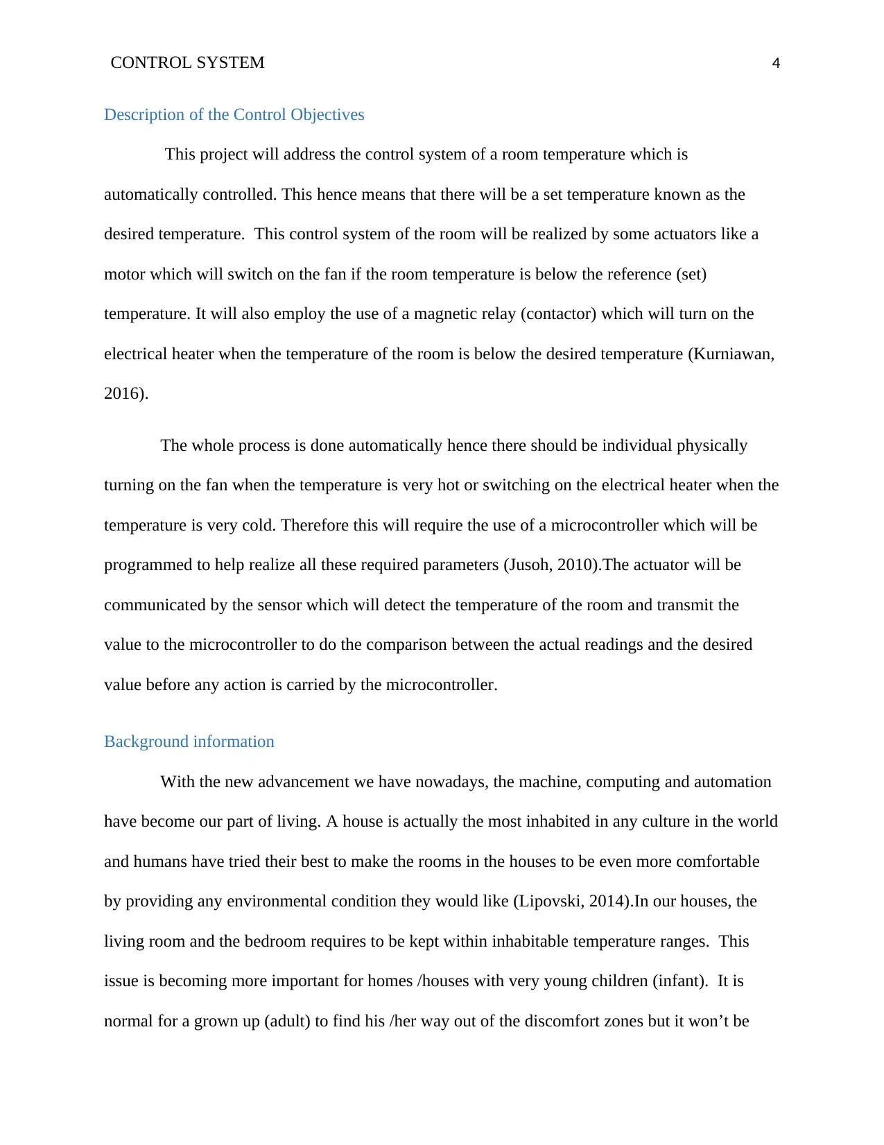
Description of the Control Objectives
This project will address the control system of a room temperature which is
automatically controlled. This hence means that there will be a set temperature known as the
desired temperature. This control system of the room will be realized by some actuators like a
motor which will switch on the fan if the room temperature is below the reference (set)
temperature. It will also employ the use of a magnetic relay (contactor) which will turn on the
electrical heater when the temperature of the room is below the desired temperature (Kurniawan,
2016).
The whole process is done automatically hence there should be individual physically
turning on the fan when the temperature is very hot or switching on the electrical heater when the
temperature is very cold. Therefore this will require the use of a microcontroller which will be
programmed to help realize all these required parameters (Jusoh, 2010).The actuator will be
communicated by the sensor which will detect the temperature of the room and transmit the
value to the microcontroller to do the comparison between the actual readings and the desired
value before any action is carried by the microcontroller.
Background information
With the new advancement we have nowadays, the machine, computing and automation
have become our part of living. A house is actually the most inhabited in any culture in the world
and humans have tried their best to make the rooms in the houses to be even more comfortable
by providing any environmental condition they would like (Lipovski, 2014).In our houses, the
living room and the bedroom requires to be kept within inhabitable temperature ranges. This
issue is becoming more important for homes /houses with very young children (infant). It is
normal for a grown up (adult) to find his /her way out of the discomfort zones but it won’t be
Paraphrase This Document
Need a fresh take? Get an instant paraphrase of this document with our AI Paraphraser
CONTROL SYSTEM 5
possible for the infant or sometimes it won´t be possible during some times like night
(Bhattacharya, 2011).
Again we may need some particular temperature in some places in our houses for
example where perishable goods are kept a very cold temperature is required. This will hence
require the use of the control system in room temperature (Arora, 2010). The idea of the
programmed room temperature control system started back during 18th C and the first person
people believed had this idea was from Norman School in Oklahoma and his name was Warren
Jonson. Before this time Janitors could be sent to go out and find the temperature in every
classroom thereafter Janitors will control the dampers in S basement.
Johnson watched this and then he thought of a good approach to stop all these suffering
Janitors were going through or even limit the problem. Johnson then thought of the automatic
room temperature control system (Leigh, 2012).During the mid-21st C, this control system
resulted in noticeably famous in many homes. Currently, a good measure of work is done and
completed by societies in this sector. A good deal of automatic room temperature control system
products is promptly attainable in the market for example AIRCONS. Weather is something
which keeps o fluctuating and their fluctuations can occur in a very short span of time and this
can lead to external conditions which influence indoor weather condition like temperature.
This paper hence addresses the room temperature control system. Basically, this is like an
air conditioning system that observes the temperature of the room and manages the fresh air
movements in the room without having any person´s involvement. The system will make good
use of the temperature sensors, microcontroller and actuators (fan and heater). The temperature
sensor will take the temperature readings and communicate it with the microcontroller
(UnbehauenHeinz, 2011).
CONTROL SYSTEM 6
Objective Selection
An automatic room temperature control system basically is a self-controlling
temperature where the utilization of the set point is key and it helps in maintaining the room
temperature whether it is hot or cold outside (Passino, 2014).This system will enable the operator
to put the desired temperature, the desired set temperature will be compared against the actual
temperature of the room with the help of sensors for taking the measurement and microcontroller
for comparing the two temperatures. The system will respond by turning ON either the cooler or
the heater depending on the difference after the comparison. This difference done by the
microcontroller is illustrated by the equation below;
Temp diff = Set temp – Actual temp . . . . . . . . . . . . . . . . . . . . . . . . . . . . . . . . . . . . . . . . . . . . 1
When the temperature difference is positive it implies that the set temperature is higher
than the actual temperature hence it is colder outside and for this situation, the microcontroller
will turn on the heater to heat up the room. But in cases where the temperature difference is
negative, it means that the actual temperature is higher hence the environmental temperature is
higher, therefore, the microcontroller will turn on the cooler (fan) to help bring back the
temperature to the desired set value (Bequette, 2012).This will make the system to automatically
control the temperature of the room and tries to make it constant at the required value but it will
be very difficult for this to happen.
This is difficult because of the heating will go higher when the heater tries to reset the
temperature to the desired value. When the sensor detects the same temperature between the
desired temperature and room temperature, it will communicate this to the microcontroller which
will stop the heater (Berenguel, 2014).The heater will be switched off yes but it will still be
giving some higher temperature before it cools and during that time the heater releases some
⊘ This is a preview!⊘
Do you want full access?
Subscribe today to unlock all pages.
Trusted by 1+ million students worldwide
CONTROL SYSTEM 7
unnecessary temperature into the room. And the same will be true during the cooling system, the
cooler (fan) will cool the room temperature until it passes the desired temperature just like in the
cases of the heater.
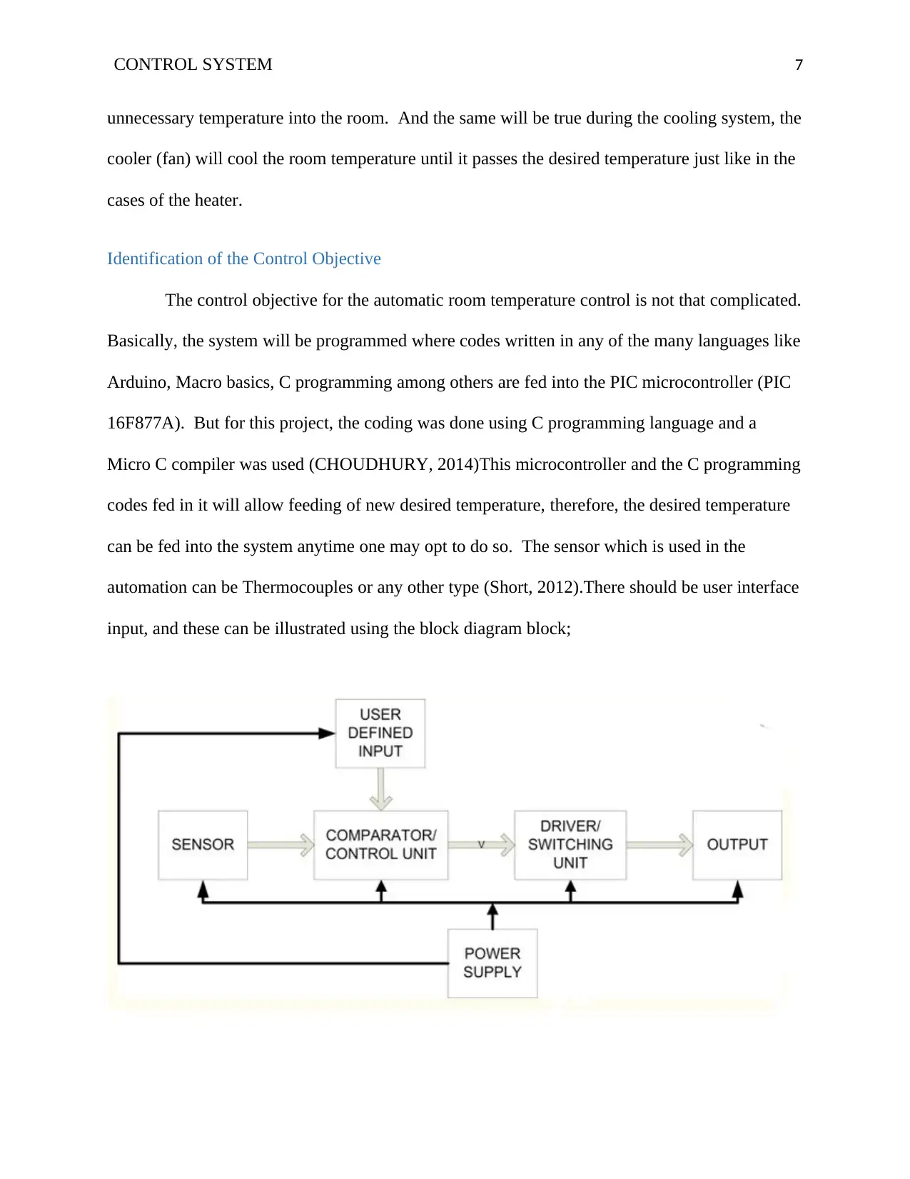
Identification of the Control Objective
The control objective for the automatic room temperature control is not that complicated.
Basically, the system will be programmed where codes written in any of the many languages like
Arduino, Macro basics, C programming among others are fed into the PIC microcontroller (PIC
16F877A). But for this project, the coding was done using C programming language and a
Micro C compiler was used (CHOUDHURY, 2014)This microcontroller and the C programming
codes fed in it will allow feeding of new desired temperature, therefore, the desired temperature
can be fed into the system anytime one may opt to do so. The sensor which is used in the
automation can be Thermocouples or any other type (Short, 2012).There should be user interface
input, and these can be illustrated using the block diagram block;
unnecessary temperature into the room. And the same will be true during the cooling system, the
cooler (fan) will cool the room temperature until it passes the desired temperature just like in the
cases of the heater.
Identification of the Control Objective
The control objective for the automatic room temperature control is not that complicated.
Basically, the system will be programmed where codes written in any of the many languages like
Arduino, Macro basics, C programming among others are fed into the PIC microcontroller (PIC
16F877A). But for this project, the coding was done using C programming language and a
Micro C compiler was used (CHOUDHURY, 2014)This microcontroller and the C programming
codes fed in it will allow feeding of new desired temperature, therefore, the desired temperature
can be fed into the system anytime one may opt to do so. The sensor which is used in the
automation can be Thermocouples or any other type (Short, 2012).There should be user interface
input, and these can be illustrated using the block diagram block;
Paraphrase This Document
Need a fresh take? Get an instant paraphrase of this document with our AI Paraphraser
CONTROL SYSTEM 8
Figure 1: Showing the block diagram with the major parts of the system (Bequette, 2012).
Performance of Controller
The control unit in a room will be PIC 16F877A microcontroller, this microcontroller is
employed because it has a very much reduced instruction set in computer design (Letherman,
2014).For this reason, this PIC makes the codes highly efficient making PIC to operate with a
basically slight memory of the program as compared to other types of microcontrollers like 8081
based microcontroller. This microcontroller has a relatively low cost of installation but has
addition high clocking speed of the microcontroller. Other devices in this microcontroller are two
relays to help in switching ON and OFF of the heater and fan depending on the temperature
variation
Primarily the operator is prompted to set the temperature at the input which he or she
desires to be maintained in the room. The thermocouple which is the temperature sensor will
measure the room temperature (actual temperature) and communicate with the PIC to help
compare the actual temperature and the desired temperature of the room. The microcontroller
will read the temperature send to it after every 10 s and compare it with the set value (desired
temperature value) for every 10 seconds. In case the actual temperature is fewer than the set
value, then the heater will be turned ON automatically to help heat up the room and this will be
done up to that point the temperature returns back to the desired temperature and turn the heater
OFF.
When the actual temperature is higher than the set temperature value then the
microcontroller will turn ON a fan/cooler to help cool the room until the room temperature
CONTROL SYSTEM 9
returns to reference point. When the temperature reaches that value (reference point) it will turn
OFF the fan/cooler. The temperature measured from the room is in analogue form, therefore, the
microcontroller will have to contain an inbuilt analogue to digital converter that will be
employed to convert the analogue signal to digital signal. This conversion is very important
because this microcontroller is a digital gadget and can only understand the analogue signals that
are to say it will only use the binary numbers. Figure 2 below illustrates the flow chart of the
process of the automatic room temperature control system. And the Pseudocodes for the
operation of this microcontroller is given below.
⊘ This is a preview!⊘
Do you want full access?
Subscribe today to unlock all pages.
Trusted by 1+ million students worldwide
CONTROL SYSTEM
10
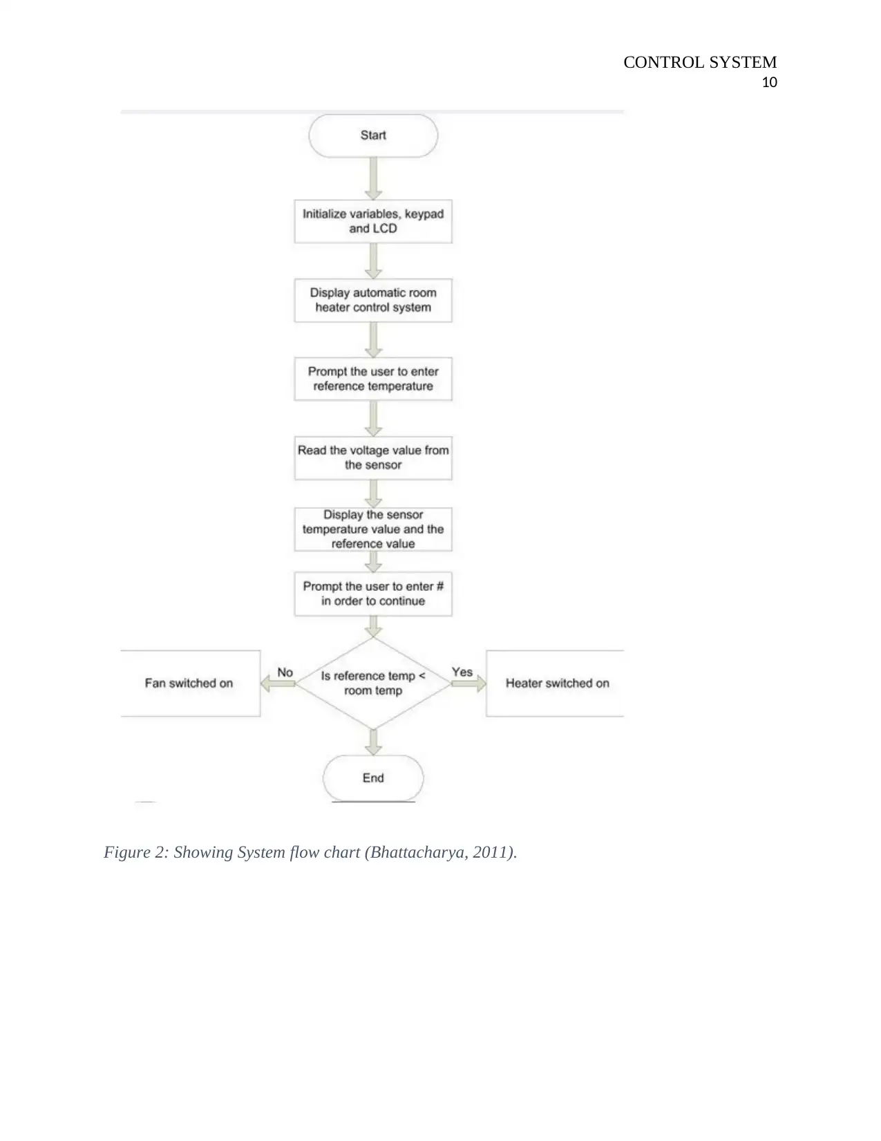
Figure 2: Showing System flow chart (Bhattacharya, 2011).
10
Figure 2: Showing System flow chart (Bhattacharya, 2011).
Paraphrase This Document
Need a fresh take? Get an instant paraphrase of this document with our AI Paraphraser
CONTROL SYSTEM
11
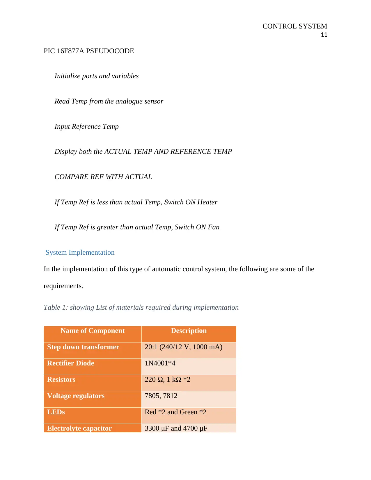
PIC 16F877A PSEUDOCODE
Initialize ports and variables
Read Temp from the analogue sensor
Input Reference Temp
Display both the ACTUAL TEMP AND REFERENCE TEMP
COMPARE REF WITH ACTUAL
If Temp Ref is less than actual Temp, Switch ON Heater
If Temp Ref is greater than actual Temp, Switch ON Fan
System Implementation
In the implementation of this type of automatic control system, the following are some of the
requirements.
Table 1: showing List of materials required during implementation
Name of Component Description
Step down transformer 20:1 (240/12 V, 1000 mA)
Rectifier Diode 1N4001*4
Resistors 220 Ω, 1 kΩ *2
Voltage regulators 7805, 7812
LEDs Red *2 and Green *2
Electrolyte capacitor 3300 μF and 4700 μF
11
PIC 16F877A PSEUDOCODE
Initialize ports and variables
Read Temp from the analogue sensor
Input Reference Temp
Display both the ACTUAL TEMP AND REFERENCE TEMP
COMPARE REF WITH ACTUAL
If Temp Ref is less than actual Temp, Switch ON Heater
If Temp Ref is greater than actual Temp, Switch ON Fan
System Implementation
In the implementation of this type of automatic control system, the following are some of the
requirements.
Table 1: showing List of materials required during implementation
Name of Component Description
Step down transformer 20:1 (240/12 V, 1000 mA)
Rectifier Diode 1N4001*4
Resistors 220 Ω, 1 kΩ *2
Voltage regulators 7805, 7812
LEDs Red *2 and Green *2
Electrolyte capacitor 3300 μF and 4700 μF
CONTROL SYSTEM
12
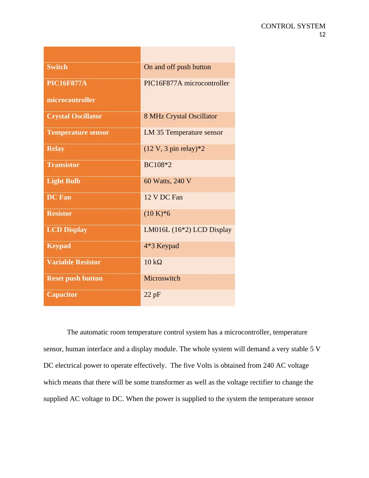
Switch On and off push button
PIC16F877A
microcontroller
PIC16F877A microcontroller
Crystal Oscillator 8 MHz Crystal Oscillator
Temperature sensor LM 35 Temperature sensor
Relay (12 V, 3 pin relay)*2
Transistor BC108*2
Light Bulb 60 Watts, 240 V
DC Fan 12 V DC Fan
Resistor (10 K)*6
LCD Display LM016L (16*2) LCD Display
Keypad 4*3 Keypad
Variable Resistor 10 kΩ
Reset push button Microswitch
Capacitor 22 pF
The automatic room temperature control system has a microcontroller, temperature
sensor, human interface and a display module. The whole system will demand a very stable 5 V
DC electrical power to operate effectively. The five Volts is obtained from 240 AC voltage
which means that there will be some transformer as well as the voltage rectifier to change the
supplied AC voltage to DC. When the power is supplied to the system the temperature sensor
12
Switch On and off push button
PIC16F877A
microcontroller
PIC16F877A microcontroller
Crystal Oscillator 8 MHz Crystal Oscillator
Temperature sensor LM 35 Temperature sensor
Relay (12 V, 3 pin relay)*2
Transistor BC108*2
Light Bulb 60 Watts, 240 V
DC Fan 12 V DC Fan
Resistor (10 K)*6
LCD Display LM016L (16*2) LCD Display
Keypad 4*3 Keypad
Variable Resistor 10 kΩ
Reset push button Microswitch
Capacitor 22 pF
The automatic room temperature control system has a microcontroller, temperature
sensor, human interface and a display module. The whole system will demand a very stable 5 V
DC electrical power to operate effectively. The five Volts is obtained from 240 AC voltage
which means that there will be some transformer as well as the voltage rectifier to change the
supplied AC voltage to DC. When the power is supplied to the system the temperature sensor
⊘ This is a preview!⊘
Do you want full access?
Subscribe today to unlock all pages.
Trusted by 1+ million students worldwide
1 out of 26
Related Documents


Your All-in-One AI-Powered Toolkit for Academic Success.
+13062052269
info@desklib.com
Available 24*7 on WhatsApp / Email
![[object Object]](/_next/static/media/star-bottom.7253800d.svg)
Unlock your academic potential
Copyright © 2020–2026 A2Z Services. All Rights Reserved. Developed and managed by ZUCOL.