Engineering Design: Automatic Street Light Controller with GSM Device
VerifiedAdded on 2023/06/13
|13
|2647
|179
Project
AI Summary
This project addresses the challenge of high electricity bills for street lights by proposing an automatic street light controller circuit integrated with a GSM device. The system utilizes Light Dependent Resistors (LDRs) to detect changes in light intensity and automatically adjust the street lights accordingly, reducing energy consumption. The GSM module enables remote monitoring and control, providing real-time updates to a central control center for efficient maintenance and management. The project details the design, materials, and working principles of the system, including the use of relays, transistors, and other electronic components. The literature review covers LDRs, their working principles, and their application in street lighting, as well as the role of relays as electromagnetic switches. The system aims to reduce electricity consumption and improve the monitoring of street lights, offering a practical solution for city and municipal councils.
Engineering design project 1
ELECTRICAL AND ELECTRONICS ENGINEERING DESIGN PROJECT
By Name
Course
Instructor
Institution
Location
Date
ELECTRICAL AND ELECTRONICS ENGINEERING DESIGN PROJECT
By Name
Course
Instructor
Institution
Location
Date
Paraphrase This Document
Need a fresh take? Get an instant paraphrase of this document with our AI Paraphraser
Engineering design project 2
Abstract
Many city and municipal councils are facing challenges of high electricity bills for the street
lights as the demand for the security light has gone up. Coming up with an automatic street
lights is the only way to solve the challenges of high electricity bills for the councils. Also
there should be a proper monitoring of the street lights. The intensity of light is usually kept
highest when it is very dark and the intensity of light continue to decrease as the amount of
lightness continue decreasing until it shut downs when it is very clear in the morning. The
lights usually turns on and the intensity of the light continue to increase as the amount of
darkness increases.
Engineering design project 3
Table of Contents
1.0 Introduction..........................................................................................................................3
2.0 Aims/objectives of the project.............................................................................................4
3.0 Materials and equipment......................................................................................................4
4.0Literature review...................................................................................................................5
4.1Light depended resistors...............................................................................................5
4.2 Working principle of the Light Depended Resistor.....................................................6
4.3 Circuit Diagram of a Light Dependent Resistor..........................................................7
4.4 Light depended resistors light intensity for street lights..............................................8
4.5 Relay............................................................................................................................8
5.0 Discussions...........................................................................................................................9
6.0 Conclusion..........................................................................................................................10
7.0 References..........................................................................................................................11
⊘ This is a preview!⊘
Do you want full access?
Subscribe today to unlock all pages.
Trusted by 1+ million students worldwide
Engineering design project 4
HOW TO DESIGN AN AUTOMATIC STREET LIGHT CONTROLLER CIRCUIT
WITH GSM DEVICE USING RELAY AND LDR.
1.0 Introduction
Majority of the city and municipal councils around the world are facing challenges of high
electricity bills for the street lights as the demand for the security light has gone up. The
increase in the amount of the electricity bills has been attributed the early switching on and
late switching off of the street lights. Also poor monitoring of the street light has also been
attributed to be increasing the amount of electricity bills which the councils are paying.
Coming up with an automatic street lights is the only way to solve the challenges of high
electricity bills for the councils. Also there should be a proper monitoring of the street lights.
Updated information about the street lights needs to be submitted to the control centre of the
street light so as to ensure that there is proper monitoring of the street lights. Having the
updated information of the street lights in place it gives the maintenance team an easy time to
locate where the problems are in the system once they occur. The best way to achieve
automatic lighting for the streets is by having an automatic lighting system in place which is
able to relay messages when the lights are to go on and when they go off (Bedford, 2014, p.
346).
2.0 Aims/objectives of the project.
The objectives of this project are as stated below.
To find out the difficulties involved in street lighting.
To come up with a solution which will help in reduction of the electricity consumption.
To develop an automatic lighting system for the street light which uses light depended
resistors and the GSM network to relay messages to the control system.
Paraphrase This Document
Need a fresh take? Get an instant paraphrase of this document with our AI Paraphraser

Engineering design project 5
Design a system which is able to monitor the lighting of the streets automatically.
To control the electricity bills which are paid by the city and municipal council through the
reduction of electricity usages.
3.0 Materials and equipment
The materials and equipment which will be required to carry out the project include:
Relay
Transistor BC547 -2
Resistor 1k
100k Potentiometer
LDR (Light Dependent Resistor
Power Supply 12v -1
GSM device
1n4007 Diode
Connecting wires
Perf Board or Bread Board
Jumper wires
Bulb or AC Load
Screw terminal Block 2 pin or 3 pin
AC supply.
Engineering design project 6
4.0 Literature review
4.1Light depended resistors
Light depended resistors which are also referred to as photo resistors, photoconductors or
photocell is a category of resistors whose resistance changes depending on the amount of
light which falls on its surface. When light falls on its surface it resistance varies. These type
of resistance have a lot of applications where it is needed to sense the availability of light.
The light depended resistors have a lot of applications for example the automatic turning on
and off of lights. A typical LDR has a resistance of 1MOhm in darkness and a resistance of a
couple of KOhm in brightness (Bikshalu, 2015, p. 113).
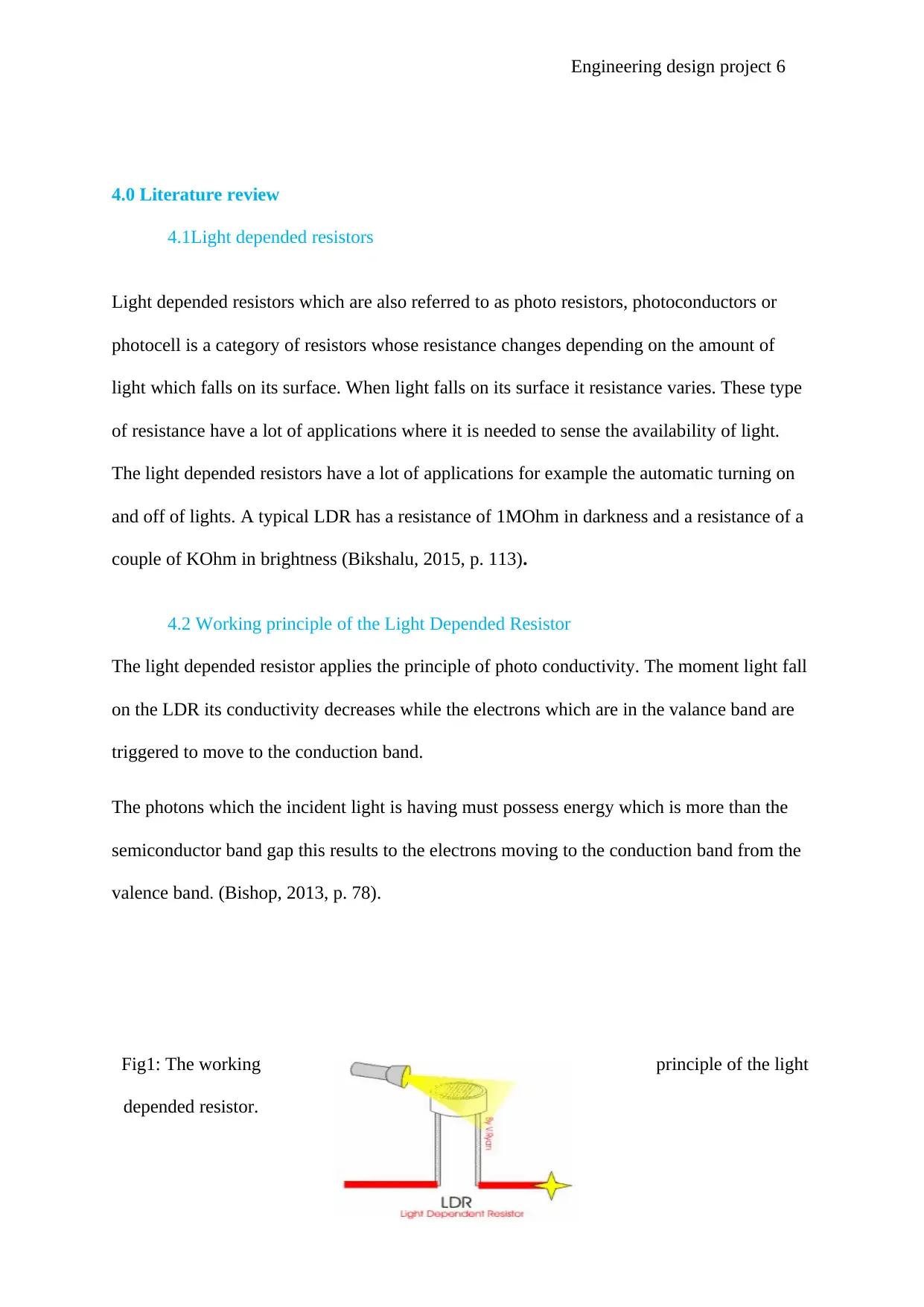
4.2 Working principle of the Light Depended Resistor
The light depended resistor applies the principle of photo conductivity. The moment light fall
on the LDR its conductivity decreases while the electrons which are in the valance band are
triggered to move to the conduction band.
The photons which the incident light is having must possess energy which is more than the
semiconductor band gap this results to the electrons moving to the conduction band from the
valence band. (Bishop, 2013, p. 78).
Fig1: The working principle of the light
depended resistor.
4.0 Literature review
4.1Light depended resistors
Light depended resistors which are also referred to as photo resistors, photoconductors or
photocell is a category of resistors whose resistance changes depending on the amount of
light which falls on its surface. When light falls on its surface it resistance varies. These type
of resistance have a lot of applications where it is needed to sense the availability of light.
The light depended resistors have a lot of applications for example the automatic turning on
and off of lights. A typical LDR has a resistance of 1MOhm in darkness and a resistance of a
couple of KOhm in brightness (Bikshalu, 2015, p. 113).
4.2 Working principle of the Light Depended Resistor
The light depended resistor applies the principle of photo conductivity. The moment light fall
on the LDR its conductivity decreases while the electrons which are in the valance band are
triggered to move to the conduction band.
The photons which the incident light is having must possess energy which is more than the
semiconductor band gap this results to the electrons moving to the conduction band from the
valence band. (Bishop, 2013, p. 78).
Fig1: The working principle of the light
depended resistor.
⊘ This is a preview!⊘
Do you want full access?
Subscribe today to unlock all pages.
Trusted by 1+ million students worldwide
Engineering design project 7
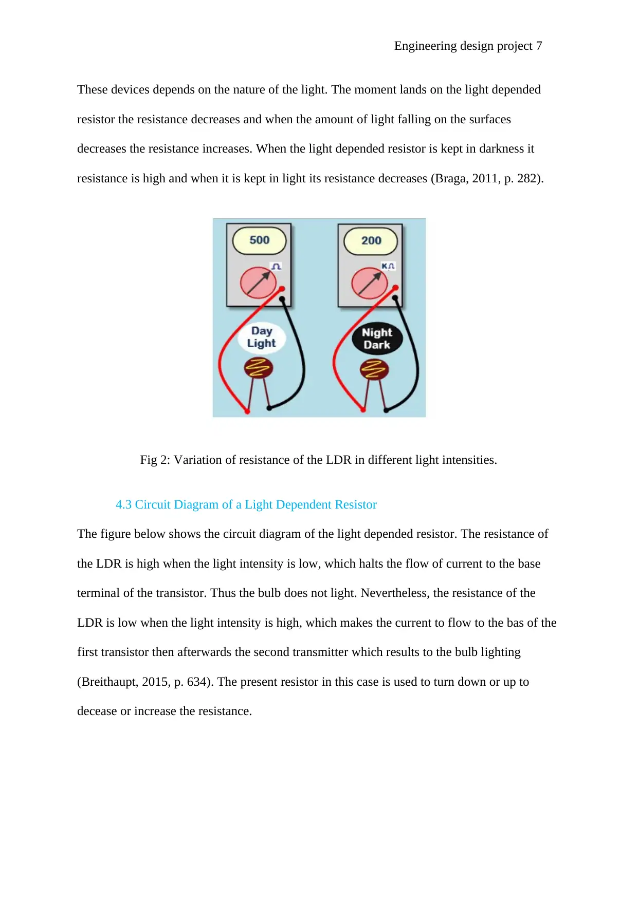
These devices depends on the nature of the light. The moment lands on the light depended
resistor the resistance decreases and when the amount of light falling on the surfaces
decreases the resistance increases. When the light depended resistor is kept in darkness it
resistance is high and when it is kept in light its resistance decreases (Braga, 2011, p. 282).
Fig 2: Variation of resistance of the LDR in different light intensities.
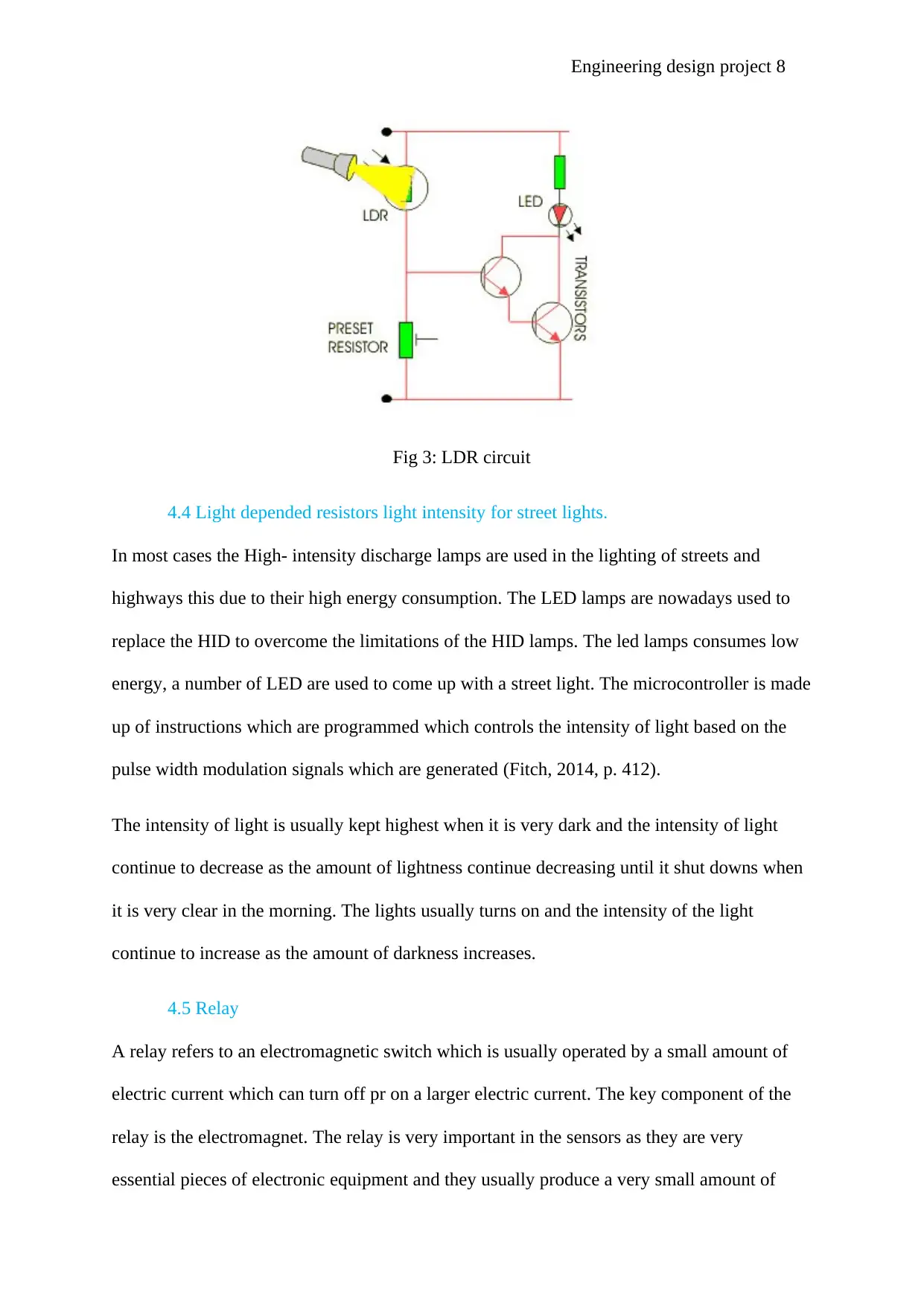
4.3 Circuit Diagram of a Light Dependent Resistor
The figure below shows the circuit diagram of the light depended resistor. The resistance of
the LDR is high when the light intensity is low, which halts the flow of current to the base
terminal of the transistor. Thus the bulb does not light. Nevertheless, the resistance of the
LDR is low when the light intensity is high, which makes the current to flow to the bas of the
first transistor then afterwards the second transmitter which results to the bulb lighting
(Breithaupt, 2015, p. 634). The present resistor in this case is used to turn down or up to
decease or increase the resistance.
These devices depends on the nature of the light. The moment lands on the light depended
resistor the resistance decreases and when the amount of light falling on the surfaces
decreases the resistance increases. When the light depended resistor is kept in darkness it
resistance is high and when it is kept in light its resistance decreases (Braga, 2011, p. 282).
Fig 2: Variation of resistance of the LDR in different light intensities.
4.3 Circuit Diagram of a Light Dependent Resistor
The figure below shows the circuit diagram of the light depended resistor. The resistance of
the LDR is high when the light intensity is low, which halts the flow of current to the base
terminal of the transistor. Thus the bulb does not light. Nevertheless, the resistance of the
LDR is low when the light intensity is high, which makes the current to flow to the bas of the
first transistor then afterwards the second transmitter which results to the bulb lighting
(Breithaupt, 2015, p. 634). The present resistor in this case is used to turn down or up to
decease or increase the resistance.
Paraphrase This Document
Need a fresh take? Get an instant paraphrase of this document with our AI Paraphraser
Engineering design project 8
Fig 3: LDR circuit
4.4 Light depended resistors light intensity for street lights.
In most cases the High- intensity discharge lamps are used in the lighting of streets and
highways this due to their high energy consumption. The LED lamps are nowadays used to
replace the HID to overcome the limitations of the HID lamps. The led lamps consumes low
energy, a number of LED are used to come up with a street light. The microcontroller is made
up of instructions which are programmed which controls the intensity of light based on the
pulse width modulation signals which are generated (Fitch, 2014, p. 412).
The intensity of light is usually kept highest when it is very dark and the intensity of light
continue to decrease as the amount of lightness continue decreasing until it shut downs when
it is very clear in the morning. The lights usually turns on and the intensity of the light
continue to increase as the amount of darkness increases.
4.5 Relay
A relay refers to an electromagnetic switch which is usually operated by a small amount of
electric current which can turn off pr on a larger electric current. The key component of the
relay is the electromagnet. The relay is very important in the sensors as they are very
essential pieces of electronic equipment and they usually produce a very small amount of
Engineering design project 9
electric current but they are used in equipment which uses large current. The relay can work
both as a switch or an amplifier (Karris, 2016, p. 76).
The chemical improved chemical vapour decomposition is a technique of chemical vapour
deposition which applies a plasma to produce some of the energy which is required for
deposition reactions which are to be conducted. This offers a merit of processing of
temperatures which are lower than the application of technique of purely thermal processing
such as the low- pressure chemical vapour deposition. The temperatures between 200oc and
400oc are used for the processing of plasma improved chemical deposition. While the
temperatures of between 425oc and 900oc are applied for the processing of low-pressure
chemical vapour deposition (Zhang, 2012, p. 45).
The plasma improved chemical deposition system which is usually abbreviated as PECVD is
a category of the chemical vapour deposition which is is usually different in the way the
chemical reactions are initiated.
5.0 Discussions
System description.
The system of the automatic lighting is designed in such a way to detect the changes between
light and darkness and with that it can be able to initiate the turn on and turn off of the street
lights. Sensors will be used in this system which will be able to able to sense light and control
the light emitted from the street light according to the intensity of light which is available.
This project will use light depended resistors (LDRs) which are usually semiconductors
materials. The messages regarding to the changes which are made in the system will be
relayed by A GSM which will be connected into the system (Woodside, 2013, p. 543).
⊘ This is a preview!⊘
Do you want full access?
Subscribe today to unlock all pages.
Trusted by 1+ million students worldwide

Engineering design project 10
The main components of the system are the LDRs which are light sensitive. The lighting will
be controlled by the LDRs which will at the same time ensure that the system works
effectively.
The Light depended resistors which are also photo resistors works according to the principle
of photoconductivity, which states that once light falls of the surface of the light depended
resistors, the conductance of the element increases rapidly. This means resistance of the light
depended resistors decreases when struck by a beam of light. The reactions of the light
depended resistors will be according to the amount of light which falls on its surface.
Cadmium sulphide will also be utilised in this project (Sang, 2014, p. 65).
The project will be built on the circuit which is based on the IC CA3140 which is operated by
an amplifier and can at the same time unite the voltage PMOS transistors to the high voltage
bipolar transistor. The main factor in this research project will be to develop the resistance
control of the lighting system and thus determine at which level the lights will go on and off.
The resistance available in the system will determine the amount of current that will flow
through the system. The amount of current which flows through the resistor is equivalent to
the voltage that appears on the resistor.
Capacitors will also be another major components of the system. Usually the capacitors are
made up of the materials which dielectric medium flow of the current between the capacitors
which are available. The relay will also be used in the system to provide the isolation
between the main device and the controller. That is mainly aimed at mo0nitoring the device
regarding to its working condition and at the same time analyse the device to determine
whether it is working on both the DC and AC (Karris, 2016, p. 674).
The relay bridge will be of great significance because it has to receive the signals which are
sent from the microcontroller which the DC works on. Significantly the relay will be applied
Paraphrase This Document
Need a fresh take? Get an instant paraphrase of this document with our AI Paraphraser
Engineering design project 11
when there is need to control an essential amount of voltage or current with small electric
signals. The electric isolation will also be monitored in this project to make sure that the
switching of on and off of the street light happens on the right moments.
6.0 Conclusion
In conclusion, Coming up with an automatic street lights is the only way to solve the
challenges of high electricity bills for the councils. Also there should be a proper monitoring
of the street lights. Updated information about the street lights needs to be submitted to the
control centre of the street light so as to ensure that there is proper monitoring of the street
lights.
The system of the automatic lighting is designed in such a way to detect the changes between
light and darkness and with that it can be able to initiate the turn on and turn off of the street
lights. Sensors will be used in this system which will be able to able to sense light and control
the light emitted from the street light according to the intensity of light which is available.
The intensity of light is usually kept highest when it is very dark and the intensity of light
continue to decrease as the amount of lightness continue decreasing until it shut downs when
it is very clear in the morning. The lights usually turns on and the intensity of the light
continue to increase as the amount of darkness increases.
A relay refers to an electromagnetic switch which is usually operated by a small amount of
electric current which can turn off pr on a larger electric current. The key component of the
relay is the electromagnet. The relay is very important in the sensors as they are very
essential pieces of electronic equipment and they usually produce a very small amount of
electric current but they are used in equipment which uses large current. The relay can work
both as a switch or an amplifier.
Engineering design project 12
7.0 References
Bedford, N., 2014. City Documents: Municipal Register ... Mayor's Address to the Council ...
Annual Reports, Etc. .... 4th ed. London: University of Chicago.
Bikshalu, K., 2015. Basics of Electronics Engineering. 4th ed. Sydney: Educreation
Publishing.
Bishop, O., 2013. Understand Electronics. 4th ed. Chicago: Elsevier.
Braga, N. C., 2011. Robotics, Mechatronics, and Artificial Intelligence: Experimental Circuit
Blocks for Designers. 6th ed. Paris: Elsevier.
Breithaupt, J., 2015. New Understanding Physics for Advanced Level. 3rd ed. Chicago:
Nelson Thornes.
Fitch, A. L., 2014. Development of Memristor Based Circuits. 2nd ed. Chicago: World
Scientific.
Karris, S. T., 2016. Electronic Devices and Amplifier Circuits: With MATLAB Applications.
4th ed. Berlin: Orchard Publications,.
Sang, D., 2014. Cambridge International AS and A Level Physics Coursebook with CD-
ROM. 2nd ed. London: Cambridge University Press.
Woodside, R., 2013. Electronics Projects. 1st ed. Texas: EFY Enterprises Pvt Ltd.
Zhang, W., 2012. Software Engineering and Knowledge Engineering: Theory and Practice:
Selected papers from 2012 International Conference on Software Engineering, Knowledge
Engineering and Information Engineering (SEKEIE 2012). 3rd ed. Texas: Springer Science
& Business Media.
⊘ This is a preview!⊘
Do you want full access?
Subscribe today to unlock all pages.
Trusted by 1+ million students worldwide
1 out of 13
Related Documents


Your All-in-One AI-Powered Toolkit for Academic Success.
+13062052269
info@desklib.com
Available 24*7 on WhatsApp / Email
![[object Object]](/_next/static/media/star-bottom.7253800d.svg)
Unlock your academic potential
Copyright © 2020–2026 A2Z Services. All Rights Reserved. Developed and managed by ZUCOL.