Banking Software Project: Design, Implementation, and Evaluation
VerifiedAdded on 2019/10/18
|27
|5261
|344
Project
AI Summary
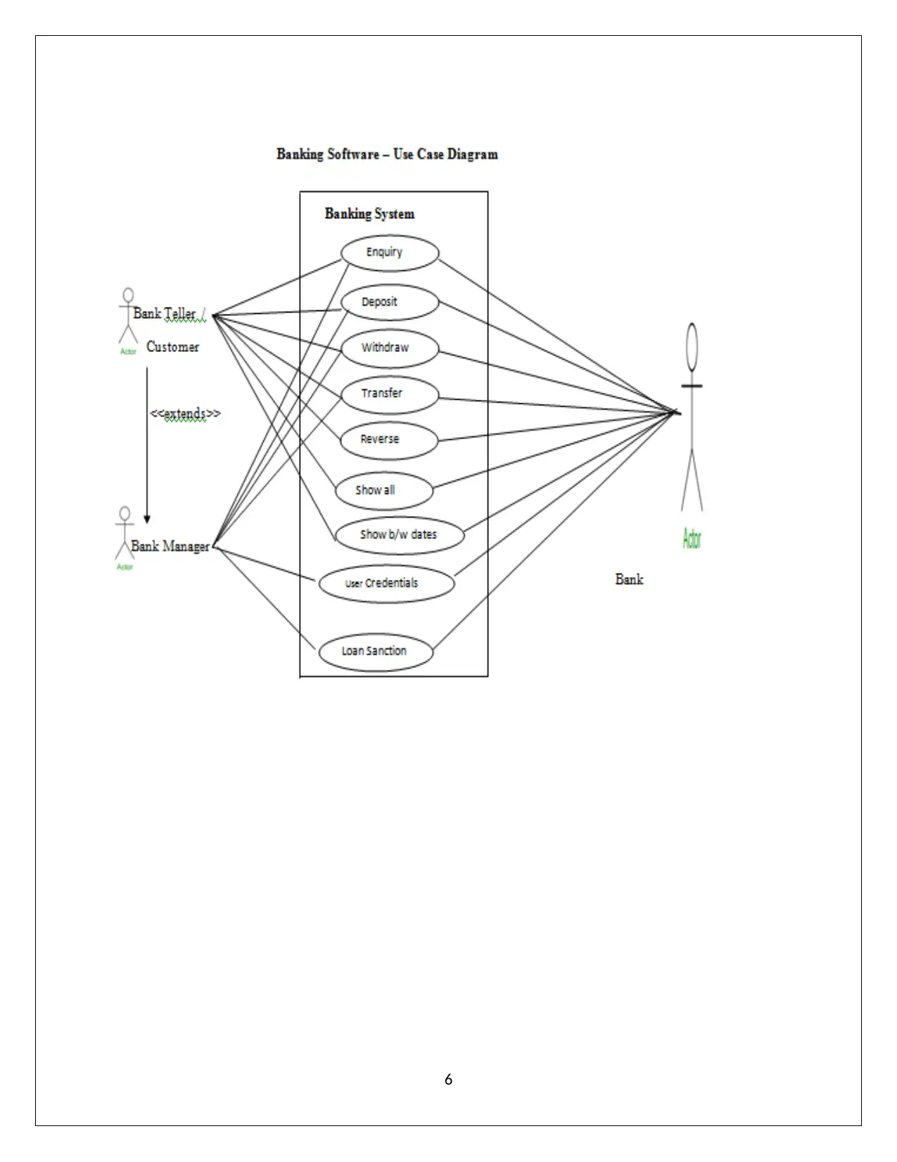
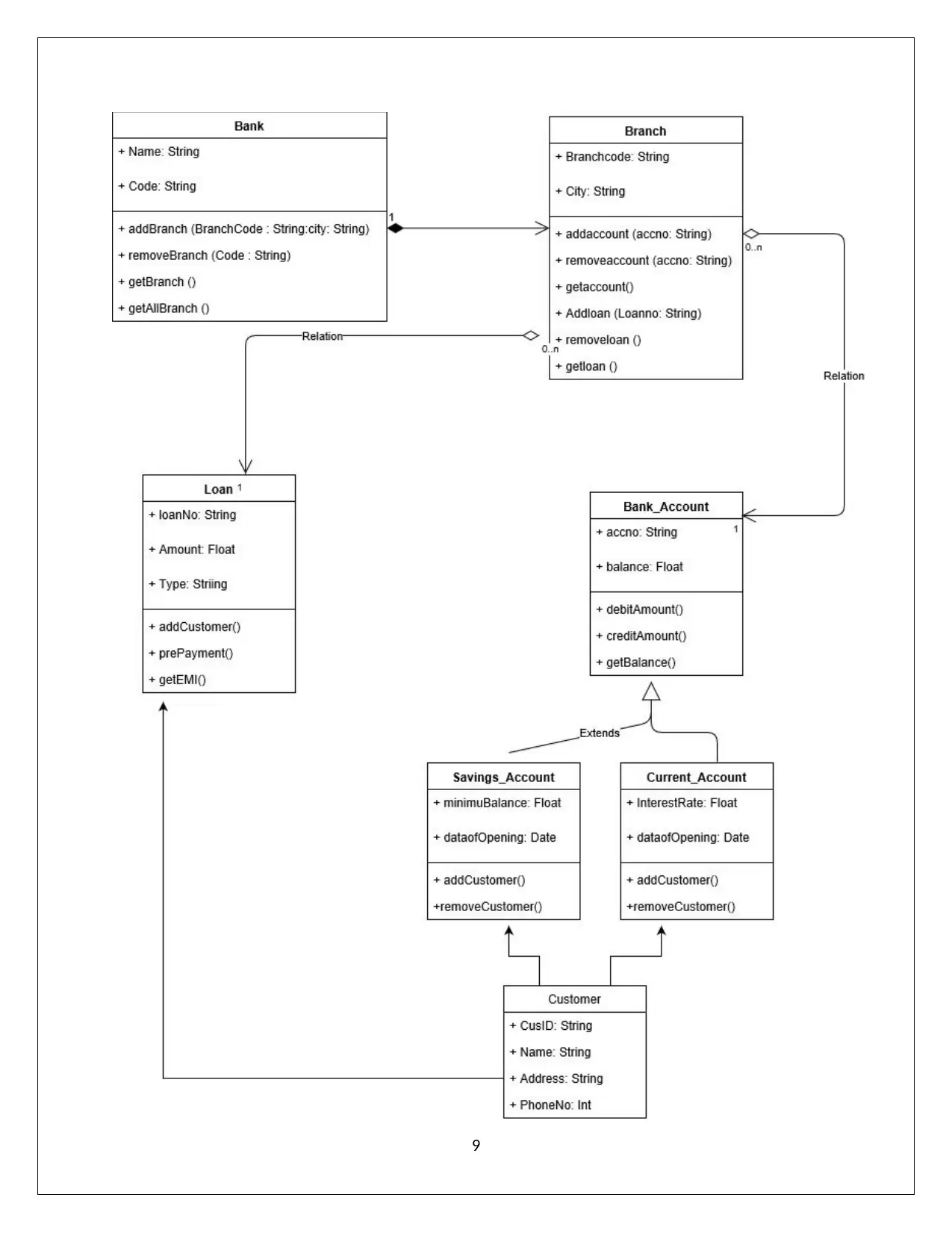
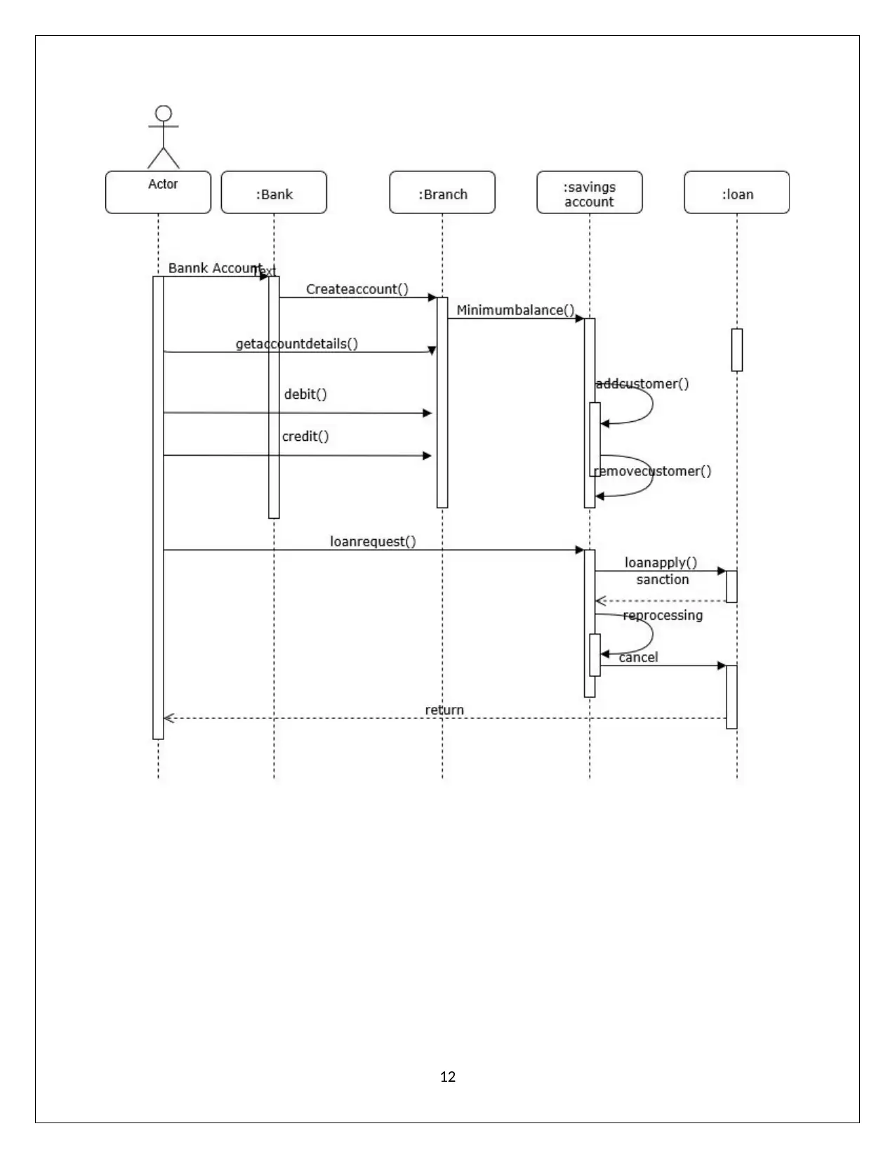
This project details the design and implementation of a banking software system. It begins with a Use Case Model Diagram to illustrate different actors and their actions within the system, followed by a Class Diagram that represents the classes, their attributes, and relationships. A Sequence Diagram is then presented to depict the chronological order of interactions between objects. The project includes the Java code for the software, which incorporates classes for bank accounts, bank tellers, and bank managers, along with exception handling for insufficient funds. The critical discussion section provides a self-reflection on the work, discussing the Software Development Life Cycle (SDLC) phases, including requirement gathering, design, development, software testing, and deployment, as well as addressing any issues encountered and concluding with a summary of the project's achievements.

1
Paraphrase This Document
Need a fresh take? Get an instant paraphrase of this document with our AI Paraphraser

Contents
1.Use Case Model Diagram (Logical Design Diagram)..................................................................4
2.Class Diagram (Logical Design)..................................................................................................6
3.Sequence Diagram (Logical Design)............................................................................................8
4. Program........................................................................................................................................9
Critical Discussion: Introduction...................................................................................................18
NationNarrow Reflection and Critical-Evaluation....................................................................18
Critical self-reflection on the work................................................................................................19
Software Development Life Cycle (SDLC) of this software.....................................................19
Requirement Gathering..........................................................................................................19
Design.....................................................................................................................................19
Development..........................................................................................................................20
Software Testing.....................................................................................................................20
Deployment............................................................................................................................21
Feedback.................................................................................................................................22
Issues..............................................................................................................................................23
Conclusion.....................................................................................................................................23
References......................................................................................................................................24
2

Table of Content
S. NO. CONTENT PAGE NO.
1. Use Case Model Diagram 2
2. Class Diagram 4
3. Sequence Diagram 6
4. Program 8
5. Critical Discussion : Introduction 16
6. Critical self-reflection on the work 17
7. Issues 21
8. Conclusion 21
9. References 22
3
S. NO. CONTENT PAGE NO.
1. Use Case Model Diagram 2
2. Class Diagram 4
3. Sequence Diagram 6
4. Program 8
5. Critical Discussion : Introduction 16
6. Critical self-reflection on the work 17
7. Issues 21
8. Conclusion 21
9. References 22
3
⊘ This is a preview!⊘
Do you want full access?
Subscribe today to unlock all pages.

Trusted by 1+ million students worldwide

1. Use Case Model Diagram (Logical Design Diagram)
This diagram is employed to characterizedifferent actors / users or clients and their
operations or actions or events.This use case diagram is employed to model the structure of
software or a sub system. It highlights the representation of user and their actions in which
the particular user or an actor or a client is working on. It has mainly 2 components one is
actor and two is use case in a specific application.It specifies theusers who are all going to
use particular software without minding the actual implementation of a function. The actors
are the real end users of the software which is depicted using an actor stereotype. The use
case action is specified using oval symbol(Baysal, 2016). It is to be named with an action
verb for functionality. The relationship between actor and a use case symbol is depicted
through a line which linkages the both. In this Banking Software for NatioNarrow Building
Society 3 main use cases where defined. They are
o Bank Manager,
o Bank Teller and Customer.
4
Paraphrase This Document
Need a fresh take? Get an instant paraphrase of this document with our AI Paraphraser

Bank Software - Use Case Diagram Explanation
The following Bank Software Use Case diagram is a diagrammatic representation of
different use cases or actors or users of this particular software. E.g. the bank teller may be one
actor, customer is another actor and bank manager is a one more actor of this software. The bank
teller actor performs actions such as balance enquiry, cash deposit, cash withdrawal and fund
transfer operations in this bank software and he also performs reversing a transaction. Like bank
teller actor, customer actor also performs operations like balance update enquiry, deposit,
withdrawal and transfer operations in this bank software and also request bank statements made
between dates and requesting to show all transactions of an account. The bank manager actor
performing operation includes user credential and loan approval and sanctioning along with
balance enquiry, cash deposit, cash withdrawal and fund transfer operations in this bank
software(Felipe P. Vista IV 1, 2013).
5

6
⊘ This is a preview!⊘
Do you want full access?
Subscribe today to unlock all pages.

Trusted by 1+ million students worldwide

2. Class Diagram (Logical Design)
This diagram is used to represent classes along with its attributes (variables) and methods
(operations) also it is employed to specify relationship among base and derived classes.It is a
logical building of a software program.It provides the complete structure of an object oriented
programming software application. It is an actual depiction of various class usages in software. It
is employed only for object oriented constructs(Nunes, 2018). The group of all the class
depictions forms a class diagram. The class representation box first part should have proper class
name along with the attribute depiction box second part should have the names of a variable and
the method denoting box third part should have the name and return type of the function name.
It is decisively for stagnant depiction of a system. It will be sketched for the languages like c++,
java, php, python, Smalltalk,etc.,
7
Paraphrase This Document
Need a fresh take? Get an instant paraphrase of this document with our AI Paraphraser

Bank- Software - Class Diagram Explanation
In the following Bank software class diagram it is represented with many classes and its
mutual relationship existing among those classes. The class diagram has totally seven classes,
out of seven classes; two classes are built in classes imported from a java packages and the
remaining five classes are user defined classes.The classes are user defined required classes in
the Bank Software. The Bank Account classes are used to perform main bank operations
including debit and credit which is inherited by the class branch. The branch class is added with
the function addAccount() along with the base class bankproperties which is again inherited by
the classbranch which supports functionality like getloan() along with the properties of its base
classbranch.
The user defined classsavings_Account,current_Accountis inherited from the built in
class.The one more user defined class customer is inherited from the built in class r which
support for handling customer information(Pathak, 2017).
8

9
⊘ This is a preview!⊘
Do you want full access?
Subscribe today to unlock all pages.

Trusted by 1+ million students worldwide

Sequence Diagram (Logical Design)
It illustrates dealings among objects in a chronological order.It is also termed as event
diagram or event scenarios. It showcases when oneobject finishes it operations and when another
begins its work. It is for the depiction of factual time state of affairs. It shows the manner how a
system is moving on while it’s functioning. The symbols employed to draw basically the
sequence diagram involves an actor, life lines, messages, etc., The Actor is an external entity
which is employed to play a role on a system functioning.It is placed at the top of the line .Any
number of actors can be involved in a scenario depending upon the system. Each instance of a
class is depicted as a life line which is also placed at the top of a line. It is a name represented
component of a sequence diagram(R S Madanayake1, 2017). The life line is an internal
component of a sequence diagram.
The messages are depicted using an arrow line which shows the contact between objects or
among an instance of a class or an object. Messages and lifeline are the vital components for the
depiction of a sequence diagram. In the below diagram Bank actor is involved along with the life
lines which has an instance of the classes AccountCreationbranch and Loan.
10
Paraphrase This Document
Need a fresh take? Get an instant paraphrase of this document with our AI Paraphraser

Banking Software – Sequential Diagram Explanation
In the following Banking Software- sequential diagram is explored.It is a diagram which
shows the sequential actions flows in the banking software. In the diagram actor bank and
instances of classes are involved.
The actor is Bank which is involved along with the life lines which is actually an instance of
the classes existing in the Bank software which includes AccountCreation,branch and Loan.
Initially instance of BankAccount is activated toward the Account creation then it is
communicated towards the branchInstance followed by show details debitcredit messages are
communicated to the instance of a class branch. During debit in case of insufficient balance
exception is raised it is sent back to the actor Bank from the instance branch(Saleh, 2015).
11

12
⊘ This is a preview!⊘
Do you want full access?
Subscribe today to unlock all pages.

Trusted by 1+ million students worldwide
1 out of 27
Related Documents

Your All-in-One AI-Powered Toolkit for Academic Success.
+13062052269
info@desklib.com
Available 24*7 on WhatsApp / Email
Unlock your academic potential
© 2024 | Zucol Services PVT LTD | All rights reserved.