Detailed Analysis of the Bar-Roller System: [Course Name] Project
VerifiedAdded on 2023/06/10
|18
|3490
|184
Project
AI Summary
This project presents a comprehensive analysis of a bar-roller system. It begins with the use of free body diagrams to represent the mechanical system, highlighting the importance of accurately depicting all forces. The project then delves into calculating equivalent mass, spring, and damper values for the system. The solution explores real-world examples to illustrate these concepts, such as kinetic energy and potential energy systems. The project also addresses initial displacement and velocity calculations, emphasizing the significance of static displacement and its impact on spring behavior. Finally, the assignment concludes by deriving the equation of motion for the system, considering Newton's third law and the forces acting on the levers and pulley systems. The analysis covers the forces on both pulley systems and the resulting equations.
[Year]
THE BAR-ROLLER SYSTEM
STUDENT NAME
STUDENT ID NUMBER
INSTITUTIONAL AFFILIATION
FACULTY OR DEPARTMENT
COURSE ID & NAME
DATE OF SUBMISSION
THE BAR-ROLLER SYSTEM
STUDENT NAME
STUDENT ID NUMBER
INSTITUTIONAL AFFILIATION
FACULTY OR DEPARTMENT
COURSE ID & NAME
DATE OF SUBMISSION
Paraphrase This Document
Need a fresh take? Get an instant paraphrase of this document with our AI Paraphraser
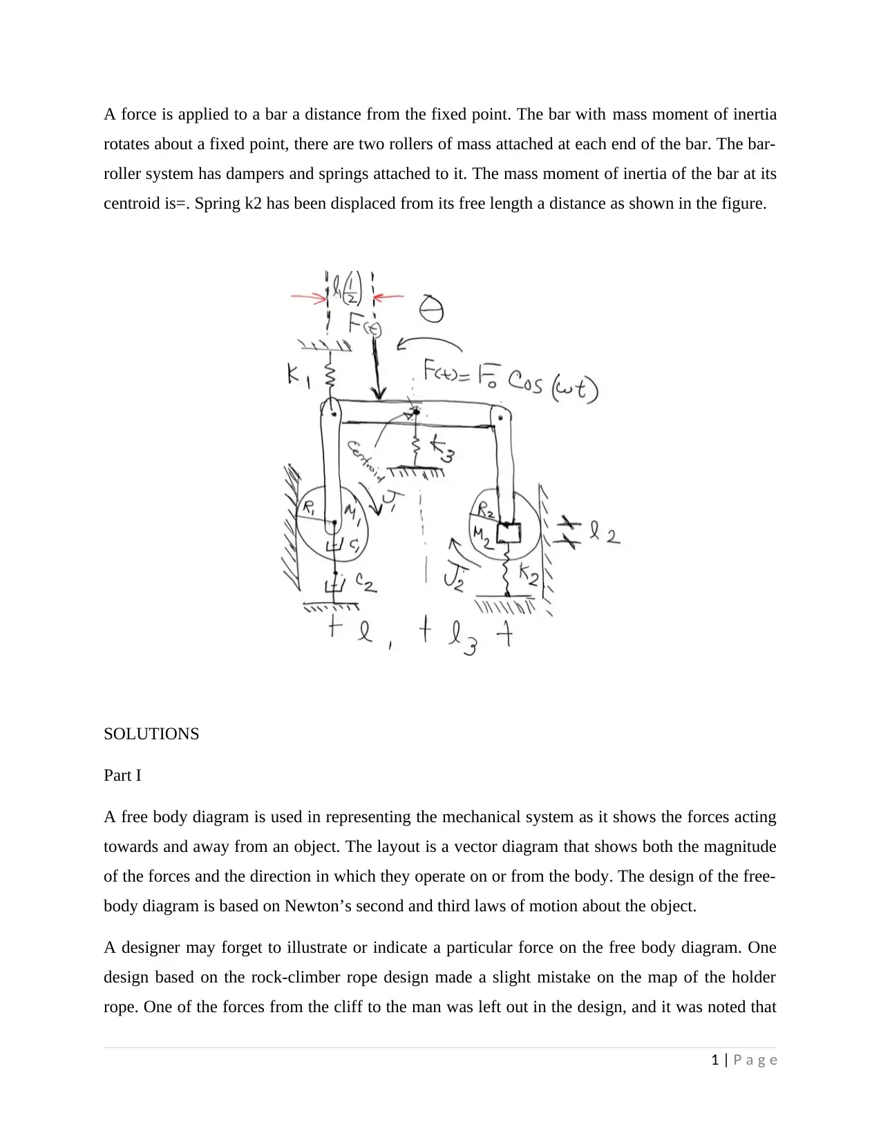
A force is applied to a bar a distance from the fixed point. The bar with mass moment of inertia
rotates about a fixed point, there are two rollers of mass attached at each end of the bar. The bar-
roller system has dampers and springs attached to it. The mass moment of inertia of the bar at its
centroid is=. Spring k2 has been displaced from its free length a distance as shown in the figure.
SOLUTIONS
Part I
A free body diagram is used in representing the mechanical system as it shows the forces acting
towards and away from an object. The layout is a vector diagram that shows both the magnitude
of the forces and the direction in which they operate on or from the body. The design of the free-
body diagram is based on Newton’s second and third laws of motion about the object.
A designer may forget to illustrate or indicate a particular force on the free body diagram. One
design based on the rock-climber rope design made a slight mistake on the map of the holder
rope. One of the forces from the cliff to the man was left out in the design, and it was noted that
1 | P a g e
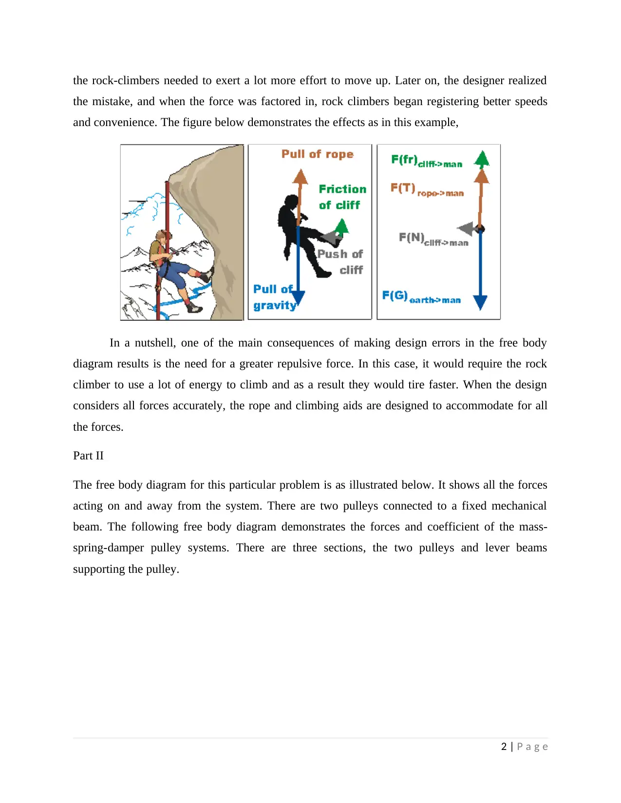
the rock-climbers needed to exert a lot more effort to move up. Later on, the designer realized
the mistake, and when the force was factored in, rock climbers began registering better speeds
and convenience. The figure below demonstrates the effects as in this example,
In a nutshell, one of the main consequences of making design errors in the free body
diagram results is the need for a greater repulsive force. In this case, it would require the rock
climber to use a lot of energy to climb and as a result they would tire faster. When the design
considers all forces accurately, the rope and climbing aids are designed to accommodate for all
the forces.
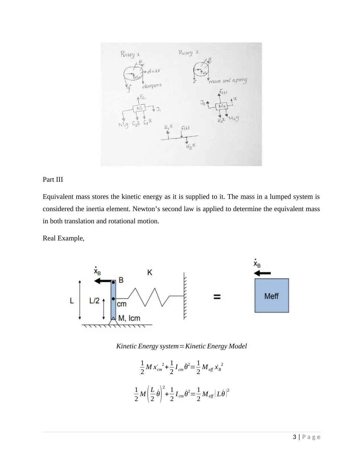
Part II
The free body diagram for this particular problem is as illustrated below. It shows all the forces
acting on and away from the system. There are two pulleys connected to a fixed mechanical
beam. The following free body diagram demonstrates the forces and coefficient of the mass-
spring-damper pulley systems. There are three sections, the two pulleys and lever beams
supporting the pulley.
2 | P a g e
the mistake, and when the force was factored in, rock climbers began registering better speeds
and convenience. The figure below demonstrates the effects as in this example,
In a nutshell, one of the main consequences of making design errors in the free body
diagram results is the need for a greater repulsive force. In this case, it would require the rock
climber to use a lot of energy to climb and as a result they would tire faster. When the design
considers all forces accurately, the rope and climbing aids are designed to accommodate for all
the forces.
Part II
The free body diagram for this particular problem is as illustrated below. It shows all the forces
acting on and away from the system. There are two pulleys connected to a fixed mechanical
beam. The following free body diagram demonstrates the forces and coefficient of the mass-
spring-damper pulley systems. There are three sections, the two pulleys and lever beams
supporting the pulley.
2 | P a g e
⊘ This is a preview!⊘
Do you want full access?
Subscribe today to unlock all pages.
Trusted by 1+ million students worldwide
Part III
Equivalent mass stores the kinetic energy as it is supplied to it. The mass in a lumped system is
considered the inertia element. Newton’s second law is applied to determine the equivalent mass
in both translation and rotational motion.
Real Example,
Kinetic Energy system=Kinetic Energy Model
1
2 M ˙xcm
2 + 1
2 Icm ˙θ2= 1
2 Meff ˙xB
2
1
2 M ( L
2 ˙θ ) 2
+ 1
2 I cm ˙θ2= 1
2 M eff ( L ˙θ ) 2
3 | P a g e
Paraphrase This Document
Need a fresh take? Get an instant paraphrase of this document with our AI Paraphraser
M
4 + I cm
L2 =Meff
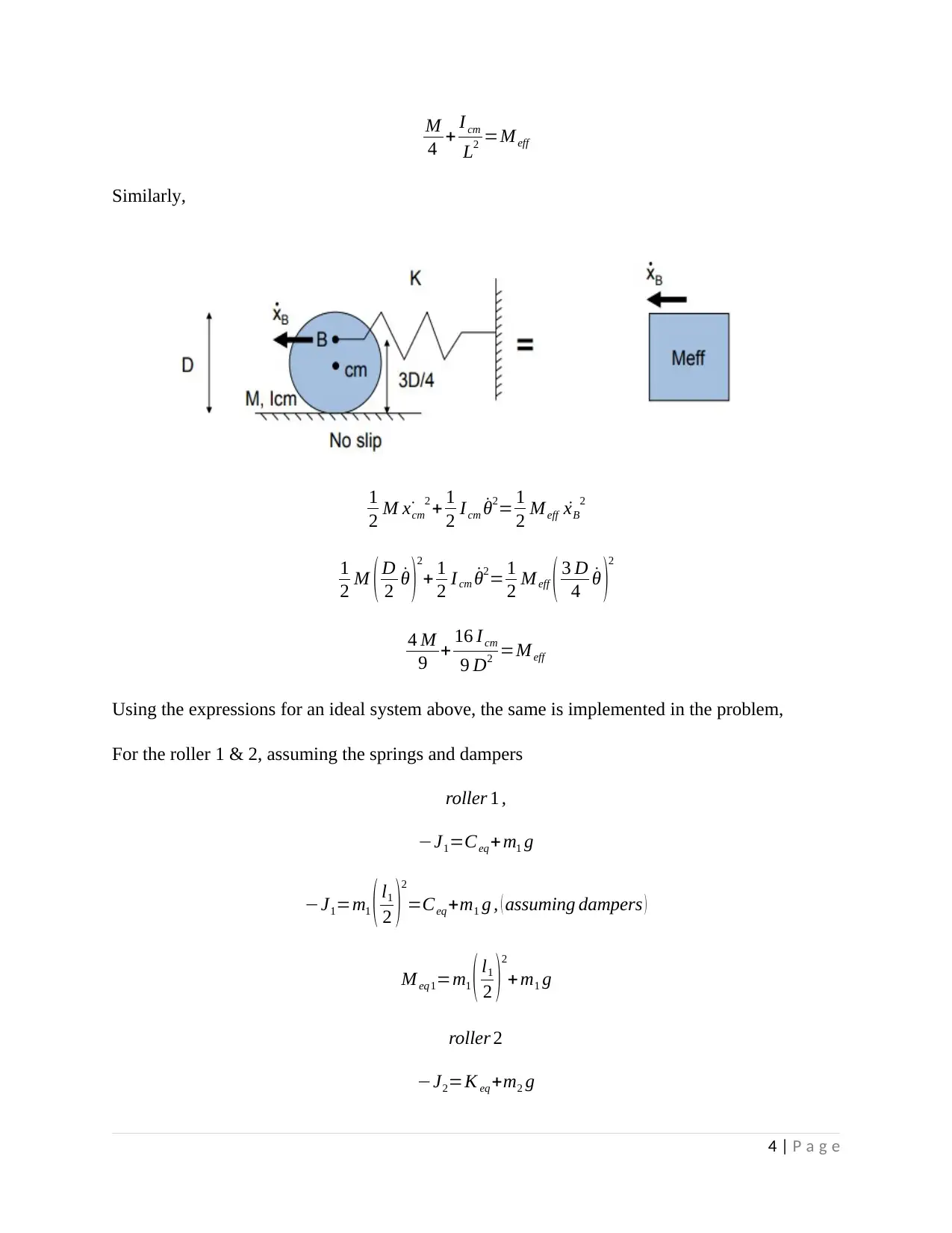
Similarly,
1
2 M ˙xcm
2 + 1
2 Icm ˙θ2= 1
2 Meff ˙xB
2
1
2 M ( D
2 ˙θ )2
+ 1
2 I cm ˙θ2= 1
2 Meff ( 3 D
4 ˙θ )2
4 M
9 + 16 I cm
9 D2 =M eff
Using the expressions for an ideal system above, the same is implemented in the problem,
For the roller 1 & 2, assuming the springs and dampers
roller 1 ,
−J1=Ceq+m1 g
−J1=m1 ( l1
2 )2
=Ceq+m1 g , ( assuming dampers )
M eq1=m1 ( l1
2 )
2
+ m1 g
roller 2
−J2=K eq +m2 g
4 | P a g e
4 + I cm
L2 =Meff
Similarly,
1
2 M ˙xcm
2 + 1
2 Icm ˙θ2= 1
2 Meff ˙xB
2
1
2 M ( D
2 ˙θ )2
+ 1
2 I cm ˙θ2= 1
2 Meff ( 3 D
4 ˙θ )2
4 M
9 + 16 I cm
9 D2 =M eff
Using the expressions for an ideal system above, the same is implemented in the problem,
For the roller 1 & 2, assuming the springs and dampers
roller 1 ,
−J1=Ceq+m1 g
−J1=m1 ( l1
2 )2
=Ceq+m1 g , ( assuming dampers )
M eq1=m1 ( l1
2 )
2
+ m1 g
roller 2
−J2=K eq +m2 g
4 | P a g e
J2=m2 ( l3
2 )
2
=X eq+m2 g , ( assuming springs )
M eq2=m2 ( l3
2 )
2
+m2 g
The mass moment of inertia at the bar at its centroid is given. Hence, for the support bars,
Jb =mb l2
2
So, the bar and the rollers act in opposite directions, therefore, the equivalent mass is given as,
meq=mb l2
2−m2 ( l3
2 )
2
−m2 g−m1 ( l1
2 )
2
−m1 g
meq=mb l2
2−m2 ( ( l3
2 )2
−g )−m1 (( l1
2 )2
+ g )
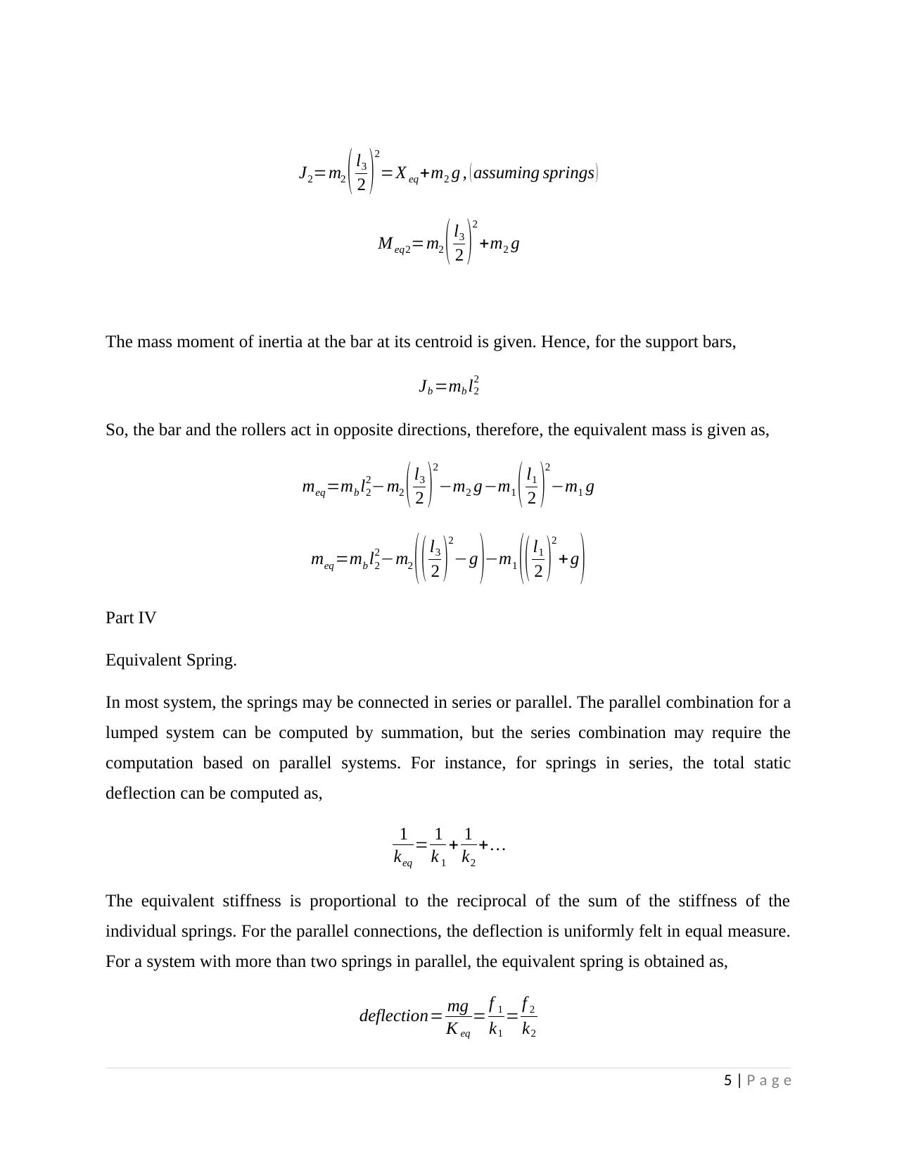
Part IV
Equivalent Spring.
In most system, the springs may be connected in series or parallel. The parallel combination for a
lumped system can be computed by summation, but the series combination may require the
computation based on parallel systems. For instance, for springs in series, the total static
deflection can be computed as,
1
keq
= 1
k 1
+ 1
k2
+…
The equivalent stiffness is proportional to the reciprocal of the sum of the stiffness of the
individual springs. For the parallel connections, the deflection is uniformly felt in equal measure.
For a system with more than two springs in parallel, the equivalent spring is obtained as,
deflection= mg
K eq
= f 1
k1
= f 2
k2
5 | P a g e
2 )
2
=X eq+m2 g , ( assuming springs )
M eq2=m2 ( l3
2 )
2
+m2 g
The mass moment of inertia at the bar at its centroid is given. Hence, for the support bars,
Jb =mb l2
2
So, the bar and the rollers act in opposite directions, therefore, the equivalent mass is given as,
meq=mb l2
2−m2 ( l3
2 )
2
−m2 g−m1 ( l1
2 )
2
−m1 g
meq=mb l2
2−m2 ( ( l3
2 )2
−g )−m1 (( l1
2 )2
+ g )
Part IV
Equivalent Spring.
In most system, the springs may be connected in series or parallel. The parallel combination for a
lumped system can be computed by summation, but the series combination may require the
computation based on parallel systems. For instance, for springs in series, the total static
deflection can be computed as,
1
keq
= 1
k 1
+ 1
k2
+…
The equivalent stiffness is proportional to the reciprocal of the sum of the stiffness of the
individual springs. For the parallel connections, the deflection is uniformly felt in equal measure.
For a system with more than two springs in parallel, the equivalent spring is obtained as,
deflection= mg
K eq
= f 1
k1
= f 2
k2
5 | P a g e
⊘ This is a preview!⊘
Do you want full access?
Subscribe today to unlock all pages.
Trusted by 1+ million students worldwide
mg=f 1 +f 2
k eq ( deflection→ ∆ ) =k 1 ∆+ k2 ∆
k eq=k1+ k2
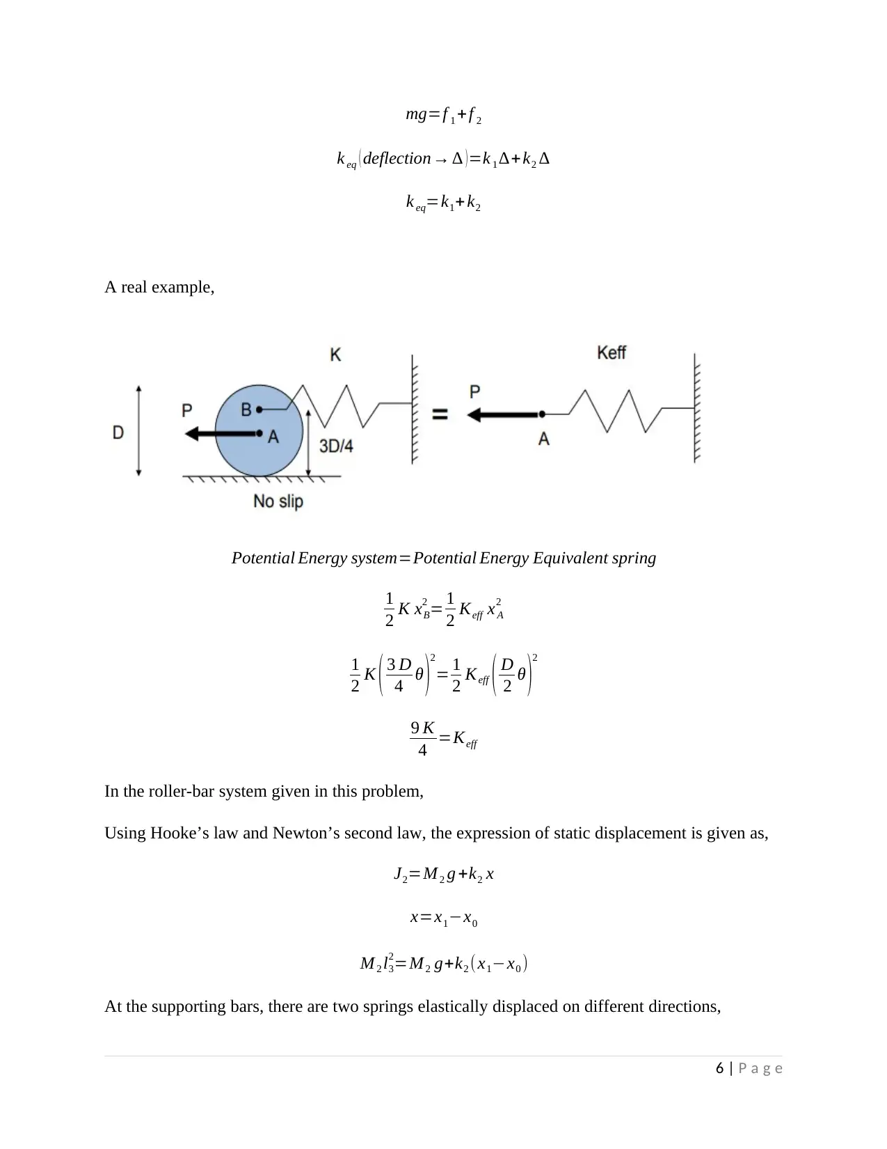
A real example,
Potential Energy system=Potential Energy Equivalent spring
1
2 K xB
2 = 1
2 Keff x A
2
1
2 K ( 3 D
4 θ )
2
= 1
2 Keff ( D
2 θ )
2
9 K
4 =Keff
In the roller-bar system given in this problem,
Using Hooke’s law and Newton’s second law, the expression of static displacement is given as,
J2=M 2 g +k2 x
x=x1−x0
M 2 l3
2=M 2 g+k2 (x1−x0 )
At the supporting bars, there are two springs elastically displaced on different directions,
6 | P a g e
k eq ( deflection→ ∆ ) =k 1 ∆+ k2 ∆
k eq=k1+ k2
A real example,
Potential Energy system=Potential Energy Equivalent spring
1
2 K xB
2 = 1
2 Keff x A
2
1
2 K ( 3 D
4 θ )
2
= 1
2 Keff ( D
2 θ )
2
9 K
4 =Keff
In the roller-bar system given in this problem,
Using Hooke’s law and Newton’s second law, the expression of static displacement is given as,
J2=M 2 g +k2 x
x=x1−x0
M 2 l3
2=M 2 g+k2 (x1−x0 )
At the supporting bars, there are two springs elastically displaced on different directions,
6 | P a g e
Paraphrase This Document
Need a fresh take? Get an instant paraphrase of this document with our AI Paraphraser
F ( t ) ( l1
2 )+ k3 ( x1 −x0 ) ( l3
2 ) =k1 ( x1−x0 ) ( l1
2 )
M 2 l3
2=M 2 g+k2 (x1−x0 )
The equivalent spring is given as an addition of the spring coefficients
Keq=k3 ( l2
2 ) +k 2 ( l3
2 ) −k1 ( l1
2 )
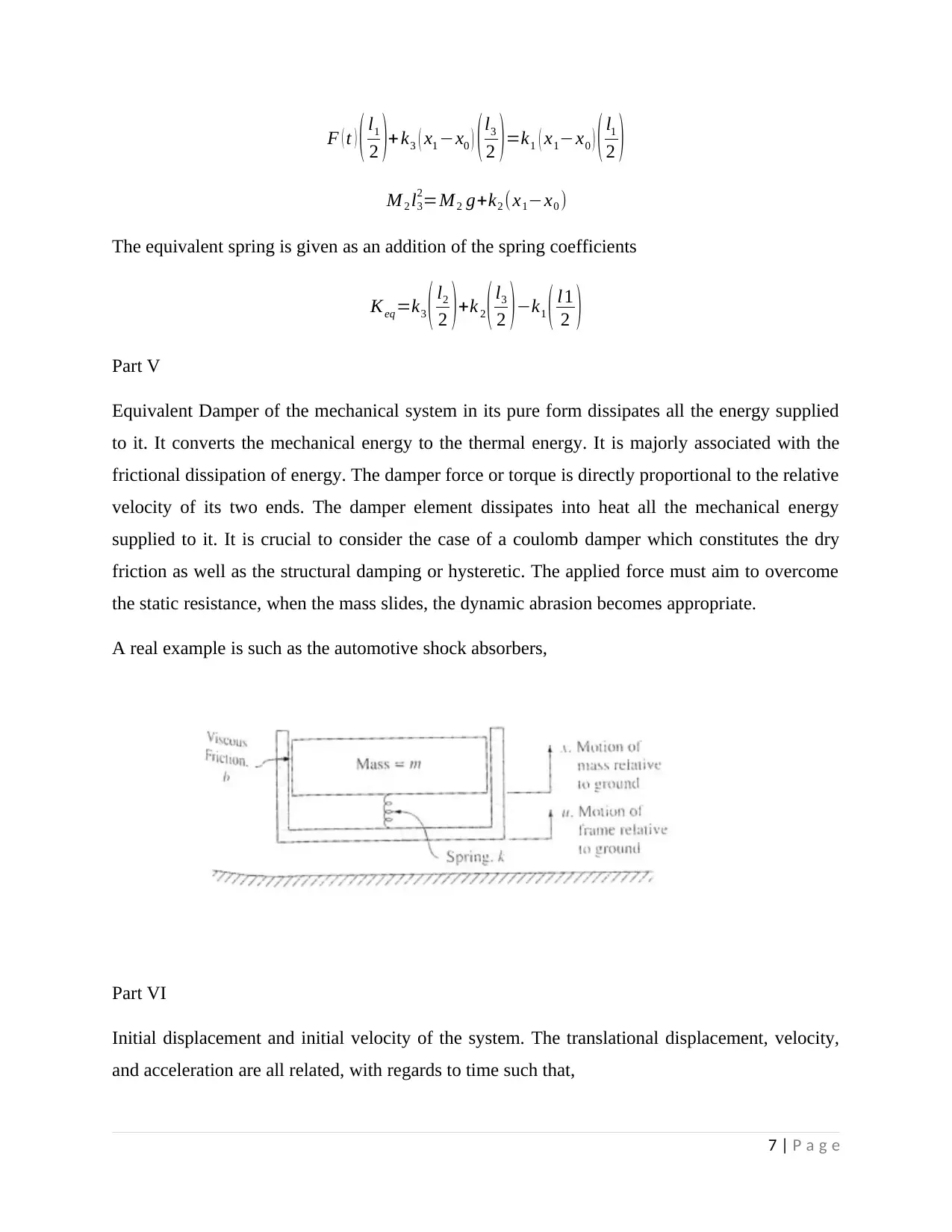
Part V
Equivalent Damper of the mechanical system in its pure form dissipates all the energy supplied
to it. It converts the mechanical energy to the thermal energy. It is majorly associated with the
frictional dissipation of energy. The damper force or torque is directly proportional to the relative
velocity of its two ends. The damper element dissipates into heat all the mechanical energy
supplied to it. It is crucial to consider the case of a coulomb damper which constitutes the dry
friction as well as the structural damping or hysteretic. The applied force must aim to overcome
the static resistance, when the mass slides, the dynamic abrasion becomes appropriate.
A real example is such as the automotive shock absorbers,
Part VI
Initial displacement and initial velocity of the system. The translational displacement, velocity,
and acceleration are all related, with regards to time such that,
7 | P a g e
2 )+ k3 ( x1 −x0 ) ( l3
2 ) =k1 ( x1−x0 ) ( l1
2 )
M 2 l3
2=M 2 g+k2 (x1−x0 )
The equivalent spring is given as an addition of the spring coefficients
Keq=k3 ( l2
2 ) +k 2 ( l3
2 ) −k1 ( l1
2 )
Part V
Equivalent Damper of the mechanical system in its pure form dissipates all the energy supplied
to it. It converts the mechanical energy to the thermal energy. It is majorly associated with the
frictional dissipation of energy. The damper force or torque is directly proportional to the relative
velocity of its two ends. The damper element dissipates into heat all the mechanical energy
supplied to it. It is crucial to consider the case of a coulomb damper which constitutes the dry
friction as well as the structural damping or hysteretic. The applied force must aim to overcome
the static resistance, when the mass slides, the dynamic abrasion becomes appropriate.
A real example is such as the automotive shock absorbers,
Part VI
Initial displacement and initial velocity of the system. The translational displacement, velocity,
and acceleration are all related, with regards to time such that,
7 | P a g e
a= dv
dt = d2 x
d t2
a= ˙v = ¨x
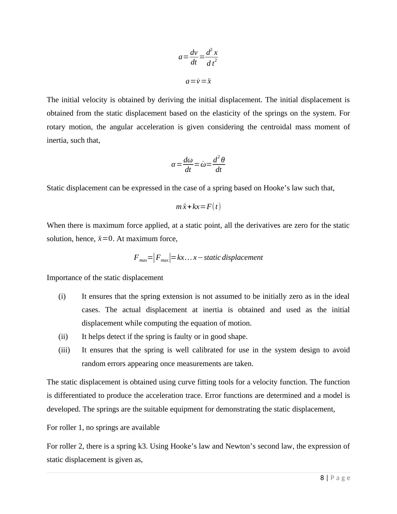
The initial velocity is obtained by deriving the initial displacement. The initial displacement is
obtained from the static displacement based on the elasticity of the springs on the system. For
rotary motion, the angular acceleration is given considering the centroidal mass moment of
inertia, such that,
α = dω
dt = ˙ω= d2 θ
dt
Static displacement can be expressed in the case of a spring based on Hooke’s law such that,
m ¨x +kx=F(t)
When there is maximum force applied, at a static point, all the derivatives are zero for the static
solution, hence, ¨x=0. At maximum force,
Fmax=|Fmax |=kx … x−static displacement
Importance of the static displacement
(i) It ensures that the spring extension is not assumed to be initially zero as in the ideal
cases. The actual displacement at inertia is obtained and used as the initial
displacement while computing the equation of motion.
(ii) It helps detect if the spring is faulty or in good shape.
(iii) It ensures that the spring is well calibrated for use in the system design to avoid
random errors appearing once measurements are taken.
The static displacement is obtained using curve fitting tools for a velocity function. The function
is differentiated to produce the acceleration trace. Error functions are determined and a model is
developed. The springs are the suitable equipment for demonstrating the static displacement,
For roller 1, no springs are available
For roller 2, there is a spring k3. Using Hooke’s law and Newton’s second law, the expression of
static displacement is given as,
8 | P a g e
dt = d2 x
d t2
a= ˙v = ¨x
The initial velocity is obtained by deriving the initial displacement. The initial displacement is
obtained from the static displacement based on the elasticity of the springs on the system. For
rotary motion, the angular acceleration is given considering the centroidal mass moment of
inertia, such that,
α = dω
dt = ˙ω= d2 θ
dt
Static displacement can be expressed in the case of a spring based on Hooke’s law such that,
m ¨x +kx=F(t)
When there is maximum force applied, at a static point, all the derivatives are zero for the static
solution, hence, ¨x=0. At maximum force,
Fmax=|Fmax |=kx … x−static displacement
Importance of the static displacement
(i) It ensures that the spring extension is not assumed to be initially zero as in the ideal
cases. The actual displacement at inertia is obtained and used as the initial
displacement while computing the equation of motion.
(ii) It helps detect if the spring is faulty or in good shape.
(iii) It ensures that the spring is well calibrated for use in the system design to avoid
random errors appearing once measurements are taken.
The static displacement is obtained using curve fitting tools for a velocity function. The function
is differentiated to produce the acceleration trace. Error functions are determined and a model is
developed. The springs are the suitable equipment for demonstrating the static displacement,
For roller 1, no springs are available
For roller 2, there is a spring k3. Using Hooke’s law and Newton’s second law, the expression of
static displacement is given as,
8 | P a g e
⊘ This is a preview!⊘
Do you want full access?
Subscribe today to unlock all pages.
Trusted by 1+ million students worldwide
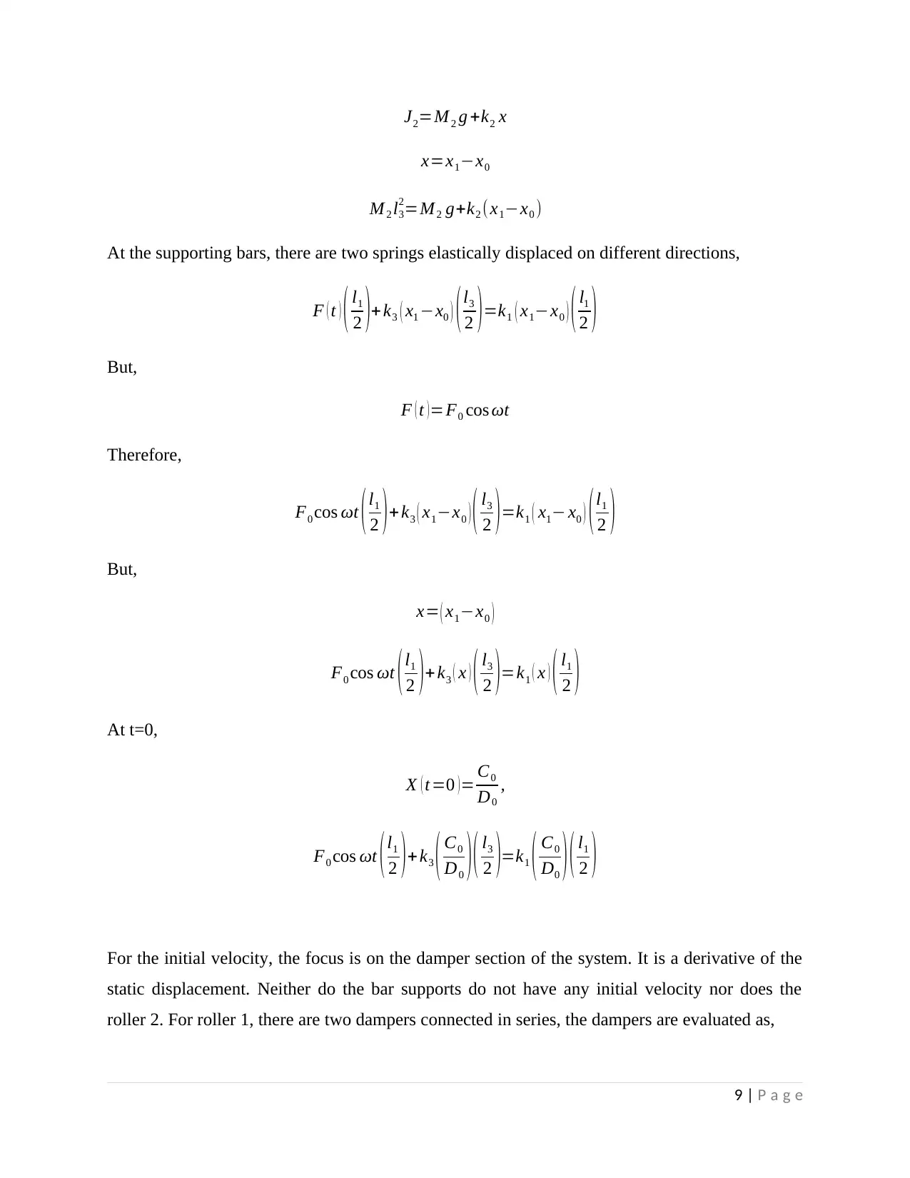
J2=M 2 g +k2 x
x=x1−x0
M 2 l3
2=M 2 g+k2 (x1−x0 )
At the supporting bars, there are two springs elastically displaced on different directions,
F ( t ) ( l1
2 )+ k3 ( x1 −x0 ) ( l3
2 ) =k1 ( x1−x0 ) ( l1
2 )
But,
F ( t ) =F0 cos ωt
Therefore,
F0 cos ωt ( l1
2 ) + k3 ( x1−x0 ) ( l3
2 ) =k1 ( x1− x0 ) ( l1
2 )
But,
x= ( x1−x0 )
F0 cos ωt (l1
2 )+ k3 ( x ) ( l3
2 )=k1 ( x ) ( l1
2 )
At t=0,
X ( t=0 ) = C0
D0
,
F0 cos ωt (l1
2 )+ k3 ( C0
D0 ) ( l3
2 )=k1 ( C0
D0 ) ( l1
2 )
For the initial velocity, the focus is on the damper section of the system. It is a derivative of the
static displacement. Neither do the bar supports do not have any initial velocity nor does the
roller 2. For roller 1, there are two dampers connected in series, the dampers are evaluated as,
9 | P a g e
Paraphrase This Document
Need a fresh take? Get an instant paraphrase of this document with our AI Paraphraser
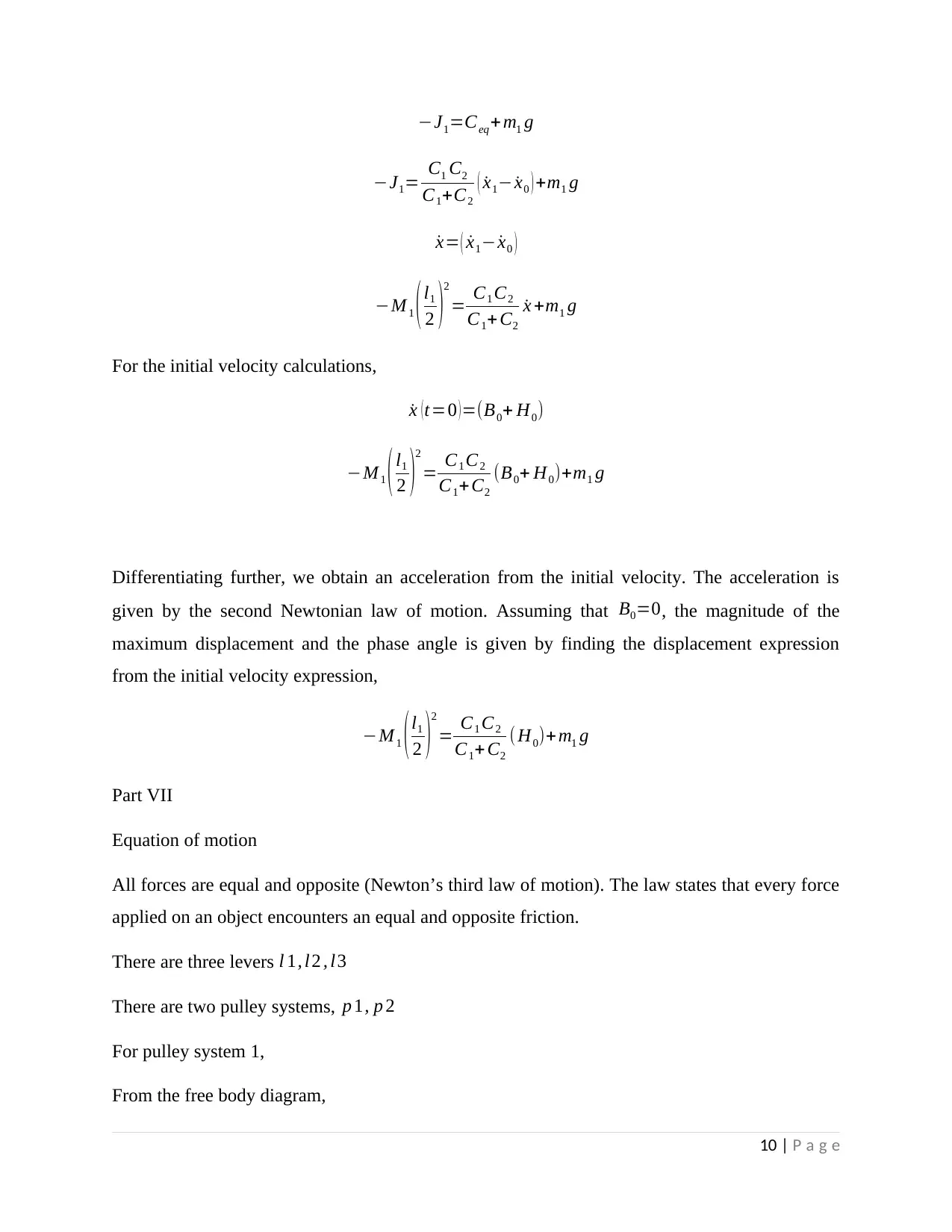
−J1=Ceq+m1 g
−J1= C1 C2
C1+C2
( ˙x1− ˙x0 ) +m1 g
˙x= ( ˙x1− ˙x0 )
−M 1 ( l1
2 )
2
= C1 C2
C1+ C2
˙x +m1 g
For the initial velocity calculations,
˙x ( t=0 ) =(B0+ H0)
−M 1 ( l1
2 )
2
= C1 C2
C1+ C2
(B0+ H0)+m1 g
Differentiating further, we obtain an acceleration from the initial velocity. The acceleration is
given by the second Newtonian law of motion. Assuming that B0=0, the magnitude of the
maximum displacement and the phase angle is given by finding the displacement expression
from the initial velocity expression,
−M 1 ( l1
2 )
2
= C1 C2
C1+ C2
( H0)+ m1 g
Part VII
Equation of motion
All forces are equal and opposite (Newton’s third law of motion). The law states that every force
applied on an object encounters an equal and opposite friction.
There are three levers l 1, l2 , l3
There are two pulley systems, p 1, p 2
For pulley system 1,
From the free body diagram,
10 | P a g e
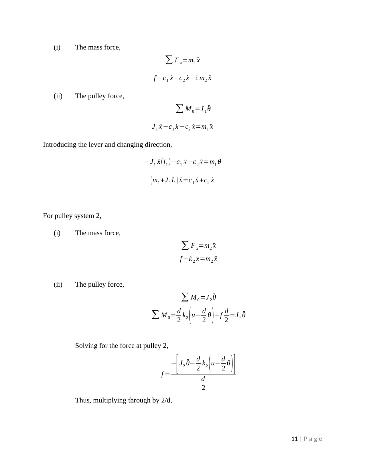
(i) The mass force,
∑ F x=m1 ¨x
f −c1 ˙x−c2 ˙x−¿ m2 ¨x
(ii) The pulley force,
∑ M 0 =J 1 ¨θ
J1 ¨x −c1 ˙x−c2 ˙x=m1 ¨x
Introducing the lever and changing direction,
−J1 ¨x(l1 )−c1 ˙x−c2 ˙x=m1 ¨θ
( m1 +J 1 l1 ) ¨x=c1 ˙x +c2 ˙x
For pulley system 2,
(i) The mass force,
∑ F x=m2 ¨x
f −k 2 x=m2 ¨x
(ii) The pulley force,
∑ M0 =J 2 ¨θ
∑ M 0 = d
2 k2 ( u− d
2 θ )−f d
2 =J 2 ¨θ
Solving for the force at pulley 2,
f =
−
[ J2 ¨θ− d
2 k2 ( u− d
2 θ ) ]
d
2
Thus, multiplying through by 2/d,
11 | P a g e
⊘ This is a preview!⊘
Do you want full access?
Subscribe today to unlock all pages.
Trusted by 1+ million students worldwide
1 out of 18


Your All-in-One AI-Powered Toolkit for Academic Success.
+13062052269
info@desklib.com
Available 24*7 on WhatsApp / Email
![[object Object]](/_next/static/media/star-bottom.7253800d.svg)
Unlock your academic potential
Copyright © 2020–2026 A2Z Services. All Rights Reserved. Developed and managed by ZUCOL.